GEOTEK ENGINEERING & TESTING SERVICES, INC. 909 East 50 th Street North Sioux Falls, South Dakota Phone Fax
|
|
|
- Kelley Dalton
- 6 years ago
- Views:
Transcription
1 GEOTEK ENGINEERING & TESTING SERVICES, INC. 909 East 50 th Street North Sioux Falls, South Dakota Phone Fax October 28, 2016 City of Vermillion 25 Center Street Attn: Shane Griese, Utilities Manager Subj: Geotechnical Exploration Proposed Lift Station Replacement & Sanitary Sewer Improvements City of Vermillion This correspondence presents our written report of the geotechnical exploration program for the referenced project. Our work was performed in accordance with your authorization. We are transmitting an electronic copy of our report for your use. An additional copy is also being sent as noted below. We thank you for the opportunity of providing our services on this project and look forward to continued participation during the design and construction phases. If you have any questions regarding this report, please contact our office at (605) Respectfully Submitted, Jared Haskins Jared Haskins, PE Geotechnical Manager Cc: Banner Associates, Inc., Attn: Tanya Miller, PE
2 Proposed Lift Station Replacement & Sanitary Sewer Improvements Page 2 of 16 TABLE OF CONTENTS INTRODUCTION... 4 PROJECT INFORMATION... 4 SCOPE OF SERVICES... 4 SITE & SUBSURFACE CONDITIONS... 5 SITE LOCATION & DESCRIPTION... 5 GROUND SURFACE ELEVATIONS & TEST BORING LOCATIONS... 5 EXISTING PAVEMENT CONDITIONS... 5 SUBSURFACE CONDITIONS... 6 WATER LEVELS... 6 ENGINEERING REVIEW & RECOMMENDATIONS... 7 PROJECT DESIGN DATA... 7 LIFT STATION TEST BORING Dewatering & Stable Condition... 7 Soil Parameters Temporary Shoring Design... 8 UTILITY EXCAVATIONS... 8 Subgrade Soils... 8 Dewatering... 8 Trench Backfill... 9 OSHA SOIL TYPES... 9 PAVEMENT Discussion Earthwork Activities Aggregate Thickness & Geotextile Fabric Pavement Thickness CONSTRUCTION CONSIDERATIONS GROUNDWATER & SURFACE WATER DISTURBANCE OF SOILS COLD WEATHER PRECAUTIONS EXCAVATION SIDESLOPES OBSERVATIONS & TESTING Excavation Testing SUBSURFACE EXPLORATION PROCEDURES TEST BORINGS SOIL CLASSIFICATION WATER LEVEL MEASUREMENTS LABORATORY TESTS LIMITATIONS STANDARD OF CARE... 16
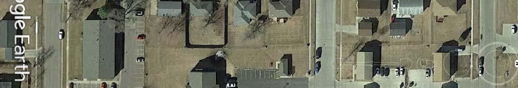
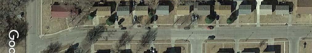
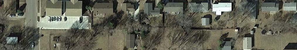
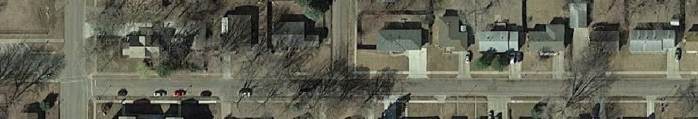
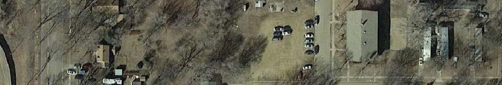
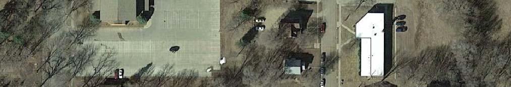
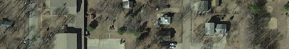
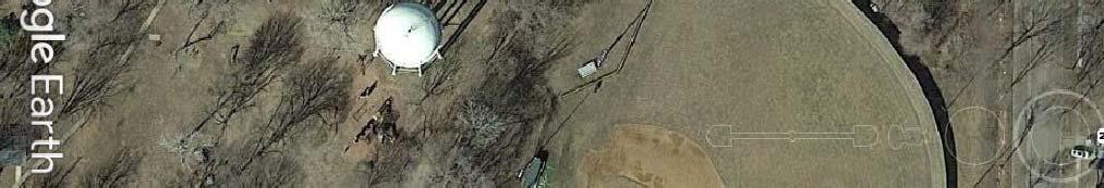
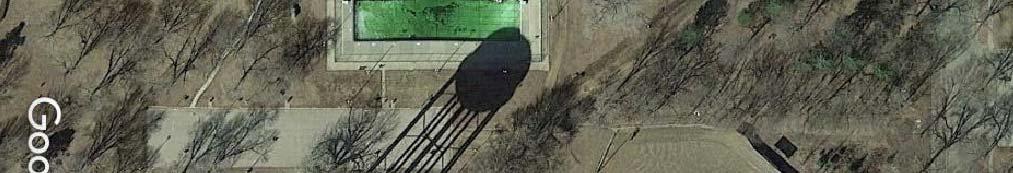
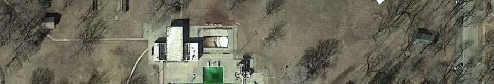
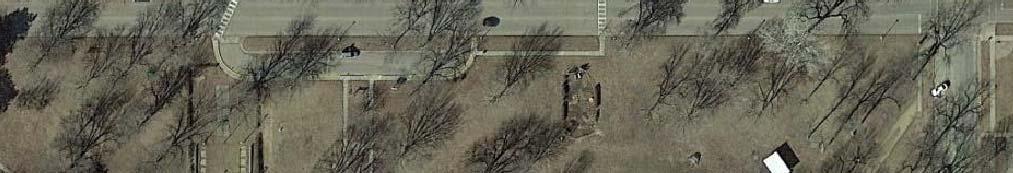
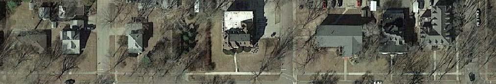
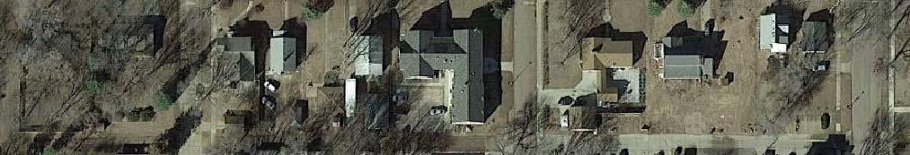
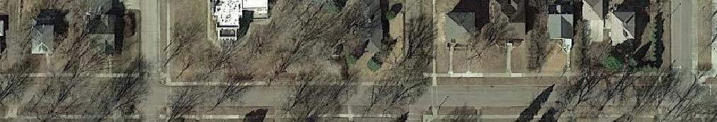
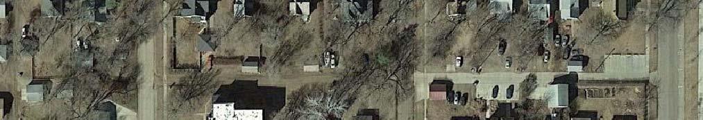
3 Proposed Lift Station Replacement & Sanitary Sewer Improvements Page 3 of 16 APPENDIX A FIGURE 1 TEST BORING LOCATION MAP (TEST BORINGS 1 & 2) FIGURE 2 TEST BORING LOCATION MAP (TEST BORINGS 3 & 4) FIGURE 3 SOIL PARAMETERS TEST BORING 1 BORING LOGS SOIL CLASSIFICATION SHEET SYMBOLS & DESCRIPTIVE TERMINOLOGY PROCTOR DATA SHEETS
4 Proposed Lift Station Replacement & Sanitary Sewer Improvements Page 4 of 16 GEOTECHNICAL EXPLORATION PROPOSED LIFT STATION REPLACEMENT & SANITARY SEWER IMPROVEMENTS CITY OF VERMILLION VERMILLION, SOUTH DAKOTA GEOTEK #16-C29 INTRODUCTION Project Information This report presents the results of the recent geotechnical exploration program for the proposed lift station replacement and sanitary sewer improvements for the City of Vermillion in. Scope of Services Our work was performed in accordance with the authorization of Shane Griese with the City of Vermillion. The scope of work as presented in this report is limited to the following: 1. To perform four (4) standard penetration test () borings to gather data on the subsurface conditions at the project site. 2. To perform laboratory tests that include moisture content, dry density, sieve analysis (#200 sieve wash), Atterberg limits (liquid and plastic limits), unconfined compressive strength and standard Proctor. 3. To prepare an engineering report that includes the results of the field and laboratory tests as well as our geotechnical engineering opinions and recommendations regarding the following: Existing pavement section; Lift station; Temporary shoring; Potential groundwater control; Utility backfill; Subgrade strength and potential corrective measures; Aggregate section thickness; OSHA soil classes for excavation; Comments regarding factors that may impact the constructability and final performance of the project; Quality control observations and testing.
5 Proposed Lift Station Replacement & Sanitary Sewer Improvements Page 5 of 16 The scope of our work was intended for geotechnical purposes only. This scope of work did not include determining the presence or extent of environmental contamination at the site or to characterize the site relative to wetlands status. SITE & SUBSURFACE CONDITIONS Site Location & Description The existing lift station is located approximately 300 feet south of the intersection of Lincoln Street and Prentis Avenue (east side of Prentis Avenue). The current site features near the location of the existing lift station consist of the following: two (2) residences, a street (Prentis Avenue), grass areas, a sidewalk, a driveway, a tree and a light pole. The sanitary sewer improvements will be performed on Prentis Avenue from the lift station to Clark Street, on Clark Street from Prentis Avenue to Plum Street and on Plum Street from Clark Street to National Street. Ground Surface Elevations & Test Boring Locations We did not determine the ground surface elevations at the test boring locations. Two (2) test boring location maps are attached showing the relative location of the test borings. Existing Pavement Conditions Table 1 summarizes the thickness of the existing pavement and gravel base encountered at the respective test boring locations. Table 1. Thickness of the Existing Pavement & Gravel Base Test Boring Street Asphalt Thickness, in Concrete Pavement, in Gravel Base Thickness, in 1* Prentis Avenue Clark Street Plum Street Plum Street *Test boring 1 was performed for the lift station within the street.
6 Proposed Lift Station Replacement & Sanitary Sewer Improvements Page 6 of 16 Subsurface Conditions Four (4) test borings were performed on October 11, Of the four (4) test borings, one (1) test boring (test boring 1) was performed for the lift station and three (3) test borings (test borings 2, 3 and 4) were performed for the sanitary sewer improvements. The subsurface conditions encountered at the test boring locations are illustrated by means of the boring logs included in Appendix A. At test boring 1, existing fill materials extended to a depth of 4 ½ feet. Fine alluvium soils and mixed alluvium soils were encountered beneath the existing fill materials. At a depth of 12 feet, glacial till soils were encountered and extended to the termination depth of the test boring. At test borings 2, 3 and 4, existing fill materials, fine alluvium soils and glacial till soils were encountered beneath the existing pavement section. The glacial till soils were not encountered at test boring 2. The existing fill materials consisted of lean clay soils, clayey sand soils and silty sand soils. The fine alluvium soils consisted of lean clay soils. The mixed alluvium soils consisted of sandy lean clay soils. The glacial till soils consisted of lean clay with sand soils and sandy lean clay soils. The consistency or relative density of the soils is indicated by the standard penetration resistance ( N ) values as shown on the boring logs. A description of the soil consistency or relative density based on the N values can be found on the attached Soil Boring Symbols and Descriptive Terminology data sheet. We wish to point out that the subsurface conditions at other times and locations at the site may differ from those found at our test boring locations. If different conditions are encountered during construction, then it is important that you contact us so that our recommendations can be reviewed. Water Levels Measurements to record the groundwater levels were made at the test boring locations. The time and level of the groundwater readings are recorded on the boring logs. Groundwater was
7 Proposed Lift Station Replacement & Sanitary Sewer Improvements Page 7 of 16 measured at depths varying from 8 feet to 12 feet at test borings 1, 2 and 3. Groundwater did not enter the borehole at test boring 4 at the time of our measurements. The water levels indicated on the boring logs may or may not be an accurate indication of the depth or lack of subsurface groundwater. The limited length of observation restricts the accuracy of the measurements. Long term groundwater monitoring was not included in our scope of work. ENGINEERING REVIEW & RECOMMENDATIONS Project Design Data We understand that the project will consist of replacing an existing lift station with a new lift station. The new lift station will be a steel can and the wet well will be precast concrete. The new lift station will have a depth of approximately 20 feet. We understand that temporary shoring will be needed for the installation of the lift station. The project will also consist of sanitary sewer improvements. The information/assumptions detailed in the project design data section of the report are important factors in our review and recommendations. If there are any corrections or additions to the information detailed in this section, it is important that you contact us so that we can review our recommendations with regards to the revised plans. Lift Station Test Boring 1 Dewatering & Stable Condition The groundwater measurement at test boring 1 indicates that the groundwater level is above the design elevation of the lift station. Therefore, dewatering will likely be needed during the installation of the lift station. It will likely be possible to remove and control water entering the excavation using normal sump pumping techniques due to the low permeable characteristics of the predominant clayey soils encountered at test boring 1. However, if lenses or layers of waterbearing sand soils are encountered, then more extensive dewatering techniques would likely be needed. We would like to point out that lenses of sand were encountered within the fine alluvium soils and mixed alluvium soils from 4 ½ feet to 12 feet. In an effort to provide a stable
8 Proposed Lift Station Replacement & Sanitary Sewer Improvements Page 8 of 16 condition for the installation of the lift station, we recommend placing a minimum of 12 inches of drainage rock at the bottom of the excavation. The drainage rock should be crushed, washed and have 100 percent by weight passing the 1-inch sieve and no more than 5 percent by weight passing the #4 sieve. The drainage rock will also help facilitate drainage at the bottom of the excavation. Soil Parameters Temporary Shoring Design As previously stated, we understand that temporary shoring will be needed for the installation of the lift station. We have provided soil parameters for the design of the temporary shoring (Figure 3 attached at the conclusion of the report). We would like to point out that the parameters shown in Figure 3 are based on a groundwater level of approximately 5 feet. This does not mean that groundwater was encountered at a depth of 5 feet; it is to account for future fluctuations in the groundwater level. We can also provide additional soil parameters if needed. Utility Excavations Subgrade Soils The subgrade soils anticipated at the invert depths for the sanitary sewer will likely consist of clay soils. Where soils having moderate moisture and density values are encountered at the bottom of the trench excavations, it is our opinion that the soils are considered suitable for support of the proposed sanitary sewer, provided they are adequately dewatered, and are not disturbed by construction traffic. Areas of wet or soft soils will likely be encountered at the bottom of the trench excavations. These areas will require subexcavation and trench stabilization methods and materials. Appropriate bedding materials should be used for the sanitary sewer. Dewatering Water may enter the trench excavations as a result of subsurface water, precipitation or surface run off. Dewatering procedures will likely be required in order to control and remove water during the excavation for the sanitary sewer. Where clay soils are encountered, it may be possible to remove and control water entering the excavations using normal sump pumping techniques. However, where waterbearing sand soils are encountered, extensive dewatering
9 Proposed Lift Station Replacement & Sanitary Sewer Improvements Page 9 of 16 techniques will likely be required due to the potentially large volumes of water. The contractor should provide appropriate dewatering methods and equipment. It should be noted that groundwater was measured at depths varying from 8 feet to 12 feet at test borings 1, 2 and 3. Any water that accumulates at the bottom of the excavations should be immediately removed and surface drainage away from the excavations should be provided during construction. Trench Backfill The results of the laboratory moisture content tests generally indicate that the on-site soils (existing fill materials, fine alluvium soils, mixed alluvium soils and glacial till soils) have high moisture content levels. In our opinion, it will be difficult to adjust the moisture content of the on-site soils to a level that will facilitate the specified compaction requirement. With that said, it is our opinion that the on-site soils should not be used as trench backfill. The on-site soils should be replaced by an off-site borrow material. The off-site borrow material should consist of either a granular or clay material. If a granular material is used, then it should consist of a pit-run or processed sand or gravel having a maximum particle size of 3 inches. The granular material can be placed in lifts of up to 1 foot in thickness. If a clay material is selected, then it should consist of a non-organic clay having a liquid limit less than 45. Scrutiny on the clay material s moisture content should be made prior to the acceptance and use. The clay fill should be placed in lifts of up to 6 inches in thickness. The moisture content of the trench backfill soils should be within plus or minus 2 percent of the optimum moisture content as determined by standard Proctor (ASTM:D698). The trench backfill should be compacted to a minimum of 95 percent of standard Proctor density (ASTM:D698). OSHA Soil Types It is our opinion that the existing fill materials, fine alluvium soils and mixed alluvium soils would be classified as Type C soils. The glacial till soils at test boring 3 would also be classified as a Type C soil. The glacial till soils from 12 feet to 19 ½ feet at test boring 1 would be classified as a Type B soil. The glacial till soils from 19 ½ feet to 46 feet at test boring 1 and at test boring 4 would be classified as Type A soils.
10 Proposed Lift Station Replacement & Sanitary Sewer Improvements Page 10 of 16 Pavement Discussion Even though we recommend the use of an off-site borrow material as trench backfill, a portion of the on-site soils will remain within the roadway. Again, the laboratory moisture content tests generally indicate that the on-site soils have high moisture content levels. It is our opinion that the on-site soils will provide low subgrade support for the pavement section. Therefore, it is our opinion that subgrade reinforcement will be needed below the pavement. The subgrade reinforcement should consist of coarse granular subbase overlying a geotextile fabric. Earthwork Activities Low-ground-pressure construction equipment or excavators with smooth-edged buckets should be used for the earthwork activities. The subgrade should not be exposed to heavy construction traffic from rubber tire vehicles. Aggregate Thickness & Geotextile Fabric We recommend that the aggregate section consist of a minimum of 4 inches of aggregate base course material overlying 10 inches of coarse granular subbase. A geotextile fabric should be installed beneath the coarse granular subbase. The thickness of the aggregate base course material is only 4 inches because coarse granular subbase and geotextile fabric is recommended. A thicker layer of aggregate base course material could be used but the thickness of the coarse granular subbase should not be reduced. We recommend that the aggregate base course material meet the requirements of Sections 260 and 882 of the SDDOT Standard Specifications. For the coarse granular subbase, it should consist of crushed quartzite, recycled concrete or a crushed pit-run material meeting the gradation specifications shown in Table 2.
11 Proposed Lift Station Replacement & Sanitary Sewer Improvements Page 11 of 16 Table 2. Granular Subbase Gradation Specifications Sieve Size Percent Passing 4-inch inch # # # The aggregate base course material and coarse granular subbase should be compacted to a minimum of 97 percent of standard Proctor (ASTM:D698); however, compaction testing of the coarse granular subbase may not be practical due to the large aggregate. Regarding the geotextile fabric, it should consist of Mirafi HP 370, Propex Geotex 3x3 HF, Huesker Comtrac P 45/45 or approved alternative. Pavement Thickness We assume that the pavement thickness will match that of the existing pavement. The asphalt pavement should meet the requirements of sections 320 and 321 for Class G. We recommend that the concrete pavement meet the requirements of Section 380 of the SDDOT Standard Specifications. CONSTRUCTION CONSIDERATIONS Groundwater & Surface Water Water may enter the excavations due to subsurface water, precipitation or surface run off. Any water that accumulates in the bottom of the excavations should be immediately removed and surface drainage away from the excavations should be provided during construction. Disturbance of Soils The soils encountered at the test boring locations are susceptible to disturbance and can experience strength loss caused by construction traffic and/or additional moisture. Precautions
12 Proposed Lift Station Replacement & Sanitary Sewer Improvements Page 12 of 16 will be required during earthwork activities in order to reduce the risk of soil disturbance. Lowground-pressure construction equipment or excavators with smooth-edged buckets should be used for the earthwork activities. Cold Weather Precautions If site preparation and construction is anticipated during cold weather, we recommend all subgrades, slabs and other improvements that may be affected by frost movements be insulated from frost penetration during freezing temperatures. If filling is performed during freezing temperatures, all frozen soils, snow and ice should be removed from the areas to be filled prior to placing the new fill. The new fill should not be allowed to freeze during transit, placement and compaction. Concrete and asphalt should not be placed on frozen subgrades. If subgrades freeze, we recommend that the frozen soils be removed and replaced, or completely thawed. The subgrade soils will likely require reworking and recompacting due to the loss of density caused by the freeze/thaw process. Excavation Sideslopes All excavations must comply with the requirements of OSHA 29 CFR, Part 1926, Subpart P, Excavations and Trenches. This document states that the excavation safety is the responsibility of the contractor. Reference to this OSHA requirement should be included in the project specifications. Observations & Testing This report was prepared using a limited amount of information for the project and a number of assumptions were necessary to help us develop our conclusions and recommendations. It is recommended that our firm be retained to review the geotechnical aspects of the final design plans and specifications to check that our recommendations have been properly incorporated into the design documents. The recommendations submitted in this report have been made based on the subsurface conditions encountered at the test boring locations. It is possible that there are subsurface conditions at the site that are different from those represented by the test borings. As a result, on-
13 Proposed Lift Station Replacement & Sanitary Sewer Improvements Page 13 of 16 site observation during construction is considered integral to the successful implementation of the recommendations. We believe that qualified field personnel need to be on-site at the following times to observe the site conditions and effectiveness of the construction. Excavation We recommend that a geotechnical engineer or geotechnical engineering technician working under the direct supervision of a geotechnical engineer observe all excavations for utilities, slabs and pavements. These observations are recommended to determine if the exposed soils are similar to those encountered at the test boring locations, if unsuitable soils have been adequately removed and if the exposed soils are suitable for support of the proposed construction. Testing After the subgrade is observed by a geotechnical engineer/technician and approved, we recommend a representative number of compaction tests be taken during the placement of the backfill placed below slabs and pavements. The tests should be performed to determine if the required compaction has been achieved. As a general guideline, we recommend at least one (1) test be taken for every 10,000 square feet of embankment fill placed, at least one (1) test for every 500 feet in trench fill, and for every 2-foot thickness of fill or backfill placed. The actual number of tests should be left to the discretion of the geotechnical engineer. Samples of proposed fill and backfill materials should be submitted to our laboratory for testing to determine their compliance with our recommendations and project specifications. SUBSURFACE EXPLORATION PROCEDURES Test Borings We drilled four (4) borings on October 11, 2016 with a truck rig equipped with hollow-stem auger. Soil sampling was performed in accordance with the procedures described in ASTM:D1586. Using this procedure, a 2-inch O.D. split barrel sampler is driven into the soil by a 140-pound weight falling 30 inches. After an initial set of 6 inches, the number of blows required to drive the sampler an additional 12 inches is known as the penetration resistance, or
14 Proposed Lift Station Replacement & Sanitary Sewer Improvements Page 14 of 16 N value. The N value is an index of the relative density of cohesionless soils and the consistency of cohesive soils. In addition, thin walled tube samples were obtained according to ASTM:D1587, where indicated by the appropriate symbol on the boring logs. The test borings were backfilled with on-site materials and some settlement of these materials can be expected to occur. Final closure of the holes is the responsibility of the client or property owner. Soil Classification As the samples were obtained in the field, they were visually and manually classified by the crew chief according to ASTM:D2488. Representative portions of all samples were then sealed and returned to the laboratory for further examination and for verification of the field classification. In addition, select samples were then submitted to a program of laboratory tests. Where laboratory classification tests (sieve analysis and Atterberg limits) have been performed, classifications according to ASTM:D2487 are possible. Logs of the test borings indicating the depth and identification of the various strata, the N value, the laboratory test data, water level information and pertinent information regarding the method of maintaining and advancing the drill holes are also attached in Appendix A. Charts illustrating the soil classification procedures, the descriptive terminology and the symbols used on the boring logs are also attached in Appendix A. Water Level Measurements Subsurface groundwater levels should be expected to fluctuate seasonally and yearly from the groundwater readings recorded at the test borings. Fluctuations occur due to varying seasonal and yearly rainfall amounts and snowmelt, as well as other factors. It is possible that the subsurface groundwater levels during or after construction could be significantly different than the time the test borings were performed. Laboratory Tests Laboratory tests were performed on select samples to aid in determining the index and strength properties of the soils. The index tests consisted of moisture content, dry density, sieve analysis
15 Proposed Lift Station Replacement & Sanitary Sewer Improvements Page 15 of 16 (#200 sieve wash), Atterberg limits (liquid and plastic limits) and standard Proctor. The strength tests consisted of unconfined compressive strength. The laboratory tests were performed in accordance with the appropriate ASTM procedures. The results of the laboratory tests are shown on the boring logs opposite the samples upon which the tests were performed or on the data sheets included in the Appendix. LIMITATIONS The recommendations and professional opinions submitted in this report were based upon the data obtained through the sampling and testing program at the test boring locations. We wish to point out that because no exploration program can totally reveal the exact subsurface conditions for the entire site, conditions between test borings and between samples and at other times may differ from those described in our report. Our exploration program identified subsurface conditions only at those points where samples were retrieved or where water was observed. It is not standard engineering practice to continuously retrieve samples for the full depth of the test borings. Therefore, strata boundaries and thicknesses must be inferred to some extent. Additionally, some soils layers present in the ground may not be observed between sampling intervals. If the subsurface conditions encountered at the time of construction differ from those represented by our test borings, it is necessary to contact us so that our recommendations can be reviewed. The variations may result in altering our conclusions or recommendations regarding site preparation or construction procedures, thus, potentially affecting construction costs. This report is for the exclusive use of the addressee and its representatives for use in design of the proposed project described herein and preparation of construction documents. Without written approval, we assume no responsibility to other parties regarding this report. Our conclusions, opinions and recommendations may not be appropriate for other parties or projects.
16

17
18
19 FIGURE 3. SOIL PARAMETERS TEST BORING 1 Soil Type Geological Origin Depth Below Existing Grade, ft At-Rest, pcf Active, pcf Passive, pcf Drained Submerged Drained Submerged Drained Submerged Clayey/Silty Sand Fill Lean Clay/Sandy Fine Alluvium & Lean Clay Mixed Alluvium Sandy Lean Clay Glacial Till Note: As stated in the geotechnical report, the parameters are based on a groundwater level of approximately 5 feet. Therefore, the submerged values should be used below a depth of 5 feet. Soil Type Geological Origin Depth Below Existing Grade, ft Effective Unit Weight, pcf* Cohesion, psf Friction Angle, degrees Lateral Soil Modulus, K, pci 50%, E50 Clayey/Silty Sand Fill Lean Clay/Sandy Fine Alluvium & Lean Clay Mixed Alluvium Sandy Lean Clay Glacial Till Sandy Lean Clay Glacial Till *Based on a groundwater level of approximately 5 feet. Relative Density, DR, %
20 GEOTEK ENGINEERING & TESTING SERVICES, INC. 909 E. 50th St. N. Sioux Falls SD Fax GEOTECHNICAL TEST BORING LOG GEOTEK # 16-C29 BORING NO. 1 (1 of 2) PROJECT in FEET 2 Proposed Lift Station Replacement & Sanitary Sewer Improvements, City of Vermillion, Vermillion, SD DESCRIPTION OF MATERIAL FILL, MOSTLY CLAYEY SAND: a little gravel, dark brown, moist, 3" of asphalt at the surface FILL, MOSTLY SILTY SAND: fine to medium grained, brown, moist GEOLOGIC ORIGIN FILL FILL N 4 WL SAMPLE 1 2 HSA LABORATORY TESTS NO. TYPE WC D LL PL QU 4½ LEAN CLAY: mottled brown and gray, wet, soft, a few lenses of sand (CL) FINE ALLUVIUM ½ SANDY LEAN CLAY: mottled brown and gray, wet, soft, a few lenses of sand (CL) MIXED ALLUVIUM SANDY LEAN CLAY: a little gravel, mottled brown and gray, moist, firm to stiff, percent passing the #200 sieve = 63% (at 13') (CL) GLACIAL TILL GEOTECHNICAL TEST BORING 16-C29.GPJ GEOTEKENG.GDT 10/28/16 DATE TIME 10:46 am WATER LEVEL MEASUREMENTS SAMPLED 46 CASING CAVE-IN 39 WATER LEVEL START METHOD 3.25" ID Hollow Stem Auger CREW CHIEF 104 COMPLETE Mike Wagner :36 am
21 GEOTEK ENGINEERING & TESTING SERVICES, INC. 909 E. 50th St. N. Sioux Falls SD Fax GEOTECHNICAL TEST BORING LOG GEOTEK # 16-C29 BORING NO. 1 (2 of 2) PROJECT in FEET 29½ Proposed Lift Station Replacement & Sanitary Sewer Improvements, City of Vermillion, Vermillion, SD DESCRIPTION OF MATERIAL SANDY LEAN CLAY: a little gravel, mottled brown and gray, moist, firm to stiff, percent passing the #200 sieve = 63% (at 13') (CL) (Continued from previous page) SANDY LEAN CLAY: a little gravel, dark gray, moist, stiff to very stiff, percent passing the #200 sieve = 64% (at 35') (CL) GEOLOGIC ORIGIN GLACIAL TILL GLACIAL TILL N 19 WL SAMPLE 10 LABORATORY TESTS NO. TYPE WC D LL PL QU Bottom of borehole at 46 feet GEOTECHNICAL TEST BORING 16-C29.GPJ GEOTEKENG.GDT 10/28/16 DATE TIME 10:46 am WATER LEVEL MEASUREMENTS SAMPLED 46 CASING CAVE-IN 39 WATER LEVEL 8 START COMPLETE METHOD 3.25" ID Hollow Stem Auger CREW CHIEF Mike Wagner :36 am
22 GEOTEK ENGINEERING & TESTING SERVICES, INC. 909 E. 50th St. N. Sioux Falls SD Fax GEOTECHNICAL TEST BORING LOG GEOTEK # 16-C29 BORING NO. 2 (1 of 1) PROJECT in FEET Proposed Lift Station Replacement & Sanitary Sewer Improvements, City of Vermillion, Vermillion, SD DESCRIPTION OF MATERIAL FILL, MOSTLY LEAN CLAY: dark brown, moist, 6" of asphalt and 3" of gravel at the surface GEOLOGIC ORIGIN FILL N WL SAMPLE 1 HSA 19 LABORATORY TESTS NO. TYPE WC D LL PL QU 105 3½ LEAN CLAY: very dark brown, moist, firm, (CL) FINE ALLUVIUM BAG ½ LEAN CLAY: mottled brown and gray, wet, soft, (CL) FINE ALLUVIUM BAG Bottom of borehole at 16 feet. 2 7 GEOTECHNICAL TEST BORING 16-C29.GPJ GEOTEKENG.GDT 10/28/16 DATE TIME 12:05 pm WATER LEVEL MEASUREMENTS SAMPLED 16 CASING CAVE-IN 11 WATER LEVEL 9 START COMPLETE METHOD 3.25" ID Hollow Stem Auger CREW CHIEF Mike Wagner :57 am
23 GEOTEK ENGINEERING & TESTING SERVICES, INC. 909 E. 50th St. N. Sioux Falls SD Fax GEOTECHNICAL TEST BORING LOG GEOTEK # 16-C29 BORING NO. 3 (1 of 1) PROJECT in FEET 1 3½ Proposed Lift Station Replacement & Sanitary Sewer Improvements, City of Vermillion, Vermillion, SD DESCRIPTION OF MATERIAL FILL, MOSTLY LEAN CLAY: dark brown, moist, 1" of asphlt and 6" of concrete at the surface LEAN CLAY: very dark brown, moist, firm, (CL) LEAN CLAY: mottled brown and gray, moist to wet, soft to firm, (CL) GEOLOGIC ORIGIN FILL FINE ALLUVIUM FINE ALLUVIUM N 5 6 WL SAMPLE HSA LABORATORY TESTS NO. TYPE WC D LL PL QU SANDY LEAN CLAY: a trace of gravel, mottled brown and gray, wet, soft, (CL) GLACIAL TILL Bottom of borehole at 16 feet. 4 7 GEOTECHNICAL TEST BORING 16-C29.GPJ GEOTEKENG.GDT 10/28/16 DATE TIME 1:40 pm WATER LEVEL MEASUREMENTS SAMPLED 16 CASING CAVE-IN 14 WATER LEVEL 12 START COMPLETE METHOD 3.25" ID Hollow Stem Auger CREW CHIEF Mike Wagner :45 pm
 PROJECT in FEET 1 Proposed Lift Station Replacement & Sanitary Sewer Improvements, City of Vermillion, Vermillion, SD DESCRIPTION OF MATERIAL FILL, MOSTLY LEAN CLAY: dark brown, moist, 1\"")
24 GEOTEK ENGINEERING & TESTING SERVICES, INC. 909 E. 50th St. N. Sioux Falls SD Fax GEOTECHNICAL TEST BORING LOG GEOTEK # 16-C29 BORING NO. 4 (1 of 1) PROJECT in FEET 1 Proposed Lift Station Replacement & Sanitary Sewer Improvements, City of Vermillion, Vermillion, SD DESCRIPTION OF MATERIAL FILL, MOSTLY LEAN CLAY: dark brown, moist, 1" of asphlt and 6" of concrete at the surface LEAN CLAY: mottled brown and gray, moist, soft to firm, (CL) GEOLOGIC ORIGIN FILL FINE ALLUVIUM N 4 WL SAMPLE 1 2 HSA LABORATORY TESTS NO. TYPE WC D LL PL QU BAG ½ LEAN CLAY WITH SAND: a little gravel, mottled brown and gray, moist, stiff, (CL) GLACIAL TILL BAG Bottom of borehole at 16 feet GEOTECHNICAL TEST BORING 16-C29.GPJ GEOTEKENG.GDT 10/28/16 DATE TIME 2:19 pm WATER LEVEL MEASUREMENTS SAMPLED 16 CASING CAVE-IN 14 WATER LEVEL none START COMPLETE METHOD 3.25" ID Hollow Stem Auger CREW CHIEF Mike Wagner :19 pm
25 SOIL CLASSIFICATION CHART SYMBOLS MAJOR DIVISIONS GRAPH LETTER TYPICAL DESCRIPTIONS GRAVEL AND GRAVELLY SOILS CLEAN GRAVELS (LITTLE OR NO FINES) GW GP WELL-GRADED GRAVELS, GRAVEL - SAND MIXTURES, LITTLE OR NO FINES POORLY-GRADED GRAVELS, GRAVEL - SAND MIXTURES, LITTLE OR NO FINES COARSE GRAINED SOILS MORE THAN 50% OF COARSE FRACTION RETAINED ON NO. 4 SIEVE GRAVELS WITH FINES (APPRECIABLE AMOUNT OF FINES) GM GC SILTY GRAVELS, GRAVEL - SAND - SILT MIXTURES CLAYEY GRAVELS, GRAVEL - SAND - CLAY MIXTURES MORE THAN 50% OF MATERIAL IS LARGER THAN NO. 200 SIEVE SIZE SAND AND SANDY SOILS CLEAN SANDS (LITTLE OR NO FINES) SW SP WELL-GRADED SANDS, GRAVELLY SANDS, LITTLE OR NO FINES POORLY-GRADED SANDS, GRAVELLY SAND, LITTLE OR NO FINES MORE THAN 50% OF COARSE FRACTION PASSING ON NO. 4 SIEVE SANDS WITH FINES (APPRECIABLE AMOUNT OF FINES) SM SC SILTY SANDS, SAND - SILT MIXTURES CLAYEY SANDS, SAND - CLAY MIXTURES ML INORGANIC SILTS AND VERY FINE SANDS, ROCK FLOUR, SILTY OR CLAYEY FINE SANDS OR CLAYEY SILTS WITH SLIGHT PLASTICITY FINE GRAINED SOILS SILTS AND CLAYS LIQUID LIMIT LESS THAN 50 CL INORGANIC CLAYS OF LOW TO MEDIUM PLASTICITY, GRAVELLY CLAYS, SANDY CLAYS, SILTY CLAYS, LEAN CLAYS OL ORGANIC SILTS AND ORGANIC SILTY CLAYS OF LOW PLASTICITY MORE THAN 50% OF MATERIAL IS SMALLER THAN NO. 200 SIEVE SIZE SILTS AND CLAYS LIQUID LIMIT GREATER THAN 50 MH CH INORGANIC SILTS, MICACEOUS OR DIATOMACEOUS FINE SAND OR SILTY SOILS INORGANIC CLAYS OF HIGH PLASTICITY OH ORGANIC CLAYS OF MEDIUM TO HIGH PLASTICITY, ORGANIC SILTS HIGHLY ORGANIC SOILS PT PEAT, HUMUS, SWAMP SOILS WITH HIGH ORGANIC CONTENTS NOTE: DUAL SYMBOLS ARE USED TO INDICATE BORDERLINE SOIL CLASSIFICATIONS
26 BORING LOG SYMBOLS AND DESCRIPTIVE TERMINOLOGY SYMBOLS FOR DRILLING AND SAMPLING Symbol Bag CS DM FA HA HSA LS N NMR NSR SH SS WL Definition Bag sample Continuous split-spoon sampling Drilling mud Flight auger; number indicates outside diameter in inches Hand auger; number indicates outside diameter in inches Hollow stem auger; number indicates inside diameter in inches Liner sample; number indicates outside diameter of liner sample Standard penetration resistance (N-value) in blows per foot No water level measurement recorded, primarily due to presence of drilling fluid No sample retrieved; classification is based on action of drilling equipment and/or material noted in drilling fluid or on sampling bit Shelby tube sample; 3-inch outside diameter Standard penetration test (N-value) using standard split-spoon sampler Split-spoon sample; 2-inch outside diameter unless otherwise noted Water level directly measured in boring Water level symbol SYMBOLS FOR LABORATORY TESTS Symbol WC D LL PL QU Definition Water content, percent of dry weight; ASTM:D2216 Dry density, pounds per cubic foot Liquid limit; ASTM:D4318 Plastic limit; ASTM:D4318 Unconfined compressive strength, pounds per square foot; ASTM:D2166 DENSITY/CONSISTENCY TERMINOLOGY Density Consistency Term N-Value Term Very Loose 0-4 Soft Loose 5-8 Firm Medium Dense 9-15 Stiff Dense Very Stiff Very Dense Over 30 Hard Term Dry Frozen Moist Waterbearing Wet Lamination Layer Lens DESCRIPTIVE TERMINOLOGY Definition Absence of moisture, powdery Frozen soil Damp, below saturation Pervious soil below water Saturated, above liquid limit Up to ½ thick stratum ½ to 6 thick stratum ½ to 6 discontinuous stratum PARTICLE SIZES Term Particle Size Boulder Over 12 Cobble 3 12 Gravel #4 3 Coarse Sand #10 #4 Medium Sand #40 #10 Fine Sand #200 #40 Silt and Clay passes #200 sieve GRAVEL PERCENTAGES Term Range A trace of gravel 2-4% A little gravel 5-15% With gravel 16-50%
27 DRY DENSITY (pcf) GEOTEK ENGINEERING & TESTING SERVICES, INC. 909 East 50th Street North Sioux Falls, SD Fax REPORTED TO: PROJECT: 16-C29 COPIES TO: {CustomerName} {FullName} {AddressLine1} {AddressLine2} {AddressLine3} {City}, {State} {ZIPCode} {JobSite} {JobAddress} {JobAddress2} {JobCity}, {JobState} {PONumber} MOISTURE - DENSITY TEST REPORT DATE REPORTED: ######## SAMPLE DATA Sample No.: 1 Date Received: ######## ASTM Test Method: D698B Date Tested: 10/18/2016 Soil Classification: Lean Clay, dark brown (CL) - 1 Remarks: SB 2 (1' - 7') TEST DATA Curve for 100% saturation for specific gravity equal to 2.65 Maximum Density, pcf: Optimum Moisture, %: Percent Passing, %: 3/4": 3/8": #4: #200: Atterberg Limits (ASTM: D4318): Liquid Limit: Plastic Limit: Plasticity Index: MOISTURE CONTENT (%) Matthew Thompson, P.E.: Project Manager
28 DRY DENSITY (pcf) GEOTEK ENGINEERING & TESTING SERVICES, INC. 909 East 50th Street North Sioux Falls, SD Fax REPORTED TO: PROJECT: 16-C29 COPIES TO: {CustomerName} {FullName} {AddressLine1} {AddressLine2} {AddressLine3} {City}, {State} {ZIPCode} {JobSite} {JobAddress} {JobAddress2} {JobCity}, {JobState} {PONumber} MOISTURE - DENSITY TEST REPORT DATE REPORTED: ######## SAMPLE DATA Sample No.: 2 Date Received: ######## ASTM Test Method: D698B Date Tested: 10/18/2016 Soil Classification: Lean Clay with Sand, brown (CL) - 2 Remarks: SB 4 (2' - 9') TEST DATA Curve for 100% saturation for specific gravity equal to 2.65 Maximum Density, pcf: Optimum Moisture, %: Percent Passing, %: 3/4": 3/8": #4: #200: Atterberg Limits (ASTM: D4318): Liquid Limit: Plastic Limit: Plasticity Index: MOISTURE CONTENT (%) Matthew Thompson, P.E.: Project Manager
GEOTEK ENGINEERING & TESTING SERVICES, INC. 909 East 50 th Street North Sioux Falls, South Dakota Phone Fax
 GEOTEK ENGINEERING & TESTING SERVICES, INC. 909 East 50 th Street North Sioux Falls, South Dakota 57104 Phone 605-335-5512 Fax 605-335-0773 September 8, 2016 City of Viborg 101 N. Main Street 57070 Attn:
GEOTEK ENGINEERING & TESTING SERVICES, INC. 909 East 50 th Street North Sioux Falls, South Dakota Phone Fax
 GEOTEK ENGINEERING & TESTING SERVICES, INC. 909 East 50 th Street North Sioux Falls, South Dakota 57104 Phone 605-335-5512 Fax 605-335-0773 May 10, 2016 Banner Associates, Inc. 2307 W. 57 th Street, Suite
GEOTEK ENGINEERING & TESTING SERVICES, INC. 909 East 50 th Street North Sioux Falls, South Dakota Phone Fax
 GEOTEK ENGINEERING & TESTING SERVICES, INC. 909 East 50 th Street North Sioux Falls, South Dakota 57104 Phone 605-335-5512 Fax 605-335-0773 November 1, 2016 City of Viborg PO Box 56 57070-0056 Attn: Lori
GEOTEK ENGINEERING & TESTING SERVICES, INC. 909 East 50 th Street North Sioux Falls, South Dakota Fax
 GEOTEK EGIEERIG & TESTIG SERVICES, IC. 909 East 0 th Street orth Sioux Falls, South Dakota 0 0-- Fax 0--0 South Dakota State University Facilities and Services Admistration 0, PO Box 0 Brookgs, South Dakota
EXHIBIT G GEOTECHNICAL REPORT (DRAFT)
") EXHIBIT G GEOTECHNICAL REPORT (DRAFT) APPENDIX 1 PROJECT SITE 'B' B-1 B-2 I-2 B-3 B-4 B-5 I-1 PROJECT LOCATION LEGEND B-1 = APPROXIMATE BORING LOCATION I-1 = APPROXIMATE INFILTRATION
EXHIBIT G GEOTECHNICAL REPORT (DRAFT) APPENDIX 1 PROJECT SITE 'B' B-1 B-2 I-2 B-3 B-4 B-5 I-1 PROJECT LOCATION LEGEND B-1 = APPROXIMATE BORING LOCATION I-1 = APPROXIMATE INFILTRATION
 Appendix A - Vicinity Map Vicinity Map: Palm Beach Gardens City Hall Additions, 000 N Military Trail, Palm Beach Gardens, FL Proposed Location of Police Dept. Attached Addition Proposed Location of New
 FIGURES Printed By: aday Print Date: 3/23/2011 12:48:08 PM File Name: \\geodesign.local\files\jobs\m-r\penskeauto\penskeauto-1\penskeauto-1-01\figures\cad\penskeauto-1-01-vm01.dwg Layout: FIGURE 1 VICINITY
Geotechnical Engineering Report
 Geotechnical Engineering Report Pavement Subgrade Survey State Highway 125 over Hudson Creek Ottawa County, Oklahoma September 23, 21 Terracon Project No. 415121 Prepared for: Guy Engineering Services,
CONTRACT 5E-2 APPENDIX A - TEST HOLE LOGS DYREGROV ROBINSON INC. PORTAGE AVE WINSTON DR BOURKEVALE CAVELL PARKSIDE DR ASSINIBOINE AVE
 APPENDIX A - TEST HOLE LOGS PORTAGE AVE TH -9 CONTRACT E- DR DR BOURKEVALE CAVELL WINSTON DR PARKSIDE DR ASSINIBOINE AVE AUTHORIZED BY: DATE: CONSULTING GEOTECHNICAL ENGINEERS AUTHORIZED /0/ CLIENT DRAWING
April 7, Webster Street Sub-Surface Stormwater Storage System Bid No Bid Date: 4/13/17 ADDENDUM NO 1
 PUBLIC WORKS DEPARTMENT David A. Jones, P.E., Director April 7, 2017 Webster Street Sub-Surface Stormwater Storage System Bid No. 2017-022 Bid Date: 4/13/17 ADDENDUM NO 1 Please make the following changes
Geotechnical Investigation Long Timber Brewing Building Highway 99 and Kelly Street Monroe, Oregon TABLE OF CONTENTS
 Highway 99 and Kelly Street TABLE OF CONTENTS PROJECT INFORMATION... 1 FIELD EXPLORATION... 1 SITE CONDITIONS... 2 Surface Conditions:... 2 Subsurface Conditions:... 2 FILL.... 2 Topsoil.... 2 Clay Alluvium....
Site Location. Figure 1: Site Location Map US-24 and I-275 Interchange Ash Township, Monroe County, Michigan
 Site Location 0606 1771 North Dixie Highway Monroe, Michigan 48162 Tel: 734-289-2200 Fax: 734-289-2345 www.manniksmithgroup.com Figure 1: Site Location Map US-24 and I-275 Interchange Ash Township, Monroe
GEOTECHNICAL INVESTIGATION I-15 SIGN BRIDGES LAS VEGAS EA JANUARY
 GEOTECHNICAL INVESTIGATION I-15 SIGN BRIDGES LAS VEGAS EA 73171 JANUARY 06 MATERIALS DIVISION STATE OF NEVADA DEPARTMENT OF TRANSPORTATION MATERIALS DIVISION GEOTECHNICAL SECTION GEOTECHNICAL REPORT I-15
SECTION 500 STRUCTURES
 SECTION 500 STRUCTURES 500.1 GENERAL This section defines the various construction items that are associated with the completion of a concrete, steel, timber, or masonry unit structures, or a combination
TRENCH EXCAVATION AND BACKFILL
 TRENCH EXCAVATION AND BACKFILL PART 1 - GENERAL 1.01 SECTION INCLUDES A. Trench Excavation for Pipe Systems B. Trench Foundation Stabilization C. Pipe Bedding and Backfill 1.02 DESCRIPTION OF WORK A. Excavate
GEOTEK ENGINEERING & TESTING SERVICES, INC. 909 East 50 th Street North Sioux Falls, South Dakota Phone Fax
 GEOTEK ENGINEERING & TETING ERVICE, INC. 909 East 50 th treet North ioux Falls, outh Dakota 57104 Phone 605-335-5512 Fax 605-335-0773 January 18, 2018 Viborg Development Corporation 117 N. Main Avenue
Civil Geotechnical Surveying
 Civil Geotechnical Surveying Mr. David Burnett Cabarrus County Schools 4425 Old Airport Road Charlotte, North Carolina 28025 May 16, 2017 Reference: Geotechnical Engineering Evaluation Future PLC Site
GEOTECHNICAL ENGINEERING REPORT
 GEOTECHNICAL ENGINEERING REPORT Project: NW Bucklin Hill at Silverdale Way NW Project Number: 12023 Prepared for: Barber Development P.O. Box 473 Redmond, WA 98073 Prepared by: South Sound Geotechnical
CONSTRUCTION SPECIFICATION FOR PRECAST REINFORCED CONCRETE BOX CULVERTS AND BOX SEWERS IN OPEN CUT
 ONTARIO PROVINCIAL STANDARD SPECIFICATION METRIC OPSS 422 APRIL 2004 CONSTRUCTION SPECIFICATION FOR PRECAST REINFORCED CONCRETE BOX CULVERTS AND BOX SEWERS IN OPEN CUT TABLE OF CONTENTS 422.01 SCOPE 422.02
Typical Subsurface Profile. November 28, 2016
 November 28, 2016 RSCCD Facility Planning, District Construction and Support Services 2323 N. Broadway, Suite 112, Santa Ana, CA 92706 Attn: Re: Ms. Allison Coburn Facilities Project Manager P: (714) 480-7530
GEOTECHNICAL INVESTIGATION PROPOSED OUTFALL LOCATION CITY OF MORGAN S POINT DRAINAGE HARRIS COUNTY, TEXAS REPORT NO
 GEOTECHNICAL INVESTIGATION PROPOSED OUTFALL LOCATION CITY OF MORGAN S POINT DRAINAGE HARRIS COUNTY, TEXAS REPORT NO. 1140198001 Reported to: SIRRUS ENGINEERS, INC. Houston, Texas Submitted by: GEOTEST
Subsurface Investigation Report. Proposed New 1-Story Building 6447 Grand Avenue Gurnee, Illinois
 AGI Project No. -11 Subsurface Investigation Report For the Proposed New 1-Story Building 6447 Grand Avenue Gurnee, Illinois Prepared for Mr. Steve Panko Key Development Partners, LLC North State Street,
CONSTRUCTION SPECIFICATION FOR PRECAST REINFORCED CONCRETE BOX CULVERTS AND BOX SEWERS IN OPEN CUT
 ONTARIO PROVINCIAL STANDARD SPECIFICATION METRIC OPSS 422 APRIL 2004 (Reissued November 2010) CONSTRUCTION SPECIFICATION FOR PRECAST REINFORCED CONCRETE BOX CULVERTS AND BOX SEWERS IN OPEN CUT TABLE OF
CONSTRUCTION SPECIFICATION FOR PRECAST REINFORCED CONCRETE BOX CULVERTS IN OPEN CUT
 ONTARIO PROVINCIAL STANDARD SPECIFICATION METRIC OPSS 422 November 2015 CONSTRUCTION SPECIFICATION FOR PRECAST REINFORCED CONCRETE BOX CULVERTS IN OPEN CUT TABLE OF CONTENTS D 422.01 D 422.02 D 422.03
Geotechnical Exploration and Evaluation Report
 Geotechnical Exploration and Evaluation Report Nassau Reclaimed Water Main From Radio Avenue to Harts Road Nassau County, Florida CSI Geo Project No.: 71-17-329-04 Client Project No.: JEA 09302-049-01
REPORT OF GEOTECHNICAL EXPLORATION WEST MARJORY AVENUE TAMPA, FLORIDA
 REPORT OF GEOTECHNICAL EXPLORATION WEST MARJORY AVENUE TAMPA, FLORIDA AREHNA PROJECT NO. B-15-008 March 11, 2015 Prepared For: City of Tampa Stormwater Division 306 W. Jackson Street, 6N Tampa, Florida
GEOTECHNICAL REPORT US 93 WILDLIFE UNDERCROSSINGS North of Wells, Nevada E.A July 2009
 GEOTECHNICAL REPORT US 93 WILDLIFE UNDERCROSSINGS North of Wells, Nevada E.A. 73523 July 2009 MATERIALS DIVISION STATE OF NEVADA DEPARTMENT OF TRANSPORTATION MATERIALS DIVISION GEOTECHNICAL SECTION GEOTECHNICAL
May 2, Mr. Tim Kurmaskie, AIA ARCHITECT KURMASKIE ASSOCIATES, INC Washington Street Raleigh, NC
 Mr. Tim Kurmaskie, AIA ARCHITECT KURMASKIE ASSOCIATES, INC. 1030 Washington Street Raleigh, NC 27605-1258 May 2, 2017 Re: Report of Subsurface Investigation Westfield Rehabilitation & Health Care Additions
Applied GeoScience, Inc Hammond Dr., Suite 6 Schaumburg, Illinois
 AGI Project No. 13-276 Subsurface Investigation Report For the Proposed New Retail Center 9601 South Pulaski Road Evergreen Park, Illinois Prepared for Mr. Feras Sweis FHS Design + Build LLC 2010 West
REPORT OF GEOTECHNICAL EXPLORATION PEPSI PLACE WATER MAIN REPLACEMENT JACKSONVILLE, FLORIDA E&A PROJECT NO CLIENT ID: 4784
 REPORT OF GEOTECHNICAL EXPLORATION PEPSI PLACE WATER MAIN REPLACEMENT JACKSONVILLE, FLORIDA E&A PROJECT NO. 35-55 CLIENT ID: 78 Prepared for: Construction & Engineering Services Consultants, Inc. 93 Baymeadows
B. Borrow: Satisfactory soil imported from off-site for use as fill or backfill.
 SECTION 312000- EARTHWORK PART 1 - GENERAL 1.1 RELATED DOCUMENTS Drawings and general provisions of the Contract, including General and Special Conditions, apply to this Section. 1.2 SUMMARY This Section
November 13, Eckas Water 1514 Ambrosia Court Fort Collins, Colorado Attn: Mr. Wayne Eckas
 November 13, 2018 Eckas Water 1514 Ambrosia Court Fort Collins, Colorado 80526 Attn: Mr. Wayne Eckas (wayne@eckaswater.com) Re: Geotechnical Subsurface Exploration Walker Recharge Pipeline Project Morgan
GEOTECHNICAL ENGINEERING REPORT. KU Parking Lot 300E Southeast of Lied Center Lawrence, Kansas. Project No. D16G1696. KU No. Lz_n/11062.
 GEOTECHNICAL ENGINEERING REPORT KU Parking Lot 300E Southeast of Lied Center Lawrence, Kansas April 1, 2016 Prepared for: University of Kansas Bartlett & West Prepared by: GeoSource, LLC April 1, 2016
WILLMER ENGINEERING INC. Willmer Project No Prepared for. Clark Patterson Lee Suwanee, Georgia. Prepared by
 SOIL SURVEY REPORT (Revised March 6, 2013) New Hospital Connector Road GDOT Project No. CSSTP-0006-00(276), PI No. 0006276 Duluth, Gwinnett County, Georgia WILLMER ENGINEERING INC. Willmer Project No.
DEPARTMENT OF TRANSPORTATION DIVISION: MATERIALS REPORT COVER SHEET. Revised Soil Survey Report November 24, 2015 Matthew G. Moore, P.E.
 LD-0 /12/09 DEPARTMENT OF TRANSPORTATION DIVISION: MATERIALS REPORT COVER SHEET Revised Soil Survey Report November 2, 201 Matthew G. Moore, P.E. VDOT (Division) or Company Name Insert Location, Virginia
SECTION UTILITY BACKFILL MATERIALS
 SECTION 31 23 23 UTILITY BACKFILL MATERIALS PART 1: GENERAL 1.01 SECTION INCLUDES A. Material Classifications B. : 1. Concrete sand 2. Gem sand 3. Pea gravel 4. Crushed stone 5. Crushed concrete 6. Bank
SUBSURFACE INVESTIGATION & GEOTECHNICAL RECOMMENDATIONS PROPOSED MONOPOLE CELL TOWER INDIANAPOLIS, INDIANA A&W PROJECT NO: 15IN0464
 SUBSURFACE INVESTIGATION & GEOTECHNICAL RECOMMENDATIONS PROPOSED MONOPOLE CELL TOWER INDIANAPOLIS, INDIANA A&W PROJECT NO: 15IN0464 PREPARED FOR: AAA DEVELOPMENT AND CONSULTING, INC GREENFIELD, INDIANA
In preparation for constructing buildings on a property, the builder. Site Preparation CHAPTER
 CHAPTER 3 Site Preparation In preparation for constructing buildings on a property, the builder must consider a number of factors related to code requirements. The buildings must be located according to
mtec REPORT OF GEOTECHNICAL EXPLORATION FTFA Construct Bin Wall at HERD Eglin AFB, Florida
 mtec REPORT OF GEOTECHNICAL EXPLORATION FTFA 14-3001 - Construct Bin Wall at HERD Eglin AFB, Florida MTEC Project Number 2014-101 November 10, 2014 Revised: January 5, 2015 Prepared For: Peterson Engineering,
Geotechnical Engineering Report
 Geotechnical Engineering Report Shaw AFB East Gate Entrance Control Facility Amendment Sumter, South Carolina September 13, 2010 Terracon Project No. 73105020A Prepared for: TranSystems North Charleston,
Washtenaw Community College Design & Construction Facilities Management 4800 East Huron River Drive Ann Arbor, MI
 Washtenaw Community College Design & Construction Facilities Management 4800 East Huron River Drive Ann Arbor, MI 4810-4800 GEOTECHNICAL INVESTIGATION FOR Proposed Pavement Rehabilitation Parking Lots
Thi_ Qar University College of Engineering/Civil Engineering Department. Highway Lectures. Fourth Class. Part #2: - Subgrade Soil
 Thi_ Qar University College of Engineering/Civil Engineering Department Highway Lectures Fourth Class Part #2: - Subgrade Soil Lecture #2 Soil Classification DAS, Chapter 4, Engineering Classification
APPENDIX A DRAINAGE STUDY PHASE 2 ALTERNATIVE IMPROVEMENTS CRYSTAL LAKE ALTERNATIVE 4C IMPROVEMENTS LAKEWOOD PIRATELAND SWASH HORRY COUNTY, SC
 DRAINAGE STUDY PHASE ALTERNATIVE IMPROVEMENTS CRYSTAL LAKE ALTERNATIVE C IMPROVEMENTS ` FOR: LAKEWOOD PIRATELAND SWASH HORRY COUNTY, SC APPENDIX A J-.000 Prepared by: Savannah, GA Charleston, SC Myrtle
GEOTECHNICAL REPORT B-1942
 GEOTECHNICAL REPORT TUSCARORA BRIDGE REPLACEMENT B-1942 E.A. 73561 March 2011 MATERIALS DIVISION STATE OF NEVADA DEPARTMENT OF TRANSPORTATION MATERIALS DIVISION GEOTECHNICAL SECTION GEOTECHNICAL REPORT
Geotechnical Engineering Report
 Geotechnical Engineering Report Turner Turnpike Widening Milepost 210 to 218 Drainage Structure Pipe Jacking Creek County, Oklahoma July 1, 2016 Terracon Project No. 04165017 Prepared for: Benham Tulsa,
REPORT OF GEOTECHNICAL EXPLORATION KINLOCK FM REPLACEMENT NEW MANHOLE STRUCTURE JACKSONVILLE, FLORIDA ECS PROJECT NO A CLIENT ID: 0199
 REPORT OF GEOTECHNICAL EXPLORATION KINLOCK FM REPLACEMENT NEW MANHOLE STRUCTURE JACKSONVILLE, FLORIDA ECS PROJECT NO. 3-6187-A CLIENT ID: 0199 Prepared for: JEA 1 West Church Street Jacksonville, Florida
Geotechnical Engineering Report Proposed Communications Tower Spain Park Site Hoover, Alabama
 Geotechnical Engineering Report Proposed Communications Tower Spain Park Site Hoover, Alabama July 24, 2014 Terracon Project No. E1145095 Prepared for: The City Of Hoover Hoover, Alabama Prepared by: Terracon
SECTION SOILS REPORT
 SECTION 02300 SOILS REPORT 1. GENERAL: 1.1 All work included under this heading shall be subject to the General Conditions of the entire operation. This Contractor is required to refer especially thereto.
REPORT OF GEOTECHNICAL EXPLORATION AND ENGINEERING ANALYSIS
 FIGURE 3 Geotechnical Report (2) REPORT OF GEOTECHNICAL EXPLORATION AND ENGINEERING ANALYSIS RIVER TOWER RESTORATION RIVER TOWER PARK TAMPA, FLORIDA AREHNA PROJECT NO. B-13-002 February 22, 2013 Prepared
GEOTECHNICAL REPORT US 95 WIDENING ANN ROAD
 GEOTECHNICAL REPORT US 95 WIDENING ANN ROAD to KYLE CANYON ROAD Package 2 E.A. 73627 January 212 MATERIALS DIVISION STATE OF NEVADA DEPARTMENT OF TRANSPORTATION MATERIALS DIVISION GEOTECHNICAL SECTION
Geotechnical Engineering Report
 Geotechnical Engineering Report Turner Turnpike Widening Milepost 203 to 210 Drainage Structure Pipe Jacking Creek County, Oklahoma June 1, 2016 Terracon Project No. 04155197 Prepared for: Garver, LLC
Subsurface Environmental Investigation
 Subsurface Environmental Investigation Lake Development East Lake and 21 st Avenue South February 23, 201 Terracon Project No. MP14738A Prepared for: Minneapolis Public Schools Prepared by: Terracon Consultants,
Geotechnical Engineering Report
 Geotechnical Engineering Report Parking Lot Evaluation & Physical Plant Additions Rogers State University Claremore, Oklahoma May 20, 2015 Terracon Project No. 04155080 Prepared for: Rogers State University
Geotechnical Investigation for Navajo Gallup Water Supply Project Reach 26.3
 Geotechnical Investigation for Navajo Gallup Water Supply Project Reach 26.3 Geo-Test Geotechnical Engineering Services Report No. 1-718 for Reach 26.3 Tank Site Geo-Test Job No. 1-718, Addendum No. 1
All tests from the new Cells 3 and 4 passed the licence requirements. Please provide approval to begin using the new Cell 3 and Cell 4.
 Dey, Asit (SD) From: Sent: To: Cc: Subject: Attachments: Brett McCormac August-21-18 11:24 AM Dey, Asit (SD) 'RM of Pipestone'; Genaille, Dee (MR) RM of Pipestone - Reston Lagoon 18-08-17
Preliminary Geotechnical Investigation
 Preliminary Geotechnical Investigation Urban Centre Wastewater Servicing Class Environmental Assessment Study Town of Erin, Ontario Prepared For: Ainley Group GeoPro Project No.: 16-1 Report Date: January,
GEOTECHNICAL ENGINEERING REPORT
 GEOTECHNICAL ENGINEERING REPORT 58.6 ROAD (KIMBALL CREEK) 58.9 ROAD TO 58.7 ROAD MESA COUNTY, COLORADO February 9, 2018 Prepared By: Prepared For: Mr. Eric Krch, P.E. SGM, Inc. 744 Horizon Court, Suite
Geotechnical Investigation Report
 Geotechnical Investigation Report Proposed,000-Gallon Water Storage Tank Fagasa Pass Tank Upper Pago Pago, American Samoa Prepared for: ASPA Water Engineering Division Tafuna, American Samoa PO Box PPB
PARKING LOTS 4, 7, AND 8 RECONSTRUCTION REPORT
 PARKING LOTS 4, 7, AND 8 RECONSTRUCTION REPORT Converse Project No. 15-81-177-01 Prepared For: David Evans and Associates, Inc. 17782 17th Street, Suite 200 Tustin, California 92780 Prepared By: 10391
Soil Survey Summary Report
 Soil Survey Summary Report Benton Boulevard Extension Pooler, Chatham County, Georgia February, 206 Terracon Project No. ES5553 Prepared for: McGee Partners, Inc. Atlanta, Georgia Prepared by: Terracon
CONDUCTED FOR: PREPARED FOR: 5 May 2016 YPC Project No. 16GY146
 GEOTECHNICAL EXPLORATION SERVICES REPORT CONDUCTED FOR: Collier Boulevard PREPARED FOR: Mr. Christopher L. Johnson Director of Land Development Stock Development, LLC Professional Circle, Suite 01 Naples,
APPENDIX A REPORT OF GEOTECHNICAL EXPLORATION
 APPENDIX A REPORT OF GEOTECHNICAL EXPLORATION THIS PAGE IS INTENTIONALLY LEFT BLANK Report of Geotechnical Exploration Proposed Stormwater Drainage Improvements (Segments B-F) Governor Road, La Honda Drive,
GEOTECHNICAL SUBSURFACE DATA REPORT
 GEOTECHNICAL SUBSURFACE DATA REPORT SC-41 REPLACEMENT BRIDGE OVER MAIDEN DOWN SWAMP MARION COUNTY, SOUTH CAROLINA PREPARED FOR Mr. Joshua Meetze, E.I.T. RPG-2 GDS South Carolina Department of Transportation
Page 4 Blythe Municipal Airport Project County of Riverside, California December 7, 2015 CTE Job No G
 Geotechnical Investigation Page 4 Blythe Municipal Airport Project County of Riverside, California December 7, 2015 CTE Job No. 40-3264G Laboratory CBR Tests Laboratory CBR tests were performed on samples
LETTER OF TRANSMITTAL AS REQUESTED FOR REVIEW AND COMMENT FOR APPROVAL PLEASE RECYCLE
 199 Highland Vista Dr., Suite 170 (703) 726-8030 www.geoconcepts-eng.com TO: LETTER OF TRANSMITTAL Mr. Rob McGinnis FASLA FROM: Rebecca L. Smith-Zakowicz, CPG 108 Second Street, SW, Unit #36 Charlottesville,
GEOTECHNICAL SUBSURFACE INVESTIGATION RECOMMENDATIONS FOR THE TAMUCC MOMENTUM FIELD LIGHT POLES NILE DRIVE CORPUS CHRISTI, TEXAS
 GEOTECHNICAL ENGINEERING MATERIALS ENGINEERING & TESTING SOILS ASPHALT CONCRETE GEOTECHNICAL SUBSURFACE INVESTIGATION RECOMMENDATIONS FOR THE NILE DRIVE CORPUS CHRISTI, TEXAS RETL REPORT NUMBER: G118442
Florida s Leading Engineering Source
 Since 1988 Florida s Leading Engineering Source Environmental Geotechnical Construction Materials Testing Threshold and Special Inspections Plan Review & Code Compliance Mr. Ron Ridenour Hanson Professional
June i TABLE OF CONTENTS
 June 2005 - i - 05-526 TABLE OF CONTENTS SECTION PAGE 1.0 INTRODUCTION... 1 1.1 Purpose of the Investigation... 1 1.2 Description of the Project and Scope of Work... 1 1.3 Site Geology... 1 1.4 Site Description
SECTION FILL AND BACKFILL
 PART 1 GENERAL 1.1 SECTION INCLUDES A. Filling, backfilling, and compacting for building volume below grade, footings, slabs-on-grade, paving, site structures, and utilities within the building. B. Backfilling
GEOTECHNICAL ENGINEERING STUDY. MERIWETHER LEWIS ELECTRIC COOPERATIVE BUILDING Houston/Stewart County Industrial Park AG & E FILE NUMBER:
 GEOTECHNICAL ENGINEERING STUDY MERIWETHER LEWIS ELECTRIC COOPERATIVE BUILDING Houston/Stewart County Industrial Park AG & E FILE NUMBER: 016-043 Prepared By American Geotechnical & Environmental, Inc.
SECTION EXCAVATION, TRENCHING AND BACKFILL
 SECTION 02315 EXCAVATION, TRENCHING AND BACKFILL PART 1 - GENERAL 1.01 SUMMARY A. Section includes: 1. Excavation, trenching, and backfill necessary for the construction of the facilities as indicated
Geotechnical Engineering Report
 Geotechnical Engineering Report Shaw AFB West Gate Entrance Control Facility Amendment Sumter, South Carolina September 13, 20 Terracon Project No. 735021A Prepared for: TranSystems North Charleston, South
GEOTECHNICAL INVESTIGATION ADDENDUM Pavement Improvements for Imperial Avenue, Wake Avenue, and Danenberg Drive, El Centro, California
 Mr. Victor Garcia The Holt Group 1601 N. Imperial Ave. El Centro, California 92243 September 28, 2017 Project No. EC595 SUBJECT: REFERENCE: GEOTECHNICAL INVESTIGATION ADDENDUM Pavement Improvements for
GEOTECHNICAL STUDY PROPOSED CONCRETE ROADWAY TIKI ISLAND COMMUNITY GALVESTON COUNTY, TEXAS PROJECT NO E
 GEOTECHNICAL STUDY PROPOSED CONCRETE ROADWAY TIKI ISLAND COMMUNITY GALVESTON COUNTY, TEXAS PROJECT NO. 15-945E TO VILLAGE OF TIKI ISLAND TIKI ISLAND, TEXAS BY SERVICING TEXAS, LOUISIANA, NEW MEXICO, OKLAHOMA
B. The Bidder shall acknowledge receipt of this Addendum in the appropriate space on the Bid Form.
 City of Casper Baler Building / MRF Expansion DOCUMENT 9113 ADDENDUM.1 ADDENDUM NUMBER: 1.2 PROJECT INFORMATION A. Project Name: Baler Building / MRF Expansion B. Owner: City of Casper C. Architect: Hein
You also requested information regarding a sieve analysis at each boring locations. The test results are attached.
 FORENSICS CONSULTANTS ENVIRONMENTAL GEOTECHNICAL MATERIALS October 4, 2016 Washington County Public Works 11660 Myeron Road Stillwater, MN 55082 Attn: Mr. Marc Briese Re: Additional Borings CSAH 22 (70
PD - 6 THRUST RESTRAINT DESIGN EQUATIONS AND SOIL PARAMETERS FOR DUCTILE IRON AND PVC PIPE
 PD - 6 THRUST RESTRAINT DESIGN EQUATIONS AND SOIL PARAMETERS FOR DUCTILE IRON AND PVC PIPE 4 3 2 1 D D C C B B A A 4 3 2 1 Thrust Restraint Design Equations and Soil Parameters These equations and soil
SUBSURFACE EXPLORATION RECOMMENDATIONS
 SUBSURFACE EXPLORATION RECOMMENDATIONS PROPOSED STONEBRIDGE INDUSTRIAL DEVELOPMENT Lafayette Center and Fogwell Drive Fort Wayne (Allen County), Indiana GME TESTING PROJECT NO. G13-052421 PREPARED FOR
Report of Geotechnical Study
 Report of Geotechnical Study Albemarle County, Virginia F&R Project No. 71T0082 Prepared For: Office of Facilities Development 401 McIntire Road, Room 228 Charlottesville, Virginia 22902-4596 Prepared
Table of Contents. Description
 Table of Contents Description Page A. Introduction...1 A.1. Project Description...1 A.2. Site Conditions and History...2 A.3. Purpose...4 A.4. Background Information and Reference Documents...4 A.5. Scope
REPORT OF GEOTECHNICAL EXPLORATION BYFORGE ENGINEERING FOR REFERENCE ONLY
 REPORT OF GEOTECHNICAL EXPLORATION BYFORGE ENGINEERING FOR REFERENCE ONLY HERITAGE BAY MASTER PUMP STATION ISSUED FOR BID REPORT OF GEOTECHNICAL EXPLORATION PROPOSED INLINE WASTEWATER BOOSTER STATION Collier
EXECUTIVE SUMMARY Do not rely on this executive summary Rely on the full report
 EXECUTIVE SUMMARY We have prepared this executive summary solely to provide a general overview. Do not rely on this executive summary for any purpose except that for which it was prepared. Rely on the
GEOTECHNICAL INVESTIGATION PROPOSED STORAGE BUILDING AND FUELING FACILTIY WARD ALTERNATIVE ENERGY 614 EAST VINE FORT COLLINS, COLORADO
 GEOTECHNICAL INVESTIGATION PROPOSED STORAGE BUILDING AND FUELING FACILTIY 614 EAST VINE FORT COLLINS, COLORADO 3436 New Castle Drive Loveland, Colorado 80538 Attention: Corey Stinar Project No. FC07179-125
GFA INTERNATIONAL FLORIDA S LEADING ENGINEERING SOURCE
 GFA INTERNATIONAL FLORIDA S LEADING ENGINEERING SOURCE Report of Geotechnical Exploration Addie s Corner Entry Bridge and Lake Areas 8799 Immokalee Road Naples, Collier County, Florida October 26, 2016
REPORT OF SUBSURFACE EXPLORATION AND GEOTECHNICAL ANALYSIS DMA TAMPA RED BRICK BUILDING TAMPA, FLORIDA FOR MRI ARCHITECTURAL GROUP, INC.
 REPORT OF SUBSURFACE EXPLORATION AND GEOTECHNICAL ANALYSIS DMA TAMPA RED BRICK BUILDING TAMPA, FLORIDA FOR MRI ARCHITECTURAL GROUP, INC. JANUARY 7, 2015 January 7, 2015 Mr. Pete Ikegami MRI Architectural
TRENCH EXCAVATION AND BACKFILL
 SUDAS Standard Specifications Division 3 - Trench and Trenchless Construction Section 300 - Trench Excavation and Backfill TRENCH EXCAVATION AND BACKFILL PART - GENERAL.0 SECTION INCLUDES A. Trench Excavation
VOCs, including fuel oxygenates, via EPA Analytical Method The second soil sample from MW-24 (MW ) was analyzed for Total Organic Carbon.
 was analyzed for Total Organic Carbon.") December 5, 2012 Mrs. Jenny Herman Maryland Department of the Environment Oil Control Program 1800 Washington Boulevard Baltimore, Maryland 212301719 Re: Additional Monitoring Well Installation Report
December 5, 2012 Mrs. Jenny Herman Maryland Department of the Environment Oil Control Program 1800 Washington Boulevard Baltimore, Maryland 212301719 Re: Additional Monitoring Well Installation Report
Geotechnical Engineering Report
 Geotechnical Engineering Report Proposed Retaining Wall 44ARW-1 Interstate 235 between N.W. 50th Street and Interstate 44 Oklahoma City, Oklahoma May 8, 2014 Terracon Project No. 03145071 Prepared for:
PROPOSED MONOPOLE TOWER BERKLEY GROUP HIDE-AWAY HILLS SITE 2119 MAYA LANE SUGAR GROVE, OHIO
 REPORT OF SUBSURFACE EXPLORATION AND GEOTECHNICAL ENGINEERING SERVICES PROPOSED MONOPOLE TOWER BERKLEY GROUP HIDE-AWAY HILLS SITE 2119 MAYA LANE SUGAR GROVE, OHIO ECS PROJECT NO. 16:8597 FOR AC&S ENGINEERING
Applied GeoScience, Inc Hammond Dr., Suite 6 Schaumburg, Illinois
 AGI Project No. 13-109B Subsurface Investigation Report For the Proposed Roosevelt Middle School Site Improvements 7560 Oak Avenue River Forest, Illinois Prepared for Mr. Jerry Pilipowicz Terra Engineering,
SOIL AND FOUNDATION INVESTIGATION PROPOSED DUPLEX 3966 VRAIN STREET DENVER, COLORADO
 SOIL AND FOUNDATION INVESTIGATION PROPOSED DUPLEX 3966 VRAIN STREET DENVER, COLORADO Prepared for: G.J. GARDNER HOMES ATTN: DAVE PAGANO 7660 RALEIGH STREET WESTMINSTER, COLORADO 80030 PROJECT NO. 1090
GEOTECHNICAL INVESTIGATION
 GEOTECHNICAL INVESTIGATION SHEETZ CONVENIENCE STORE FREEPORT ROAD AND CALIFORNIA AVENUE NATRONA HEIGHTS, PENNSYLVANIA Prepared For: Mr. David J. Mastrostefano, P.E. Sheetz Incorporated 817 Brookfield Drive
AECOM tel 558 North Main Street fax Oshkosh, Wisconsin 54901
 920.2.0270 tel 8 North Main Street 920.2.021 fax Oshkosh, Wisconsin 4901 May 8, 2012 Mr. James Rabe P.E., CPESC Civil Engineer II City of Oshkosh 21 Church Avenue Oshkosh, WI 490 Subject: Subsurface Exploration
REPORT GEOTECHNICAL STUDY PROPOSED 8-WARD YSA MEETINGHOUSES APPROXIMATELY 1345 EAST 1100 NORTH LOGAN, UTAH LDS PROPERTY NUMBER:
 REPORT GEOTECHNICAL STUDY PROPOSED 8-WARD YSA MEETINGHOUSES APPROXIMATELY 1345 EAST 1100 NORTH LOGAN, UTAH LDS PROPERTY NUMBER: 500-6455 Submitted To: The Church of Jesus Christ of Latter-Day Saints Butler
Addendum No. 1 April 7, 2016
 Addendum No. 1 April 7, 2016 Project: Zion Lutheran Church Delmont, South Dakota Project No.: 2628 Architect: Architecture Incorporated Letting: Wednesday, April 13, 2016 1:00 PM Zion Lutheran Church Parsonage
April 21, Odom Investments, Inc. Attn: Mr. Jerry Odom 7100 Westwind Dr., Suite 230 El Paso, TX 79912
 April 21, 2016 Odom Investments, Inc. Attn: Mr. Jerry Odom 7100 Westwind Dr., Suite 230 El Paso, TX 79912 Re: GEOTECHNICAL ENGINEERING REPORT Proposed San Elizario Retail Center Socorro Road & Chicken
For. Report of Geotechnical Exploration. University of North Florida Parking Lot 47 Jacksonville, Florida
 Report of Geotechnical Exploration For University of North Florida Parking Lot 47 Jacksonville, Florida MAE Project No. 0019-0009 April 5, 2017 Revised: April 6, 2017 Prepared for: Prepared by: Jacksonville,
Geotechnical Investigation
 REVISED Geotechnical Investigation Pueblo Pintado Tank Site Includes NGWSP Reaches 26.1 & 26.2 Pueblo Pintado in New Mexico Prepared for: Souder, Miller & Associates Project No.: 15-1-057 June 9, 2016
Woodhaven Retirement Community Addition Wentworth Street Livonia, Michigan 48154
 Report of Geotechnical Investigation Woodhaven Retirement Community Addition 9 Wentworth Street Livonia, Michigan 81 Latitude.08 N Longitude 8.898 W Prepared for: Fusco, Shaffer & Pappas, Inc. 0 E. Nine
For. Report of Geotechnical Exploration. Beaver St Lane Ave to Carnegie St Trans Water Main Project Jacksonville, FL
 Report of Geotechnical Exploration For Beaver St Lane Ave to Carnegie St Trans Water Main Project Jacksonville, FL MAE Project No. 0106-0002.02 March 30, 2017 Prepared for: CPH, Inc. 5200 Belfort Road,