Erosion Controls Control Site Discharges
|
|
|
- Lynette Harvey
- 5 years ago
- Views:
Transcription
1 Sedimentation and Filter Fences for Downslope Control at Construction Sites Robert Pitt Department of Civil and Environmental Engineering University of Alabama Tuscaloosa, AL Erosion Controls Control Site Discharges Filter fencing for small sites (but only for slope lengths less than about 100 ft). Expect about 10 to 50% control of suspended solids. Sediment ponds for areas larger than 10 acres. Expect up to 80% control of suspended solids. Wet Detention Ponds for Sediment Control at Construction Sites The upflow-velocity concept can be used to predict the performance of wet ponds for capturing sediment. Effectiveness based on the amount of runoff and the particle size distributions. Basic Pond Design Elements Need at least three feet of permanent standing water over most of the pond to protect sediments from scouring. Additional depth is also needed for sediment storage between cleanout operations. Ideally, the pond length should be about three to five times the width for maximum detention efficiency and the inlets and outlets need to be widely spaced to minimize short-circuiting. 1

2 Correct pond side slopes are very important to improve safety and to minimize mosquito problems. An underwater shelf near the pond edge needs to be planted with rooted aquatic plants to hinder access to deep water, if the pond will be in place for several years. Short-term temporary ponds commonly used at construction sites will not enable vegetation to become established. Outlet structures should be designed for low outflows during low pond depths to maximize particulate retention. Place underwater dams or deeper sediment trapping forebays near pond inlets to decrease required dredging areas. Type 1 Stormwater Detention Basin Classifications (Alabama Handbook, USDA 00) Maximum water surface area (acre) Maximum dam height (feet) Emergency spillway design storm frequency 10-yr 4-hr 10-yr 4-hr 5-yr 4-hr Freeboard (feet) Protect the inlet and outlet areas from scour erosion and cover the inlets and outlets with appropriate safety gratings. Provide an adequate emergency spillway. Safety of Detention Ponds Numerous design features to maximize pond safety: - Side slopes - Depth - Safety ledge - Accessibility - Outlet structure protection -etc. Maintenance of Detention Ponds Clear outlet Repair erosion problems on embankments DREDGING!! Restore land after construction period (or rebuild for permanent stormwater pond)
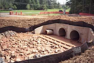


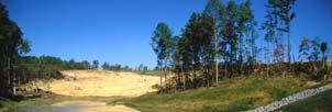


3 Example Construction Site Sediment Ponds


4 Typical Performance for Well-Designed Sediment Pond Pond Performance Dependent on Particle Characteristics v = Q A out Q out = pond outflow rate (cubic feet per second), A = pond surface area (square feet: pond length times pond width), and v = upflow velocity, or critical particle settling velocity (feet per second) 4
 in diameter and median size was about 5 µm (0.005 mm).")
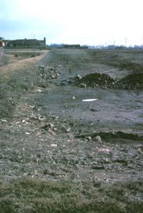
5 Typical Runoff Particle Size Distribution Measured suspended solids concentrations ranged from 100 to more than 5,000 mg/l (overall median about 4,000 mg/l). Turbidity ranged from about 00 to >50,000 NTU, with an average of about 4,000 NTU Particle sizes: 90% were smaller than about 0 µm (0.0 mm) in diameter and median size was about 5 µm (0.005 mm). Measured Birmingham construction site erosion discharges range from about 100 to 00 tons/acre/year Measured conditions: Low intensity rains (<0.5 in/hr) Moderate intensity rains (about 0.5 in/hr) High intensity rains (>1 in/hr) Suspended solids, mg/l 400,000 5,000 Particle size (median), µm Particle Settling Rates µm particle x 10 4 cm/s or 5.8 days for 1 meter 0 µm particle x 10 cm/s or 1.4 hours for 1 meter 00 µm particle cm/s or 50 sec for 1 meter 000 µm ( mm) particle 0 cm/s, or 5 sec for 1 meter Design of Wet Detention Ponds for the Control of Construction Site Sediment 1. The wet pond should have a minimum surface corresponding to land use and desired pollutant control. The following is an example of how initial size guidance values can be used: Paved area Undeveloped area Construction area Total: Land Area (acres) Pond Size Factor % 0.6% 1.5% Resulting Pond Surface Area (acres)
.")


 7.6 0.6 16.56 Total.0 18.")

6 Design of Wet Detention Ponds for the Control of Construction Site Sediment (cont.). The pond freeboard storage should be equal to the runoff associated with 1.5 inches rain for the land use and development type. The following is an example: Land Area (acres) Pond WQ Volume Factor Pond WQ Volume Paved area inches 0.66 ac-in Undeveloped area (clayey soils) Construction site (clayey soils) Total ac-in (1.5 ac-ft). The dead storage is needed to prevent scour of previously deposited material and should be at least ft deep over the sediment. Sediment storage volume is also needed and can be estimated using RUSLE for the construction site. 6
 Flow (cfs).5 Storage (ac-ft) Reqd.")


7 Selection of Outlet Control Device (this example for two small V-notch weirs) Head (ft) Flow (cfs).5 Storage (ac-ft) Reqd. area (acres) Flow (cfs) 0 Storage (ac-ft) Reqd. area (acres) < < SCS TR-55 plot used to size additional freeboard needed for emergency spillway Vs = 1.5 acre-ft Vr = 7.5 acre-ft and Vs/Vr = 0.0 for type II or III rain categories: qo/qi = 0.7 if the calculated peak discharge rate entering the pond (qi) = 8.7 cfs, the resulting peak discharge rate leaving the pond, qo, (through the water quality primary outlet plus the emergency spillway) is therefore: 0.7 (8.7) = 6. cfs 7
8 Rain and watershed characteristics for the emergency spillway design: P = 8 inches CN = 86; therefore the Ia = Q = 6. inches and Ia/P = Area (Am) = 0.01 mi (1. acres) Tc = 0 min (0. hr) The peak unit discharge rate from the tabular hydrograph method is 498 csm/in, and the peak discharge is therefore: Q peak = (498 csm/in)(0.01 mi )(6. in) = 6.7 ft /sec Also, the volume of runoff for this event is: V r = [(6. in)(1. ac)]/1 in/ft = 6.8 ac-ft The maximum desired discharge rate for this pond (for both the water quality outlet plus the emergency spillway) is given as 46.5 ft/sec. The ratio of the outlet to the inlet flow rate is therefore: q o /q i = 46.5/6.7 = 0.7 The ratio of the storage volume (V s ) to the runoff volume (V r ), for Type II rains is 0., for this ratio of outlet to inlet peak flow rates. Therefore the storage for the pond to meet this peak discharge rate goal is: V s = 0. (6.8 acre-ft) = 1.4 acre-ft The length (LW in feet) of a rectangular weir, for a given stage (HW in feet) and desired outflow rate (qo in ft /sec) can be expressed as: L = w q o 1.5.H w The desired q o for the rectangular weir is = 44. ft /sec. If the maximum stage for the emergency spillway is 1 ft, then length for the emergency spillway is: L qo =.H 44 ft / sec = w = w ( ft) ft Example Pond Design for Construction Site Sediment Control Construction area Undeveloped area Paved area Total: Area (acres) % of area needed for pond surface 1.5% Pond surface area (acres) Water quality volume (inches of runoff) Pond volume (acreinches)
9 A pond depth of ft, and approximate side slopes of 1% and a top area of 0.9 acres are used. An additional 1 ft of storage to accommodate an emergency spillway is also provided, with a maximum top area needed of about 1 acre. A 1 inch vertical riser pipe, having its opening at the normal pond water surface level, seems to be a good choice. Three feet of standing water is needed above the maximum sediment depth in order to minimize scour. In addition, sacrificial sediment storage must also be provided in the pond. R = 50 LS = 4.95 (based on typical slope lengths of 600 ft at 10% slope) k = 0.8 C = 0.5 (assuming that ¼ of the construction site area is being actively being worked, and the rest of the area is effectively protected) The calculated unit area erosion loss for this construction period is therefore about 4 tons per acre per year. Since the construction period is one-half year and the area is 7 acres, the total sediment loss is estimated to be about 4490 tons. For a loam soil, this sediment volume is about 4600 yd. The pond area at the bottom of the ft of standing water is about ½ acre, requiring about ft of sediment storage. Rain range (inches) 0.01 to to to to to to to to to to to 4.00 over events Mid Point Rain (inches) 41.5 years % of annual R in category % particulate solids removed for pond Weighted total annual particulate solids removal (%) % annual particulate solids removal Example Sizing of Sediment Pond at Construction Site the basic pond area, the live storage volume, the pond side slopes, top surface area, and dead storage volume, the selection of the primary discharge device, the additional storage volume needed for the emergency spillway, the sizing of the emergency spillway, and the sacrificial storage volume for sediment accumulation. 9
10 the basic pond area and live storage volume The following are the areas associated with each surface in the drainage area: - paved areas: 0. acres - undeveloped areas: 1. acres - construction area: acres - total site area:.4 acres Site Subarea paved area (0. acres) undeveloped area (1. acres) construction area ( acres) Total: Pond Surface Area (acres) % of 0. acres = acres 0.6% of 1. acres = acres 1.5% of acres = 0.48 acres 0.49 acres Pond Live Volume, runoff from 1.5 inches of rain fall (acre- inches of runoff) 1.1 inches x 0. acres = 0. ac-in 0. inches x 1. acres = 0.6 ac-in 0.6 inches x acres = 19. ac-in 19.8 ac-in = 1.65 ac-ft pond side slopes, top surface area, and dead storage volume 1) If ft deep: Top area: at 0.61 acres: at 0.49 acres: π πr = 1,40 ft r = 6,570 ft ( 0.49acres + X ) X = 0. 61acres r = 9 ft r = 8 ft ft = 1.65ac ft side slope = ft/(9-8 ft) = ft/10 ft = 0. = 0% too steep Therefore try different pond depths and calculate diameters and slopes: If 1 ft deep; top area =.81 acres and r = 197 ft and side slope = 1.% too shallow If ft deep; top area = 1.16 acres and r = 16 ft and side slope = 4.5% suitable, but on the low side etc.. the selection of the primary discharge device At the top of the live storage volume, this pond will have ft of stage and 1.16 acres maximum pond area: 45 o V-notch weir requires at least 1.0 acres of pond surface at feet of stage in order to provide about 90% control of sediment. 0 o V-notch weir would require only 0.7 acres, 60 o V-notch weir would require 1.4 acres. None of the rectangular weirs would be suitable, as the smallest ft weir requires at least.6 acres at feet of stage. The 45 o weir is closest to the area available and is therefore selected for this pond. Another suitable outlet structure would be an 18 drop tube structure which requires at least 1.1 acres. 10
11 the sacrificial storage volume for sediment accumulation Using RUSLE, calculate the sediment loss for the complete construction period for the site area draining to the pond: R = 50 LS = 1.8 (based on typical slope lengths of 00 ft at 5% slope) k = 0.8 C = 0.4 (assuming that 5 of the acres of the construction area is being actively worked with a C=1, and the other 7 acres of the construction area is effectively protected with a C=0.1) A = (50)(1.8)(0.8)(0.4) = 0 tons per acre per year. Since the construction period is for one year and the active construction area is acres, the total sediment loss is estimated to be about 960 tons. For a loam soil, this sediment volume is about 980 yd, or 0.8 acre-ft. The pond water surface is about 0.5 acres. With a three feet deep dead storage depth to minimize scour, the surface area at the bottom of this ft scour protection zone (and the top of the sediment storage zone), can be about 0.5 acres (about 5% underwater slope). The sacrificial storage zone can be about ft deep also, and the bottom pond area would be about 0.18 acre, as shown in the following calculations: Top of sacrificial storage area is 0.5 acres, at 0.5 acres: π r = 15,50 ft r = 70 ft Therefore, the area of the bottom of the sacrificial storage area needed to provide 0.8 acre-ft of storage, if feet deep can be approximated by: ( 0.5acres + X ) X = 0. 18acres ft = 0.8ac ft at 0.18 acres, r = 50 ft side slope = ft/(70-50 ft) = ft/0 ft = 0.15 = 15% the additional storage volume needed for the emergency spillway Therefore, this example will only consider the capacity of the emergency spillway to meet the design storm flow rate, the 5- year event. Other watershed characteristics are: watershed area: construction area ( acres), paved area (0. acres), and undeveloped area (1. acres) =.4 acres = 0.05 mi clayey (hydrologic soil group D) soils (weighted curve number = 94) time of concentration (Tc): 1 minutes (0. hours). Since the pond is at the bottom of this watershed, there is no travel time through down-gradient subwatershed areas. rain intensity for a 5-year rain for the Birmingham, AL, area, with a 15 minute time of concentration (from the local IDF curve): 6.6 inches/hour (type III rain) 11
12 - Ia for this curve number is 0.18 inches. -4-hour, 5-year rain has a total rain depth (P) of 6.9 inches. -Ia/P ratio is therefore: 0.18/6.9 = 0.019, which is much less than 0.1. Therefore the tabular hydrograph table to be used would be Exhibit III, corresponding to a Tc of 0. hour. The top segment of csm/in (cubic feet per second per square mile of watershed per inch of direct runoff) values are therefore used, corresponding to Ia/P values of 0.1, or less. The top row is also selected as there is no travel time through downstream subwatersheds. Examining this row, the largest value is 565 csm/in, occurring at 1. hours. The amount of direct runoff for a site having a CN of 94 and a 4-hr rain depth of 6.9 inches is 6. inches. The AmQ value (area in square miles times the direct runoff in inches) for this site is: (0.05 mi )(6. inches) = 0. mi -in. This value is multiplied by the csm value to obtain the peak runoff rate for this design storm: (0. mi-in)( 565 csm/in) = 18 ft /sec. The first trial for an emergency spillway will be a rectangular weir, with one foot of maximum stage. At the one foot of stage on this weir, the 45 o V-notch weir will have feet of stage. The V- notch weir will discharge 16 ft /sec at this stage. Therefore, the rectangular weir will need to handle: ft /sec = 166 ft /sec. The rectangular weir can be sized from the rectangular weir equation : qo 166 ft / sec Lw = = 5 ft.5 (.)( H ) (.)( 1) = w This may be large for this pond, so another alternative is to try for a rectangular weir having ft of maximum stage. Another alternative is to try for a rectangular weir having ft of maximum stage. At this elevation (4 ft total), the 45 o V-notch weir will discharge ft /sec. Therefore, the rectangular weir will need to handle: 18 ft /sec = 149 ft /sec. The rectangular weir can be sized from the rectangular weir equation: qo 149 ft / sec Lw = = 16 ft.5 (.)( H ) (.)( ) = w This is a suitable length, but does result in an additional foot of pond depth. For this example, the 5 foot long weir is selected. 6 Final pond profile and expected performance Pond Depth (ft from bottom of pond, the datum) Surface Area at Depth (acres) Pond Storage below Elevation (calculate d by Detpond) (acre-ft) Pond slope notes between this elevation and next highest noted elevation - the pond bottom (datum) must be 0 acres for the routing calculations 15% the area close to the bottom can be the calculated/desired pond bottom area. This is the bottom of the sacrificial storage area for the sediment 5% this is the top of the sacrificial storage area for the sediment 4.5% this is the bottom of the dead storage area, at least feet above the pond bottom (this is 6 feet above the absolute bottom, but is feet above the top of the maximum sediment accumulation depth) 1

13 Final pond profile (continued) Pond Depth (ft from bottom of pond, the datum) Surface Area at Depth (acres) Pond Storage below Elevation (calculate d by Detpond) (acre-ft) Pond slope between this elevation and next highest noted elevation 4.5% 4.5% - notes this is the bottom (invert) of the water quality outlet structure (and live storage volume), a 45 o V-notch weir this is the top of live storage volume, and the bottom of the emergency spillway, a 5 ft long rectangular weir 1 foot of freeboard above maximum expected water depth, the top of the pond The pond performance for a 0 year period of rain (,46 events, ranging from 0.01 to 1.6 inches) was calculated using Detpond. During these 0 years, the expected maximum pond stage is slightly more 8 ft. The emergency spillway was used a total of four times in this period. The flow-weighted particulate solids removal rate was about 9%. Maximum Average Flow-weighted Average Median Standard Deviation COV Max. Pond Stage (ft) n/a Event Inflow Volume (ac-ft) 0.10 n/a Event Flushing Ratio Flowweighted Particle Size (µm) 6.8 n/a Partic. Solids Removed (%) 100 n/a Therefore, this pond is likely over-designed for these conditions and could be somewhat reduced in area and depth. Use of Chemical-Assisted Sedimentation Auckland Regional Council, New Zealand 1


 6,00 5,100 1,69 749 14,800 18,700 4,00 16,900 Flow (L/sec) Outflow 8 6 0.4.0 SS (mg/l) 144 40 51 56 966 67 59 SS Reduction (%) 99.")
14 Polyaluminum Chloride (PAC) was a more suitable choice, especially for clayey soil conditions, than alum and other tested coagulants. The overall suspended solids treatment efficiency of PACtreated ponds has been between % for ponds having good physical designs. Lower treatment efficiencies have occurred where there have been problems with decants not operating properly, or physical problems such as multiple inflow points, high inflow energy, and poor separation of inlets and outlets. Example Performance Data for PAC-assisted Settling OVR E OVR E 800E 800E B1 Gully B1 Gully Pond Mason s Rd Mason s Rd Flow (L/sec) Inflow SS (mg/l) 6,00 5,100 1, ,800 18,700 4,00 16,900 Flow (L/sec) Outflow SS (mg/l) SS Reduction (%) Filter Fences Woven and non-woven fabric varieties Act as small detention ponds by ponding water behind the barrier Frequently badly installed and maintained Measured moderate SS performance (0 to 50% removals in the laboratory, much less under actual field conditions). 14


")


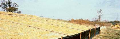


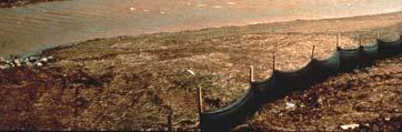
15 Perimeter Filter Fences (little water flowing towards barrier) Filter Fabric Fences at Toe of Slope Multiple fence lines and a tree barrier: 15


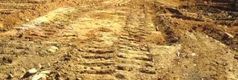
16 Filter Fence Performance at Construction Sites Filter fences also act as sedimentation devices for trapping eroded material. Their performance has been disappointing during monitoring projects: Inadequate filter fabric material splicing (splits and tears) Fence failure due to sustained over-topping Unrepaired holes in fabric Flow beneath fabric due to inadequate trenching Over-loaded Filter Fabrics Water Flowing Under or Around Filter Fabrics 16


17 Straw Bale Barriers Seldom Effective Filter fences act as sedimentation devices by trapping material. Their performance can be calculated using the upflow procedure. The discharge rate is based on the water depth and the unit area flow rate of the fabric and the surface area is based on the water depth and slope. Water ponds behind fabric, small amount is filtered on fabric Measured Silt Fence Performance during Alabama Tests (about 54% reductions) Total Suspended Solids Mean + Std. Error Control Fence Nothing 17
18 Summary of Local Silt Fence Tests Silt fences in good condition remove 1/ to 1/ of the particles in the runoff. Runoff below silt fences contains more than 100 times more particles than runoff from undisturbed vegetation. Even with silt fences, the suspended solids content in the construction site runoff was found to be very high with an average of about,000 mg/l, while the undisturbed locations had runoff concentrations less than 100 mg/l. Silt fences, at best, are only partially effective in removing particulate matter from runoff during intense rains. Pressure Force on Filter Fences The pressure equation can be used to calculate the forces acting on filter fences. The following calculation shows the resisting force needed for a 10 ft span of filter fence with ft of standing water: ( 6.4lb / ft )( 0 ft )( ft) F1 = = 148lb Basically, the forces acting on a filter fence can be very large and the filter fence stake systems must be selected to withstand this force. In addition, the resisting forces of the soil also act on the fence stake to hold it upright, and also needs to be considered. Wet and soft soils may need long stakes driven deeply in the ground to resist this pressure. AL Silt Fence Specifications Tensile Strength (Lbs. Min. ASTM D-46) Elongation (% Max.) (ASTM D- 46) AOS (Apparent Opening Size) (Max. Sieve Size) (ASTM D-4751) Flow Rate (Gal/Min/Sq. Ft.) (GDT- 87) Ultraviolet Stability (ASTM D-46 after 00 hours weathering in accordance with ASTM D-455) Bursting Strength (PSI Min.) (ASTM D-786 Diaphragm Bursting Strength Tester) Minimum Fabric Width (Inches) Type A Warp 60 Fill no Type B Warp 10 Fill no Type C Warp 10 Fill no AL Slope Limitations for Silt Fence Land Slope (Percent) < to 5 5 to to 0* >0 Maximum Slope Length Above Fence (Feet)
19 Minimum Length Type A Type B Type C Gauge Wire Staples Nails 4 4 Steel Soft Wood Oak Steel Soft Wood Oak Steel 17 minimum 14 minimum Type of Post Crown ¾ wide Length 1 Size of Post 1.lb/ft minimum diameter or X4 1.5 X lb/ft minimum diameter or X 1 X lb/ft minimum Legs ½ long Button Heads ¾ long Staples/P ost 5 minimum Nail/Post 4 minimum Homework for Chapter 6 1) Identify locations for silt fences on your construction site. Make sure that the slope and length specifications are met. Determine the type of silt fence needed for each area. ) Determine the expected performance of the silt fence in controlling sediment for each silt fence. ) Locate the most suitable location(s) for a sediment pond for your site. Prepare a preliminary design for at least one pond, and discuss the suitability of ponds for the control of sediment at your site. 19
Module 6 Temporary Pond and Silt Fence. Noboru Togawa. Presented to: Dr. Pitt Construction Site Erosion Control
 Module 6 Temporary Pond and Silt Fence by Presented to: Dr. Pitt Construction Site Erosion Control Department of Civil, Construction, and Environmental Engineering The University of Alabama Tuscaloosa,
Common Stormwater Controls
 Module 12: Detention Pond Design for Water Quality Improvement Robert Pitt Department of Civil, Construction, and Environmental Engineering University of Alabama Presentation Contents Small-scale settling
CE 585 Construction Site Erosion Control The University of Alabama Tuscaloosa, AL. New Chevrolet and Cadillac Dealership Jasper, AL
 CE 585 Construction Site Erosion Control The University of Alabama Tuscaloosa, AL New Chevrolet and Cadillac Dealership Jasper, AL Andrew Kennedy Homework #6 July 24, 2007 0 Table of Contents Table of
Detention Pond Design Considering Varying Design Storms. Receiving Water Effects of Water Pollutant Discharges
 Detention Pond Design Considering Varying Design Storms Land Development Results in Increased Peak Flow Rates and Runoff Volumes Developed area Robert Pitt Department of Civil, Construction and Environmental
SC-01 Surface Outlet and Baffle Sediment Basin
 Greenville County Technical Specification for: SC-01 Surface Outlet and Baffle Sediment Basin 1.0 Surface Outlet and Baffle Sediment Basin This Specification contains requirements for the design and construction
Manual for Erosion and Sediment Control Updates
 Manual for Erosion and Sediment Control Updates Chapter 1 - The Erosion and Sedimentation Act of 1975 Minor revisions were made to content Existing pictures were replaced with new ones Chapter 2 Sediment
Typical Local Erosion Control Requirements (Storm Water Management Authority, Inc.)
") Module 2: Selection of Controls and Site Planning for Construction Site Erosion Prevention Robert Pitt Department of Civil, Construction, and Environmental Engineering University of Alabama Tuscaloosa,
Module 2: Selection of Controls and Site Planning for Construction Site Erosion Prevention Robert Pitt Department of Civil, Construction, and Environmental Engineering University of Alabama Tuscaloosa,
Treatability Testing and the Development of Stormwater
 Module 4b: Sedimentation and Wet Detention Ponds Robert Pitt Department of Civil and Environmental Engineering University of Alabama Presentation Contents Stormwater treatability and enhancements to improve
Module 3: Rainfall and Hydrology for Construction Site Erosion Control
 Module 3: Rainfall and Hydrology for Construction Site Erosion Control Robert Pitt Department of Civil, Construction, and Environmental Engineering University of Alabama Tuscaloosa, AL Rainfall and Hydrology
Appendix C.1. Design Example 1 Shallow Wetland (W-1)
") Appendix C.1 Design Example 1 Shallow Wetland (W-1) Design Example 1 Shallow Wetland (W-1) The following example demonstrates the process for the design of a shallow wetland (W-1) BMP. Site Specific Data
Appendix C.1 Design Example 1 Shallow Wetland (W-1) Design Example 1 Shallow Wetland (W-1) The following example demonstrates the process for the design of a shallow wetland (W-1) BMP. Site Specific Data
RETENTION BASIN EXAMPLE
 -7 Given: Total Tributary Area = 7.5 ac o Tributary Area within Existing R/W = 5.8 ac o Tributary Area, Impervious, Outside of R/W = 0.0 ac o Tributary Area, Pervious, Outside of R/W = 1.7 ac o Tributary
Module 3 and Module 4 Watershed Analysis and RUSLE Calculation. Noboru Togawa. Presented to: Dr. Pitt Construction Site Erosion Control
 Module 3 and Module 4 Watershed Analysis and RUSLE Calculation by Presented to: Dr. Pitt Construction Site Erosion Control Department of Civil, Construction, and Environmental Engineering The University
INFLOW DESIGN FLOOD CONTROL SYSTEM PLAN PLANT GASTON GYPSUM POND ALABAMA POWER COMPANY
 INFLOW DESIGN FLOOD CONTROL SYSTEM PLAN PLANT GASTON GYPSUM POND ALABAMA POWER COMPANY Section 257.82 of EPA s regulations requires the owner or operator of an existing or new CCR surface impoundment or
Detention Pond Design and Analysis. CE 378 Water Resources Engineering. Contents
 R. Pitt April 12, 2004 Detention Pond Design and Analysis CE 378 Water Resources Engineering Contents Introduction...1 Expected Detention Pond Performance...2 Potential Detention Pond Problems...3 Wet
2-16 EROSION, SEDIMENT & STORM WATER CONTROL REGULATIONS APPENDIX B1
 2-16 EROSION, SEDIMENT & STORM WATER CONTROL REGULATIONS APPENDIX B1 There are three ways to accomplish urban soil erosion and sedimentation control: Allow erosion to take place and then control sediment
Example 1: Pond Design in a residential development (Water Quantity calculations for a Wet Pond and Wet Extended Detention Pond)
") Chapter 10 Design Examples Example 1: Pond Design in a residential development (Water Quantity calculations for a Wet Pond and Wet Extended Detention Pond) Example 2: Filter Design in a commercial development
Chapter 10 Design Examples Example 1: Pond Design in a residential development (Water Quantity calculations for a Wet Pond and Wet Extended Detention Pond) Example 2: Filter Design in a commercial development
Extended Detention Basin Design
 Extended Detention Basin Design 1 Extended Detention 2 Ohio Department of Transportation 1 Extended Detention Basin L&D Vol. 2 Section 1117.3 Provides quality and quantity treatment 3 Extended Detention
INFLOW DESIGN FLOOD CONTROL SYSTEM PLAN PLANT GREENE COUNTY ASH POND ALABMA POWER COMPANY
 INFLOW DESIGN FLOOD CONTROL SYSTEM PLAN PLANT GREENE COUNTY ASH POND ALABMA POWER COMPANY Section 257.82 of EPA s regulations requires the owner or operator of an existing or new CCR surface impoundment
Bowling Green, Kentucky Stormwater Best Management Practices (BMPs) Sediment Management Practices (SMPs) Activity: Temporary Inlet Protection (TIP)
 Sediment Management Practices (SMPs) Activity: Temporary Inlet Protection (TIP)") Bowling Green, Kentucky Stormwater Best Management Practices (BMPs) Sediment Management Practices (SMPs) Activity: Temporary Inlet Protection (TIP) SMP-11 PLANNING CONSIDERATIONS: Design Life: 1 yr Acreage
Bowling Green, Kentucky Stormwater Best Management Practices (BMPs) Sediment Management Practices (SMPs) Activity: Temporary Inlet Protection (TIP) SMP-11 PLANNING CONSIDERATIONS: Design Life: 1 yr Acreage
INFLOW DESIGN FLOOD CONTROL SYSTEM PLAN PLANT BARRY ASH POND ALABAMA POWER COMPANY
 INFLOW DESIGN FLOOD CONTROL SYSTEM PLAN PLANT BARRY ASH POND ALABAMA POWER COMPANY Section 257.82 of EPA s regulations requires the owner or operator of an existing or new CCR surface impoundment or any
APPENDIX A - SURFACE OUTLET AND BAFFLE SEDIMENT BASINS
 APPENDIX A - SURFACE OUTLET AND BAFFLE SEDIMENT BASINS AND MULTIPURPOSE BASINS This Appendix contains requirements for the design, materials, equipment, and construction of temporary Surface Outlet and
INFLOW DESIGN FLOOD CONTROL SYSTEM PLAN 40 C.F.R. Part PLANT MCINTOSH ASH POND 1 GEORGIA POWER COMPANY
 INFLOW DESIGN FLOOD CONTROL SYSTEM PLAN 40 C.F.R. Part 257.82 PLANT MCINTOSH ASH POND 1 GEORGIA POWER COMPANY EPA s Disposal of Coal Combustion Residuals from Electric Utilities Final Rule (40 C.F.R. Part
Block and gravel filters can be used where velocities are higher. Reduces the amount of sediment leaving the site.
 INLET PROTECTION From Massachusetts Erosion and Sediment Control Guidelines for Urban and Suburban Areas http://www.state.ma.us/dep/brp/stormwtr/files/esfull.pdf Definition: A sediment filter or an excavated
Design of Stormwater Wetlands
 Hydraulic & Hydrologic Stormwater Engineering Design of Stormwater Wetlands Jon Hathaway, EI Extension Associate NCSU Bio. And Ag. Engineering 6 Step Process 1. Watershed Analysis (Runoff Volume and Peak
INITIAL RUN-ON AND RUN-OFF CONTROL PLAN 40 C.F.R. PART 257
 INITIAL RUN-ON AND RUN-OFF CONTROL PLAN 40 C.F.R. PART 257.81 HUFFAKER ROAD (PLANT HAMMOND) PRIVATE INDUSTRIAL LANDFILL (HUFFAKER ROAD LANDFILL) GEORGIA POWER COMPANY EPA s Disposal of Coal Combustion
INITIAL RUN-ON AND RUN-OFF CONTROL PLAN 40 C.F.R. PART 257
 INITIAL RUN-ON AND RUN-OFF CONTROL PLAN 40 C.F.R. PART 257.81 PLANT BOWEN PRIVATE INDUSTRY SOLID WASTE DISPOSAL FACILITY (ASH LANDFILL) GEORGIA POWER COMPANY EPA s Disposal of Coal Combustion Residuals
INFLOW DESIGN FLOOD CONTROL SYSTEM PLAN 40 C.F.R. PART PLANT YATES ASH POND 3 (AP-3) GEORGIA POWER COMPANY
 GEORGIA POWER COMPANY") INFLOW DESIGN FLOOD CONTROL SYSTEM PLAN 40 C.F.R. PART 257.82 PLANT YATES ASH POND 3 (AP-3) GEORGIA POWER COMPANY EPA s Disposal of Coal Combustion Residuals from Electric Utilities Final Rule (40 C.F.R.
INFLOW DESIGN FLOOD CONTROL SYSTEM PLAN 40 C.F.R. PART 257.82 PLANT YATES ASH POND 3 (AP-3) GEORGIA POWER COMPANY EPA s Disposal of Coal Combustion Residuals from Electric Utilities Final Rule (40 C.F.R.
SECTION B. Prevention of sedimentation of waterways, open drainage ways, and storm and sanitary sewers due to construction activities.
 SECTION 01 5713 TEMPORARY EROSION AND SEDIMENT CONTROL PART 1 GENERAL 1.01 SECTION INCLUDES A. Prevention of erosion due to construction activities. B. Prevention of sedimentation of waterways, open drainage
SE-6 GRAVEL BAG BERM. Objectives. Potential Alternatives
 Objectives Erosion Control - EC Sediment Control - SE Tracking Control - TC Wind Erosion Control - WE Non-Storm Water Management - NS Materials and Waste Management - WM DESCRIPTION AND PURPOSE A gravel
Hydrology for Drainage Design. Design Considerations Use appropriate design tools for the job at hand:
 Hydrology for Drainage Design Robert Pitt Department of Civil and Environmental Engineering University of Alabama Tuscaloosa, AL Objectives for Urban Drainage Systems are Varied Ensure personal safety
Sediment Basin. Fe= (Depends on soil type)
") 3.9 Sediment Control Description: A sediment basin is an embankment with a controlled outlet that detains stormwater runoff, resulting in the settling of suspended sediment. The basin provides treatment
3.9 Sediment Control Description: A sediment basin is an embankment with a controlled outlet that detains stormwater runoff, resulting in the settling of suspended sediment. The basin provides treatment
Introduction to Storm Sewer Design
 A SunCam online continuing education course Introduction to Storm Sewer Design by David F. Carter Introduction Storm sewer systems are vital in collection and conveyance of stormwater from the upstream
Construction Site Erosion Control and Phase II of the Stormwater Permit Program
 Construction Site Erosion Control and Phase II of the Stormwater Permit Program Robert Pitt Department of Civil, Construction, and Environmental Engineering University of Alabama Tuscaloosa, AL In Georgia,
Standards for Soil Erosion and Sediment Control in New Jersey May 2012 STANDARD FOR SLOPE PROTECTION STRUCTURES. Definition
 STANDARD FOR SLOPE PROTECTION STRUCTURES Definition Structures to safely conduct surface runoff from the top of a slope to the bottom of the slope. Purpose The purpose of this practice is to convey storm
Construction Site Erosion Control and Phase II of the Stormwater Permit Program
 Construction Site Erosion Control and Phase II of the Stormwater Permit Program Robert Pitt Department of Civil and Environmental Engineering University of Alabama Tuscaloosa, AL Some Features of Phase
Figure Inlet protection (Source: Minnesota DOT)
") 3.9 INLET PROTECTION Figure 3.14. Inlet protection (Source: Minnesota DOT) Overview Description: A manufactured protective device or barrier used to trap sediment at a storm drain surface or curb inlet.
3.9 INLET PROTECTION Figure 3.14. Inlet protection (Source: Minnesota DOT) Overview Description: A manufactured protective device or barrier used to trap sediment at a storm drain surface or curb inlet.
Surface Skimmer and Baffle Sediment Basins, Modeling the Benefits
 Surface Skimmer and Baffle Sediment Basins, Modeling the Benefits J.P. Johns, PE Woolpert Ray Vaughan Stormwater Manager SCDOT Brandon Wagner -Woolpert Background o SCDOT sediment basin design required
Water Resources Management Plan
 P L Y M O U T H M I N N E S O T A Appendix D: The developed a to analyze and minimize the impact of existing and future development on the City s natural resources. It is important to the City to have
4.4.9 Sand Filter. Estimated Pollutant Removal Efficiency Rates Description and Benefits
 4.4.9 Sand Filter 4.4.9.1 Description and Benefits A sand filter is a device that allows stormwater to percolate down through sand layers and possibly a topsoil layer. Common usage areas for this type
Chapter 5.5 Inlets, Outlets, and Flow Control
 Chapter 5.5 Inlets, Outlets, and Flow Control There are common structural elements of SCMs that are designed to safely route water. Engineered flow control devices are used to effectively route water at
INITIAL INFLOW DESIGN FLOOD CONTROL SYSTEM PLAN PLANT MCMANUS ASH POND A (AP-1) 40 CFR
 40 CFR") INITIAL INFLOW DESIGN FLOOD CONTROL SYSTEM PLAN PLANT MCMANUS ASH POND A (AP-1) 40 CFR 257.82 EPA s Disposal of Coal Combustion Residuals from Electric Utilities Final Rule (40 C.F.R. Part 257 and Part
INITIAL INFLOW DESIGN FLOOD CONTROL SYSTEM PLAN PLANT MCMANUS ASH POND A (AP-1) 40 CFR 257.82 EPA s Disposal of Coal Combustion Residuals from Electric Utilities Final Rule (40 C.F.R. Part 257 and Part
LAKE COUNTY HYDROLOGY DESIGN STANDARDS
 LAKE COUNTY HYDROLOGY DESIGN STANDARDS Lake County Department of Public Works Water Resources Division 255 N. Forbes Street Lakeport, CA 95453 (707)263-2341 Adopted June 22, 1999 These Standards provide
Construction Site Erosion Control and Phase II of the Stormwater Permit Program
 Construction Site Erosion Control and Phase II of the Stormwater Permit Program Robert Pitt Department of Civil, Construction, and Environmental Engineering University of Alabama Tuscaloosa, AL In Georgia,
Particulate Transport in Grass Swales
 Particulate Transport in Grass Swales Robert Pitt, P.E., Ph.D., DEE and S. Rocky Durrans, P.E., Ph.D. Department of Civil, Construction, and Environmental Engineering The University of Alabama Yukio Nara
Suitable Applications Where concentrated flow of surface runoff must be conveyed down a slope in order to prevent erosion.
 Categories EC Erosion Control SE Sediment Control TC Tracking Control WE Wind Erosion Control Non-Stormwater NS Management Control Waste Management and WM Materials Pollution Control Legend: Primary Objective
WQ-06 SAND FILTER. 1.0 Sand Filter. Greenville County Technical Specification for: 1.1 Description
 Greenville County Technical Specification for: WQ-06 SAND FILTER 1.0 Sand Filter 1.1 Description Sand Filters remove pollutants through sedimentation and filtration within the sand. The primary components
WinTR-55 Small Watershed Hydrology
 WinTR-55 Small Watershed Hydrology Intermediate WinTR-55 Training Modeling Watersheds with Structures SEE NOTES AT CLASS EXERCISE #4. 1 Course Outline Overview Review of Hydrology Terms Modeling Single
EROSION AND SEDIMENT CONTROL STANDARDS CITY OF OVERLAND PARK DRAFT
 A. Authority EROSION AND SEDIMENT CONTROL STANDARDS CITY OF OVERLAND PARK DRAFT 06.15.2005 As set forth in the Overland Park Municipal Code (OPMC), Chapter 16.200, the Director of Planning and Development
Chapter 6 Sand Filtration Treatment Facilities
 Sand Filtration Treatment Facilities 6.1 Purpose This chapter presents criteria for the design, construction and maintenance of runoff treatment sand filters. Treatment sand filters are used to collect,
York County STORMWATER LUNCH & LEARN
 York County STORMWATER LUNCH & LEARN TOPICS Points of Exposure SWPPP's NOT's Construction Sequence Permanent BMP's Basin Details Major and Minor Modifications Construction Buffers Stabilization Questions
ACTIVITY: Silt Fence ES 14
 Targeted Constituents Significant Benefit Partial Benefit Low or Unknown Benefit Sediment Heavy Metals Floatable Materials Oxygen Demanding Substances Nutrients Toxic Materials Oil & Grease Bacteria &
4.4.6 Underground Detention
 4.4.6 Underground Detention Limited Application Water Quality BMP Description: Detention storage located in underground pipe systems or vaults designed to provide water quantity control through detention
Storm Drain Inlet Protection
 Categories EC Erosion Control SE Sediment Control TC Tracking Control WE Wind Erosion Control Non-Stormwater NS Management Control Waste Management and WM Materials Pollution Control Legend: Primary Category
Environmental Design Group
 SEDIMENT CONTROL DURING CONSTRUCTION, STORMWATER MANAGEMENT AND POST CONSTRUCTION BMP REPORT for Hudson Salt Storage and Bus Garage 5810 Hudson Drive HUDSON, OHIO SUMMIT COUNTY Prepared by Environmental
This silt fence system is composed of geotextile filter fabric and steel posts.
 Supplemental Technical Specification for SILT FENCE SYSTEMS SCDOT Designation: SC-M-815-2 (03/08) 1.0 Silt Fence Systems This Supplemental Specification replaces Sections 815.2.5 and 815.4.6, Silt Fences,
EROSION CONTROL GENERAL NOTES EC JAN 2017 C.B.
 EROSION CONTROL GENERAL NOTES EC - 000 EROSION CONTROL GENERAL NOTES EC - 001 INSTALL TEMPORARY DRIVEWAY CULVERT IF THERE IS A ROADSIDE DITCH PRESENT EXISTING PAVEMENT OR APPROVED ACCESS POINT OR AS PRACTICABLE
Straw Bale Barrier. - Along the face and at grade breaks of exposed and erodible slopes to shorten slope length and spread runoff as sheet flow
 Straw Bale Barrier SE-9 Objectives EC Erosion Control SE Sediment Control TR Tracking Control WE Wind Erosion Control Non-Stormwater NS Management Control Waste Management and WM Materials Pollution Control
This silt fence system is composed of geotextile filter fabric and steel posts.
 Supplemental Technical Specification for SILT FENCE SYSTEMS SCDOT Designation: SC-M-815-2 (7/18) 1.0 Silt Fence Systems This Supplemental Specification replaces Sections 815.2.5 and 815.4.6, Silt Fences,
Final Drainage Report
 Thornton Electric Substation Project Final Drainage Report December 14, 2016 DRAFT Prepared for: Xcel Energy, 1800 Larimer Street, Suite 400, Denver, Colorado 80202 Prepared by: 350 Indiana Street, Suite
6.5 Extended Detention Basin
 6.5 Extended Detention Basin Figure 6-22: Extended Detention Basin. Photograph courtesy of Bill Southard (DES Architects and Engineers) Best uses Detain low flows Can be expanded to detain peak flows Sedimentation
Results shown on 'Detailed Summary' tab
 Fill in site's Pre Development parameters on 'Pre' tab (Site Area, Drainage Area, Impervious Area, CNpre, tc) Prior to using BSD or BMP practices, fill in site's Post Development parameters on 'Post' tab
NEW CASTLE CONSERVATION DISTRICT. through. (Name of Municipality) PLAN REVIEW APPLICATION DRAINAGE, STORMWATER MANAGEMENT, EROSION & SEDIMENT CONTROL
 PLAN REVIEW APPLICATION DRAINAGE, STORMWATER MANAGEMENT, EROSION & SEDIMENT CONTROL") NEW CASTLE CONSERVATION DISTRICT through (Name of Municipality) PLAN REVIEW APPLICATION DRAINAGE, STORMWATER MANAGEMENT, EROSION & SEDIMENT CONTROL Office use only: Received by Municipality: Received by
NEW CASTLE CONSERVATION DISTRICT through (Name of Municipality) PLAN REVIEW APPLICATION DRAINAGE, STORMWATER MANAGEMENT, EROSION & SEDIMENT CONTROL Office use only: Received by Municipality: Received by
Shelbyville, Kentucky Stormwater Best Management Practices (BMPs) Stormwater Pollution Treatment Practices (Structural) DRAFT
 Stormwater Pollution Treatment Practices (Structural) DRAFT") Shelbyville, Kentucky Stormwater Best Management Practices (BMPs) Stormwater Pollution Treatment Practices (Structural) Activity: Infiltration Systems PLANNING CONSIDERATIONS: Design Life: Short IS Acreage
Shelbyville, Kentucky Stormwater Best Management Practices (BMPs) Stormwater Pollution Treatment Practices (Structural) Activity: Infiltration Systems PLANNING CONSIDERATIONS: Design Life: Short IS Acreage
SECTION EROSION AND SEDIMENTATION CONTROLS
 SECTION 312500 PART 1 GENERAL 1.01 GENERAL REQUIREMENTS A. Attention is directed to the CONTRACT AND GENERAL CONDITIONS and all Sections within DIVISION 01 - GENERAL REQUIREMENTS which are hereby made
BMP-5. A temporary sediment barrier consisting of a synthetic filter fabric stretched across and attached to supporting posts and entrenched.
 BMP-5 BMP: SILT FENCE Definition A temporary sediment barrier consisting of a synthetic filter fabric stretched across and attached to supporting posts and entrenched. Purposes To intercept and detain
Pre-Treatment Bioretention Cells Bioswales IOWA STORMWATER MANAGEMENT MANUAL DECEMBER 16, 2015
 Pre-Treatment Bioretention Cells Bioswales IOWA STORMWATER MANAGEMENT MANUAL DECEMBER 16, 2015 Urban Runoff Background How we got here What Problem?? Provenance of the Problem Unified Sizing Criteria What
Inlet Protection. Fe= (Depends on soil type)
") 3.4 DESIGN CRITERIA: KEY CONSIDERATIONS Evaluate drainage patterns to ensure inlet protection will not cause flooding of roadway, property or structures Never block entire inlet opening Size according
3.4 DESIGN CRITERIA: KEY CONSIDERATIONS Evaluate drainage patterns to ensure inlet protection will not cause flooding of roadway, property or structures Never block entire inlet opening Size according
How Climate Change Impacts Urban Runoff and Water Quality Design
 How Climate Change Impacts Urban Runoff and Water Quality Design by J. C. Hayes, C. Privette, III and S. J. Klaine AWRA Conference Anchorage, AK May 4-7, 2009 Presentation Outline Introduction: Why manage
Dry Swale Wet Swale Grass Channel Dry Well Permeable Pavement Bioretention DESIGN ELEMENTS
 FACILITY ID: DATE: / / ASSESSED BY: NAME: ADDRESS: PHOTO IDS: SECTION 1- BACKGROUND INFORMATION (GIS) BMP TYPE : Dry Detention Pond Extended Detention Pond Wet Pond Filter (specify: ) Infiltration (specify:
City of Doral 8401 NW 53 rd Ter. Doral, FL 33166
 City of Doral 8401 NW 53 rd Ter. Doral, FL 33166 Project Address: (305) 593-6700 Permit Number: National Pollution Discharge Elimination System (NPDES) Construction Site Erosion and Sedimentation Control
SC-07 STORM DRAIN INLET PROTECTION
 Greenville County Technical Specification for: SC-07 STORM DRAIN INLET PROTECTION 1.0 Storm Drain Inlet Protection 1.1 Description Provide Storm Drain Inlet Protection at all existing and newly installed
Straw Bale Barrier. Parallel to a roadway to keep sediment off paved areas
 Categories EC Erosion Control SE Sediment Control TC Tracking Control WE Wind Erosion Control Non-Stormwater NS Management Control Waste Management and WM Materials Pollution Control Legend: Primary Objective
PART 1 GENERAL REQUIREMENTS
 PART 1 GENERAL REQUIREMENTS Contract Closeout Plan 110 Arrow diagram for project close-out...3 Erosion Control 121 Straw bale barrier... 5 122 Silt fence... 7 123 Diversion dike... 9 124 Inlet protection...
Treatment Volume: Curve Numbers. Composite CN or Not? Treatment Volume: Curve Numbers. Treatment Volume: Calculation. Treatment Volume: Calculation
 Stormwater Engineering Bioretention Design Bill Hunt, PE, Ph.D. Extension Specialist & Assistant Professor NCSU-BAE www.bae.ncsu.edu/stormwater Bioretention Design Six Step Process 1 Determine Volume to
Installation and Maintenance of Erosion Control BMPs
 Installation and Maintenance of Erosion Control BMPs Or Common BMPs Applications Specifications Installation Problems Maintenance Utility Design Professionals Clarifications, proactive problem solving
Index. outlet protection Rev. 12/93
 6 Index outlet protection level spreader outlet stabilization structure 6.40.1 6.41.1 Rev. 12/93 Practice Standards and Specifications 6.40 level spreader Definition Purpose Conditions Where Practice Applies
Dawson County Public Works 25 Justice Way, Suite 2232, Dawsonville, GA (706) x 42228
 x 42228") Dawson County Public Works 25 Justice Way, Suite 2232, Dawsonville, GA 30534 (706) 344-3500 x 42228 DAWSON COUNTY STORM WATER REVIEW CHECKLIST Project Name: Property Address: Engineer: Fax #/Email: Date:
Dawson County Public Works 25 Justice Way, Suite 2232, Dawsonville, GA 30534 (706) 344-3500 x 42228 DAWSON COUNTY STORM WATER REVIEW CHECKLIST Project Name: Property Address: Engineer: Fax #/Email: Date:
DESIGNING AN EFFECTIVE SCS BY TREATING SEDIMENT WITH POLYMERS BIOGRAPHICAL SKETCH ABSTRACT
 DESIGNING AN EFFECTIVE SCS BY TREATING SEDIMENT WITH POLYMERS by Jerald S. Fifield, Ph.D., CISEC, CPESC HydroDynamics Incorporated P.O. Box 1327 Parker, CO 80134 Phone: 303-841-0377 Fax: 303-841-6386 hdi@ecentral.com
Report. Inflow Design Flood Control System Plan St. Clair Power Plant St. Clair, Michigan. DTE Energy Company One Energy Plaza, Detroit, MI
 Report Inflow Design Flood Control System Plan St. Clair Power Plant St. Clair, Michigan DTE Energy Company One Energy Plaza, Detroit, MI October 14, 2016 NTH Project No. 62-160047-04 NTH Consultants,
Grass Channel STORMWATER MANAGEMENT SUITABILITY KEY CONSIDERATIONS
 4.0 Structural Stormwater Control Description: Vegetated open channels designed to filter stormwater runoff and meet velocity targets for the water quality design storm and the Streambank Protection storm
Table 1: Minimum Perimeter Control Performance Requirements. Physical Property* Test Method Required Value
 Supplemental Technical Specification for PERIMETER CONTROL SCDOT Designation: SC-M-815-17 (08/13) 1.0 Perimeter Control This Supplemental Technical Specification maybe used as an alternative to Sections
CVEN 339 Summer 2009 Final Exam. 120 minutes allowed. 36 Students. No curve applied to grades. Median 70.6 Mean 68.7 Std. Dev High 88 Low 24.
 CVEN 339 Final Exam 120 minutes allowed 36 Students No curve applied to grades Median 70.6 Mean 68.7 Std. Dev. 13.7 High 88 Low 24.5 Name: CVEN 339 Water Resources Engineering Summer Semester 2009 Dr.
Submittal Requirements. Post Construction Verification Document Plan Requirements
 Submittal Requirements Post Construction Verification Document survey plan in accordance with the items of this Checklist Supporting calculations in accordance with the items of this Checklist A copy of
4.4.5 Grassed Swale (also known as Enhanced Swale or Biofiltration Swale)
") Signs of trespass or unauthorized traffic Sediment buildup Additionally, a program of regular monitoring of the aquatic environment for a permanent wet detention basin should be established to allow for
Signs of trespass or unauthorized traffic Sediment buildup Additionally, a program of regular monitoring of the aquatic environment for a permanent wet detention basin should be established to allow for
INFLOW DESIGN FLOOD CONTROL SYSTEM PLAN 40 C.F.R. PART PLANT DANIEL ASH POND B MISSISSIPPI POWER COMPANY
 INFLOW DESIGN FLOOD CONTROL SYSTEM PLAN 40 C.F.R. PART 257.82 PLANT DANIEL ASH POND B MISSISSIPPI POWER COMPANY EPA s Disposal of Coal Combustion Residuals from Electric Utilities Final Rule (40 C.F.R.
SITE DESIGN ENGINEERING, LLC. 11 Cushman Street, Middleboro, MA P: F:
 INTRODUCTION This drainage report was prepared for the proposed site re-development at in Burlington, Massachusetts. The project site is approximately 1.05± acres consisting of approximately 70% impervious
Chapter H. Introduction to Surface Water Hydrology and Drainage for Engineering Purposes
 Chapter H. Introduction to Surface Water Hydrology and Drainage for Engineering Purposes As seen in Figure H.1, hydrology is a complex science that deals with the movement of water between various stages
1. Overview 2 2. Definitions 2 3. Laboratory Testing Criteria 2. A. Laboratory Qualifications 2. B. Analysis of TSS Samples 2. C.
 New Jersey Department of Environmental Protection Laboratory Protocol to Assess Total Suspended Solids Removal by a Hydrodynamic Sedimentation Manufactured Treatment Device January 25, 2013 Contents 1.
Rock Sock (RS) Rock Sock height.
 Rock Sock height.") Rock Sock (RS) SC-5 Description A rock sock is constructed of gravel that has been wrapped by wire mesh or a geotextile to form an elongated cylindrical filter. Rock socks are typically used either as
Rock Sock (RS) SC-5 Description A rock sock is constructed of gravel that has been wrapped by wire mesh or a geotextile to form an elongated cylindrical filter. Rock socks are typically used either as
E. STORMWATER MANAGEMENT
 E. STORMWATER MANAGEMENT 1. Existing Conditions The Project Site is located within the Lower Hudson Watershed. According to the New York State Department of Environmental Conservation (NYSDEC), Lower Hudson
Report. Inflow Design Flood Control System Plan Belle River Power Plant East China, Michigan. DTE Energy Company One Energy Plaza, Detroit, MI
 Report Inflow Design Flood Control System Plan Belle River Power Plant East China, Michigan DTE Energy Company One Energy Plaza, Detroit, MI October 14, 2016 NTH Project No. 62-160047-04 NTH Consultants,
Conservation Design Approach for New Development
 Effective Best Management Practices in Urban Areas Chad Christian City of Tuscaloosa, AL Robert Pitt University of Alabama Tuscaloosa, AL Energy Independence and Security Act of 2007 signed into Law on
BMP Design Aids. w w w. t r a n s p o r t a t i o n. o h i o. g o v. Equations / Programs
 BMP Design Aids 1 Equations / Programs Outlet Discharge Equations Hydrograph and Pond Routing Programs USGS StreamStats 2 Ohio Department of Transportation 1 Training Intent Introduction and overview of
Common Construction-Site BMPs Quick Reference Guide
 Common Construction-Site BMPs Quick Reference Guide Installation and Inspection Requirements For more information visit the Town of Truckee Clean Water Program Website: http://www.townoftruckee.com/engineering/clean-water-program
Extended Detention Basin Maintenance Plan for [[== Insert Project Name ==]]
![Extended Detention Basin Maintenance Plan for [[== Insert Project Name ==]]](/thumbs/72/68075589.jpg "Extended Detention Basin Maintenance Plan for [[== Insert Project Name ==]]") Extended Detention Basin Plan for [[== Insert Project Name ==]] [[== Insert Date =]] Project Address and Cross Streets Assessor s Parcel No.: Property Owner: Phone No.: Designated Contact: Phone No.: Extended
Extended Detention Basin Plan for [[== Insert Project Name ==]] [[== Insert Date =]] Project Address and Cross Streets Assessor s Parcel No.: Property Owner: Phone No.: Designated Contact: Phone No.: Extended
Final Report CE491 Sokol Park Ball-fields Michael Smothers
 Final Report CE491 Sokol Park Ball-fields Michael Smothers Table of Contents Cover Page. Table of Contents 1. Introduction. 2. Project Description. 3. Data Collection... A. Topography.. B. Drainage Patterns.
FIRM NAME DESIGNER: CHECKER: DATE: FPID #: DESCRIPTION: COUNTY: DRAINAGE DESIGN CHECKLIST. Designers Initials. Checkers Initials.
 I. Drainage Report A. Executive Summary - Brief Overview of Project Drainage Design B. Project Description 1. Existing Conditions 2. Proposed Project Conditions 3. Project Justification Narrative - Basin
State Standard. for. Stormwater Detention/Retention
 ARIZONA DEPARTMENT OF WATER RESOURCES FLOOD MITIGATION SECTION State Standard for Stormwater Detention/Retention Under the authority outlined in ARS 48-3605(a) the Director of the Arizona Department of
Green Station CCR Surface Impoundment
 Green Station CCR Surface Impoundment Disposal of Coal Combustion Residuals (CCR) from Electric Utilities Final Rule Hydrologic and Hydraulic Capacity Assessment and Initial Inflow Design Flood Control