Open and closed die forging
|
|
|
- Anis Chase
- 6 years ago
- Views:
Transcription
1 Forging
2 Overview Principle of open and closed die forging Technology steps of closed die forging Process of technology planning Process of rotary swaging and precision forging Technology of electric upsetting
3 Open and closed die forging The closed-die forging was developed from the open die forging. In open die forging techniques, the quality depends mainly on the skill of the operator. The operators use numerous universal tools. In case of closed die forging the quality of the produces workpiece is determine mainly by the die, and its technological environment. In case of open die forging the operator needs free space around the forging equipment. By closed die forging the manipulation space is not a primary requirement, the precise guiding of the dies is critical. It can be realized best by closed frame machines. The field of application of open die forging is custom made and small series products. The open die workshops are usually around metallurgical factories, where the custom large parts are to forge directly after casting.


")


4 Open die forging- operations Rough forging Notching (fullering) Forging down to size (drawing) Forging of the other side planishing

5 Open die forging
6 Principle of closed die forging moving die mozgó süllyesztékfél darabolt előgyártmány stock workpiece kovácsdarab sorja flash Hot bulk forming process, where the bulk material is forced by blows or pressure to take the shape of the die cavity. álló süllyesztékfél stationary die The die s materials is hot work tools steel, designed for forging, or in special case Ni or Mo based superalloys. The workpiece temperature is above the recrystallization temperature of the material.
7 Technology of closed die forging The forging stock materials is generally rolled or extruded bar, which properties - as a result of the metallurgical technologies - are direction-dependent: better in the longitudinal and worse in the transverse directions. In case of a well-designed closed die forging technology, in the machined and finished part, the grain flow is aligned parallel to the highest principal stress trajectory during service. Highly reliabiable machine parts for high dynamic loads are manufactures by this process. If the strain distribution is non-uniform, than the recristallizionon process is also non-uniform in the cross-section, which can results in large or coarse grained microstructure. Because of this, the forging must be finished with an apropriate heat treatment: heat treatable steels: quenching and tempering; case hardening steels: normalization
8 Parting, shearing The stock is made from a long product manufactured by hot rolling or extrusion, in case of certain nonferrous metals by cold drawing. The bar is cut, broke, or machined (parting, sawing) into the desired length. Shear load is applied, which results to plastic deformation and fracture thereafter. The volume deviation is 3-4%. The volume-identity can be ensured by special cutting process: the mass is measured automatically, and the feeder is adjusted if necessary. The deviation can be decreases to ~0.1%
9 Parting, shearing For high quality products, the stock cut from hot worked billets, ingots is inspected, and the defects if there is any are removed by grinding. For products with high tolerances or surface quality cold drawn bar is used, or the hot rolled bar s surface is removed by turning. It ensures the identical cross section and oxide-free surface.
10 capacitors Heating Electric hálózat (50 Hz) network mid középfrekvenciás frequency power áramforrás source kondenzátor telep előtolás feeding coil induktor tekercs pirométer pyrometer bugák stock hűtővíz cooling ki water inlet cooling hűtővíz water be outlet The closed die forging because of the high tooling costs - economical for large series and mass production. is The mid-frequency ( khz) induction heating is also applicable only for large series and mass production. It is fast, well controllable and so the most widely used for closed die forging technologies. Theoretically to have good electric coupling for every stock with different geometries different shaped and sized coil must be used. Practically a workshop has a set of coils, and the coupling is set be tuning the oscillating circuit by adjusting the capacitors.
11 Heating Beside the induction heating, gas-fired furnaces are also used (electric furnaces are mostly used as heat treatment furnace). In gas-fired furnaces an non-oxidizing atmosphere can be set. Because of the high health risk of this firing technique (low excess air firing: CO poisoning), it can be realized only if an appropriate controlling system is available. Oil-fired furnaces are also be found in the industry but their controllability is lower than that of gas-fired and electric furnaces. They are used where the oil is cheap or there is no other possibility.
12 Preforming To avoid unnecessary material loss, lower the tool load, and achieve proper grain flow, preforming step(s) must be made. Material distribution is one of the most important role of preforming: the simple-geometry stock (generally cylindrical or prismatic) is deformed to have a shape required by the final geometry. Fording of a disk shaped workpiece Grain flow of the parted stock Turning the grain flow by upsetting aligning the grain flow to the shape by preforming
13 Preforming of a long product Final part Final part Preformed workpiece Preformed workpiece Preformed and bent workpiece Preformed and bent workpiece Combining bending and material distribution Removal of the oxide layer (scale) form the stock s surface. The oxide is brittle at the forging temperature and has bad cohesion to the metal. During plastic forming it is not able to follow the shape change of the workpiece: it cracks and falls off. Other way to explode the sclle off: cold water or mixture of water and lubricant.
14 Preforming For parts with complex geometry even 8-12 preforming steps can be necessary, particularly if the grain flow control is important. On simple way of preforming is the open-die forging. Since the final geometry and its tolerances are defined by the finishing die, in order to spare it, 1-2 preforming steps are recommended, even if there is no other reason. The cheapest preforming die is a worn, widened finishing die. With the proper number and design of preforming steps a significant amount of material can be saved, which would flow out into the flash otherwise. The flash can be sold as scrap for good price, but it is always economical to reduce its amount, because it means cost by the heating. For long spindle shaped part in large series technical and economically the best technique is the roll forging: a periodic working rolling mill with mounted segment pairs, which act as preforming dies.
15 Preforming roll forging kovácshenger roll alakító üreg Preforming cavity stock buga szegmens Segments fogó manipulator (robotkéz) ütköző stop kovácshenger roll alakító üreg Preforming cavity The segment s surface is the mapping of the forging die s parting plane onto a cylinder. The preforming cavity is manufactures into the segment s surface. The central angle of a segment is Up to 4-6 segment pair can be mounted on one roll, depending on the parts complexity. The manufacturing of the segment cavities is a complicated task. Moving the part between steps is a hard physical work, but it can be automatized.
16 Finishing Preforming die Finishing die Finishing by a) upsetting, b) impression The preformed metal fills the cavity of the finishing die. The filling process depends on the moving tool s velocity. The process is different on a mechanical press or on a hammer. In the former case the process has a static upsetting character, while in the latter one an extrusion/impression character.
17 Finishing The finishing can be done with or without flash in die with different gutter geometry. The flash is the material flowing out into the gap between the upper and the lower dies. It compensate the volume deviation of the cutting process, and controls the pressure in the cavity and so filling process. Generally there is no flash in preforming steps. The line of the resulting force form the deformation must coincide with the line of action of the forming machine s force. Else a moment is generated, which turns the upper anvil, leading to angular defect of the workpiece and/or tool break.
18 Trimming clearance Trimming punch forging flash Trimming is shearing operation of the workpiece. The flash thickness is 1-4 mm. It is generally done on mechanic presses. Trimming plate Trimming can be done at cold, warm and hot working temperature. By cold trimming the chance of cracking and fracture is higher but the additional deformation of the workpiece if lower.
19 Sizing During trimming the workpiece can de deformed, twisted due to the forces acting on it. To compensate this, a sizing step (calibration) is to be applied. The most simple way is to place the workpiece back into a finishing die and strike a light blow on it. For precise parts a separate die must be made for sizing: the workpiece s temperature is lower that the finishing step s temperature, the sizing die must be designed for that temperature.
20 Heat treatment The forged part must be heat treated: normalizing or quenching and tempering for steels, for other materials like austenitic steels, Al alloys or other nonferrous metals annealing or depending on the material - precipitation hardening. Beside the forging workshop tunnel furnaces can be installed with programmable zones. Quenching and tempering furnaces are used, with controlled cooling system (water, oil) between them. Mostly gas-fired furnaces are used. If the forging operations temperature is well controlled, the heat treatment directly after forging can be carried out, moreover some thermomechanical processes can be realized as well.
21 Pickling, removing the oxide During hot working the metals surface is oxidizing. The oxide (scale) can be removed from the forging s surface by pickling in sulfuric or hydrochloric acid or mechanical process. The latter one is better due to environmental considerations: sand blasting and shot peening is used. Sand blasting is cheaper and gives better surface. Its disadvantage is the danger of silicosis for the workers; the protection equipment make the process more expensive. For shot peening the shot is a extra hard steel wire cut to 1-2 mm length pieces or steel ball with ~ 1 mm diameter. Exception: for austenitic steels galss pearl are used. Shot peening if made with special equipemt, the sot is accelerated to the speed of ~ 20m/s.
22 Quality inspection Beyond the geometry of the workpiece, many characteristics must be investigated: the forged parts are used as high-loaded components where material discontinuity, overlapping, cracks, and other defects are not allowed. The ultrasonic and magnetic particle inspection is common for forgings. The mechanical properties must be checked by hardness testing. By agreement the grain flow is investigated and the mechanical properties are measured (tensile and impact test: yield stress, tensile strength, elongation, impact energy, etc.)
23 Technology planning and tool design The planning steps diection is opposit to the productions direction: starts from drawing of the finished part and goes backward. Knowing the desired final geometry it must be decided what are the surfaces which must be machined after the forging: small diameter holes, high tolerance surfaces (contact surfaces with other parts), threading, teeth. Except some special case undercut goemetries can not be forged. For these features extra volumes must be added to the geometry: e.g. filling up the holes, threading and spaces between teeth. Next step is choosing a parting line (surface). The dies have only one line, except horizontal forging machines, where two perpendicular planes are used. The parting surface can be non-planar but increases the costs significantly. For disk shapes parts, the parting line is at the larges diameter.

24 Disk shaped forging Parting line, allowances, draft, radii and fillet draft Blow direction Machining allowance allowance Parting line After defining the parting line the machining allowances must be determined. Thereafter the draft must be dawn: it ensures that the part will be removable from the die (no perpendicular surfaces to the parting line)
25 Disk shaped forging Parting line, allowances, draft, radii and fillet Increasing the draft makes the removal easier but increase the mass of the forging. After the finishing step the workpiece stars to cool and shrinks. Therefore its dimensions are going to decrease. The outer surfaces are getting further from the die s surfaces. Contrary to that the inner surfaces shrink onto the die, making the ejection more difficult. So the draft angle is different on the outer surfaces. Mechanical machines are equipped with lower and upper ejectors, thus the daft can be lower. On screw presses there is a lower ejector (upper rarely). Hammers usually don't have ejectors (modern ones can have), so the daft is the highest for hammers. The volume of the forging must be calculated. This planning step is done together with the design of the preforming steps geometry.
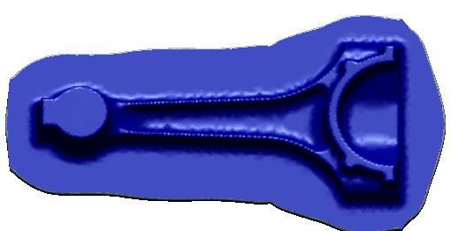
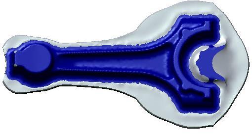
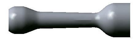
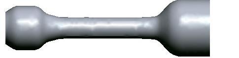
26 Design of the preformed geomerty of a connection rod Calculated geometry forging The sections area A(x) is calculated along the workpiece s axis (x) The stepwise changes are smoothed corrected geometry. Corrected geometry Cross section area diagram A x L V0 A( x) dx 0 2 x d 4 This geometry does not include the material which will go to flash, burn and the wasted at parting.

27 Virtual manufacturing - FEM Cooling of the part during transport

28 Virtual manufacturing - FEM Forming step 1 - Chamfer

29 Virtual manufacturing - FEM Forming step 2 - Upsetting

30 Virtual manufacturing - FEM Forming step 3 Forging

31 Virtual manufacturing - FEM Forming step 3 Forging
32 FEM calculation Original Optimized preforming
33 Design of flash land and gutter kovácsdarab forging Upper die felső sűllyesztékfél sorjahíd Land sorjazseb Gutter Land and gutter geometry is designed, A s is calculated, assumed that is filled up to 70%. d 0.7A d S alsó sűllyesztékfél Lower die The Δd diameter increment must be added to every diameter on the cross section area diagram Common problem that the material does not fill the cavity properly. The volume of the part must be increased: the increased amount of material flowed into flash forces the rest to fill the cavity. In extreme cases up to 50% of the volume can go into flash. It can be reduced by increasing of the number of preforming steps if possible.


34 Design of flash land and gutter Impact surface Machanical presses Open design Screw presses, hammers Closed design
35 Design of preformed geomerty The volume is calculated, which includes the flash. The wasted material by parting and burning must be added. The volume divergence of shearing is ~ 3-4%. It can be increase by using modern processes (e.g band saw). Much more materials can bye wasted by oxidation. In gas-fired furnaces it can reach 13-14%, while in well controlled induction furnaces can be decreased below 1%. For some materials (e.g. titanium alloys) shielding gas can be applied. Based on volume constancy the cat stock s volume can be calculated. If the larges cross section area of the preformed piece is A pre max the stock s cross section A stock must be equal or somewhat larger than A pre max A stock (1...1,05) A premax
36 Design of preforming die The cross section of the billets is usually rectangular for steels, ands circular for light and heavy metals. (steel billet are made rolling, heavy and light metals by extrusion). For light and heavy metals cast ingots are also used. The preformed part is forged directly form the cut stock or after forming with roll forging. The cavity is designed based on the finiching die s geometry. 3 principles: 1) volume constancy 2) correction of the shape 3) altering the grain flow disks: upsetting non-straight long parts: bending The cavity must be fillet without flash land and gutter: the radii and draft angles are higher that in the finishing cavity.
37 Design of preforming die Preforming die Finishing die
38 Design of finishing die The finishing die s cavity is the negative of the forging. The cavity s geometry and the workpieces geometry at room temperature are different. Their geometry is the same only at the final moment of finishing. Workpiece: low alloyed steel, T= C Tools: high alloyed steel, T= C Their temperature and thermal expansion coeffisinets are different. L m0 : workpiece s dimension at T0 L m : workpiece s dimension at forgin temperature S m0 : tool s dimension at T0 S m : tool s dimension at forging temperature α m, α s thermal expansion coefficients of workpiece and the tool the final moment of finishing: L m =L s while the workpiece has T m and the tool T s temperature. L m L m0 1 m T m T0, Ls Ls0 1 s T s T0 1 m T m T0 Ls0 Lm0 1 T T s s 0 = L m0 ( )
39 Role of the flash An important part of the finishing die s design is the flash land an gutter: flash is not only the excess material. The flash cools faster, so its actual yield stress if higher. Because of the geometric conditions, there is a high resistance against the flow. The amount of flash is limited by the deformation of the die: the pressure on the cavity increases due to the flash and so the mechanic load on the dies. It leads to excessive deformation and wear: after a few produced part the die s geometry steps out of the desired tolerance, and must be replaced (increased costs). Orientation in the trimming tool. Ejection of the forging: the ejectors lift the part by the flash, no mark on the foirging surface.

 overload protected")
 Die without flash")
40 Forging without flash The flash is a wasted material and energy. Under strict conditions, it can be avoided: 1) volume constant parting 2) overload protected forging equipment (hydraulic press not common in closed-die forging) Die without flash Compensating the uncertainty of the volume
41 Design of the die single and multiple dies Single and multiple die Solid die and die with insert Multiple operation in one die

42 Mechanical forging press

 Changable")
43 Dies Dies with guide pillars are applicable on these presses Ejector(s) Changable tool segments

44 Arrangement of preforming and finishing operations on mechanical presses
45 Dies for screw presses The spindel can be loaded only in axial direction. Only one oparation pro press is suggested. The resulting force must be alligned with the spindle s axix The flash gutter is closed.
46 Horizontal forging press Stationary lower die punch workpiece Moving lower die Dies: two lower diees one punch Synchronized motion of dies Two, perpendicular parting line Geomertical limitation: buckling
47 Horizontal forging press Technolgical advantages Parts with more complicated shapes can be forged Better tolerances Less or no flash No draft is necessary on inner surfaces. Outer surface: soma as on mechanical presses Good grain flow Working directly from wire or bar. No separate partig step is necessary. Changable die inserts
48 Forging in 4 steps

49 Spindle Forging of long axisymmatrical parts Rotary swag Solid or hollow parts with high tolerance For woth cold and hot forming Stroke: stroke/minute. Application example: rifled barrels Supporting ring Pressure rollers Thrust elements Swaging dies
50 Rotary forging Rotating workpiece: Stationare workpiece: circular cross section poligonal cross section The strain is low, the deformation takes place mainly on the surface The end of the workpiece after forming:


51 For valve-shaped parts. Electric upsetting Electric heating. strain Heating + upsetting Upsetting/forging
Module 3 Selection of Manufacturing Processes. IIT Bombay
 Module 3 Selection of Manufacturing Processes Lecture 3 Design for Bulk Deformation Processes Instructional objectives By the end of this lecture, the students are expected to learn the working principle
Hot Forming. Kalpakjian
 Hot Forming Kalpakjian Hot Working: Forging Open Die Forging www.smeedwerkunica.nl Paul Berenson, www.paulb.com T.Green, WIT Forging: Heat Loss Metal near die surfaces are coolest, flow less www.freedomalloysusa.com
MANUFACTURING PROCESSES
 1 MANUFACTURING PROCESSES - AMEM 201 Lecture 8: Forming Processes (Rolling, Extrusion, Forging, Drawing) DR. SOTIRIS L. OMIROU Forming Processes - Definition & Types - Forming processes are those in which
Casting. Forming. Sheet metal processing. Powder- and Ceramics Processing. Plastics processing. Cutting. Joining.
 Traditional Manufacturing Processes Casting Forming Sheet metal processing Powder- and Ceramics Processing Plastics processing Cutting Joining Surface treatment FUNDAMENTALS OF METAL FORMING Overview of
Bulk Deformation Processes
 Bulk Deformation Processes Bachelor of Industrial Technology Management with Honours Semester I Session 2013/2014 TOPIC OUTLINE What is Bulk Deformation? Classification of Bulk Deformation Processes Types
Chapter 14: Metal-Forging Processes and Equipments
 Manufacturing Engineering Technology in SI Units, 6 th Edition Chapter 14: Metal-Forging Processes and Equipments Chapter Outline Introduction Open-die Forging Impression-die and Closed-die Forging Various
Unit III. Open Die Forging The work piece is compressed between two flat dies facilitating lateral flow of material without constraint,
 Unit III What is Bulk Deformation? Metal forming operations which cause significant shape change by plastic deformation in metallic parts are referred to bulk deformation processes. In most of the cases
MANUFACTURING TECHNOLOGY
 MANUFACTURING TECHNOLOGY UNIT II Hot & Cold Working - Drawing & Extrusion Drawing Drawing is an operation in which the cross-section of solid rod, wire or tubing is reduced or changed in shape by pulling
Chapter 14 Forging of Metals
 Introduction Chapter 14 Forging of Metals Alexandra Schönning, Ph.D. Mechanical Engineering University of North Florida Figures by Manufacturing Engineering and Technology Kalpakijan and Schmid What is
CHAPTER 14. Forging of Metals
 CHAPTER 14 Forging of Metals 2 3 4 5 6 Forging (a) (b) (a) Schematic illustration of the steps involved in forging a bevel gear with a shaft. Source: Forging Industry Association. (b) Landing-gear components
Chapter 16 Bulk Forming Processes. Materials Processing. Types of Deformation (Chapter 16) MET Manufacturing Processes
 MET Manufacturing Processes") MET 33800 Manufacturing Processes Chapter 16 Bulk Forming Processes Before you begin: Turn on the sound on your computer. There is audio to accompany this presentation. Materials Processing Chapters 11-13
MET 33800 Manufacturing Processes Chapter 16 Bulk Forming Processes Before you begin: Turn on the sound on your computer. There is audio to accompany this presentation. Materials Processing Chapters 11-13
CHAPTER 14. Forging of Metals. Kalpakjian Schmid Manufacturing Engineering and Technology Prentice-Hall Page 14-1
 CHAPTER 14 Forging of Metals 2001 Prentice-Hall Page 14-1 Forging (a) (b) Figure 14.1 (a) Schematic illustration of the steps involved in forging a bevel gear with a shaft. Source: Forging Industry Association.
Forging die design and Forging defects
 Forging die design and Forging defects 1.1 Forging die-design aspects: Die design is more empirical and requires experience. Design of die depends on the processing steps, nature of work piece material,
Metal Forming Process. Prof.A.Chandrashekhar
 Metal Forming Process Prof.A.Chandrashekhar Introduction Shaping of a component by the application of external forces is known as the metal forming. Metal forming can be described as a process in which
ME 4563 ME 4563 ME Introduction to Manufacturing Processes. College of Engineering Arkansas State University.
 Introduction to Manufacturing Processes College of Engineering Arkansas State University 1 Bulk Deformation 2 1 Rolling 3 What is Rolling? A process of reducing the thickness (or changing the cross-section
Forging. Types of forging process. 1. Open Die Forgings or Hand forgings. Lecture Notes on Manufacturing Process
 Forging Forging is manufacturing process where metal is pressed, pounded or squeezed under great pressure into high strength parts known as forgings. Heated metal to be shaped is placed on a mold. Pressure
A wide range of cold-formable steel grades and aluminium alloys are used as wire materials within a diameter range from 5 mm to 34 mm.
 Cold-Formed Parts 2 ESKA manufactures complex precision cold-formed parts for applications with large and medium quantities. The highly-efficient cold- forming process ensures economic manufacture of near-net-shape
Introduction. 1. Outline of fan case ring
 A near-net-shape (NNS) ring-rolling process was developed to reduce the forging weight of a rolled, fan case front, ring made of Ti-6Al-4V. This was achieved by optimizing the ring-rolling process in which
Bulk Forming Processes
 Bulk Forming Processes Chapter 16 16.1 Introduction Metal has been shaped by deformation processes for several thousand years Forging, rolling, and wire drawing were performed in the Middle Ages The Industrial
MSE-226 Engineering Materials
 MSE-226 Engineering Materials Lecture-7 ALLOY STEELS Tool Steels TYPES of FERROUS ALLOYS FERROUS ALLOYS Plain Carbon Steels Alloy Steels Cast Irons - Low carbon Steel - Medium carbon steel - High carbon
Chapter 15 Extrusion and Drawing of Metals
 Introduction Chapter 15 Extrusion and Drawing of Metals Alexandra Schönning, Ph.D. Mechanical Engineering University of North Florida Figures by Manufacturing Engineering and Technology Kalpakijan and
2
 1 2 3 4 5 6 7 Direct -Straightforward steady forward force by hydraulic ram Indirect -Has the advantage that there is no friction between billet and chamber (no movement) -Note dummy block at face of ram
QForm. Form3D. Advanced software for forging simulation
 QForm Form3D Advanced software for forging simulation The goals of forging technology : Make the parts of the required shape Provide required properties Do it in time and at the lowest cost Forging process
Bulk Deformation Forming - Rolling
 1 Bulk Deformation Forming - Rolling Overview - Shaping and Forming Powders Pressing SLS Special Injection Molding Firing/ Sintering 2 Raw Material Molten Material Continuous Casting/Rolling Ingot casting
Quality of Simulation Packages for Flashless Hot Forging Operations
 363 Simulation of Materials Processing: Theory, Methods and Applications, Mori (ed.) 2001 Swets & Zeitlinger; Lisse, ISBN 90 2651 822 6 Quality of Simulation Packages for Flashless Hot Forging Operations
Design for Forging. Forging processes. Typical characteristics and applications
 Design for Forging Forging processes Forging is a controlled plastic deformation process in which the work material is compressed between two dies using either impact or gradual pressure to form the part.
COMPUTER SIMULATION BASED DESIGN AND OPTIMISATION OF DIE FORGING OPERATIONS
 COMPUTER SIMULATION BASED DESIGN AND OPTIMISATION OF DIE FORGING OPERATIONS Dr.S.Shamasundar ProSIM, 21/B. 9 th main Shankara Nagara, Mahalakshmipuram Bangalore-560096 Email: shama@pro-sim.com Web: www.pro-sim.com
Lecture 7. Chapter 13. Rolling of Metals. The process of reducing thickness of changing the cross-section 90% of all metals produced by metalworking
 Lecture 7 Chapter 13 Rolling Rolling of Metals The process of reducing thickness of changing the cross-section 90% of all metals produced by metalworking Changes microstructure Larger grains small grains
True Stress and True Strain
 True Stress and True Strain For engineering stress ( ) and engineering strain ( ), the original (gauge) dimensions of specimen are employed. However, length and cross-sectional area change in plastic region.
NUMERICAL AND EXPERIMENTAL INVESTIGATION OF FORGING PROCESS OF A CV JOINT OUTER RACE
 NUMERICAL AND EXPERIMENTAL INVESTIGATION OF FORGING PROCESS OF A CV JOINT OUTER RACE 1 M.M. MOHAMMADI and 2 M.H.SADEGHI. 1 CAD/CAM Laboratory, Manufacturing Engineering Division, School of Engineering,
Bulk Deformation Rolling Processes Forging Processes Extrusion Processes Wire and Bar Drawing Sheet Metal Forming Bending Operations Deep or Cup
 Metal Forming Bulk Deformation Rolling Processes Forging Processes Extrusion Processes Wire and Bar Drawing Sheet Metal Forming Bending Operations Deep or Cup Drawing Shearing Processes Miscellaneous Processes
Questions concerning the contents of the lecture Manufacturing Technology
 Questions concerning the contents of the lecture Manufacturing Manufaturing I 1. Introduction to Manufacturing No related questions 2. Measuring and Testing in Production 1. Explain systematic errors and
Metal extrusion. Metal stamping
 Metal extrusion Answer the following questions 1. In which of the following extrusion operation is friction a factor in determining the extrusion force (one best answer): (a) direct extrusion or (b) indirect
Mechanical behavior of crystalline materials- Comprehensive Behaviour
 Mechanical behavior of crystalline materials- Comprehensive Behaviour In the previous lecture we have considered the behavior of engineering materials under uniaxial tensile loading. In this lecture we
3. Residual Stresses
 3. Residual Stresses 3. Residual Stresses 22 Figure 3.1 br-ei-3-1e.cdr weld Various Reasons of Residual Stress Development grinding disk less residual stresses, and it will never be stress-free! The emergence
SHRI GURU GOBIND SINGHJI INSTITUTE OF ENGG & TECHNOLOGY DEPARTMENT OF PRODUCTION ENGINEERING SUBJECT:MECHANICAL WORKING OF METALS EXPERIMENT NO: 3
 SHRI GURU GOBIND SINGHJI INSTITUTE OF ENGG & TECHNOLOGY DEPARTMENT OF PRODUCTION ENGINEERING SUBJECT:MECHANICAL WORKING OF METALS EXPERIMENT NO: 3 AIM: STUDY OF FORGING EQUIPMENT AIM: Study of forging
where n is known as strain hardening exponent.
 5.1 Flow stress: Flow stress is the stress required to sustain a certain plastic strain on the material. Flow stress can be determined form simple uniaxial tensile test, homogeneous compression test, plane
Material flow analysis for hot-forming of 20MnCr5 gear wheel blanks
 IDE 2008, Bremen, Germany, September 17 th 19 th, 2008 77 Material flow analysis for hot-forming of 20MnCr5 gear wheel blanks Rüdiger Rentsch Foundation Institute of Materials Science (IWT), Badgasteinerstr.
Powder-Metal Processing and Equipment
 Powder-Metal Processing and Equipment Text Reference: Manufacturing Engineering and Technology, Kalpakjian & Schmid, 6/e, 2010 Chapter 17 Powder Metallurgy Metal powders are compacted into desired and
PLATE FORGING FOR CONTROLLING WALL THICKNESS DISTRIBUTION OF PRODUCTS
 PLATE FORGING FOR CONTROLLING WALL THICKNESS DISTRIBUTION OF PRODUCTS Ken-ichiro Mori Department of Mechanical Engineering, Toyohashi University of Technology, Japan Summary Plate forging processes for
Manufacturing Process II. Forging
 Manufacturing Process II Forging Introduction Forging is a deformation process in which the work is compressed between two dies, using either impact or gradual pressure to form the part. It is the oldest
Powder Metallurgy. Powder-Metal Processing and Equipment 11/10/2009
 Powder Metallurgy Powder-Metal Processing and Equipment Metal powders are compacted into desired and often complex shapes and sintered* to form a solid piece * Sinter: To heat without melting Text Reference:
Extrusion of complex shapes
 Extrusion of complex shapes 1 Hot extrusion Hot extrusion is the process of forcing a heated billet to flow through a shaped die opening It is used to produce long, strait metal products of constant cross
Hull and machinery steel forgings
 (1978) (Rev.1 1980) (Rev.2 July 2002) (Rev.3 May 2004) Hull and machinery steel forgings.1 Scope.1.1 These requirements are applicable to steel forgings intended for hull and machinery applications such
Research on the Near-net Forging Processes for the Shell Body Made by High-strength Steel Taibin Wu1, a, b
 International Conference on Mechanics, Materials and Structural Engineering (ICMMSE 2016) Research on the Near-net Forging Processes for the Shell Body Made by High-strength Steel Taibin Wu1, a, b 1 Research
VDM Alloy 80 A Nicrofer 7520 Ti
 VDM Alloy 80 A Nicrofer 7520 Ti Material Data Sheet No. 4048 February 2017 February 2017 VDM Alloy 80 A 2 VDM Alloy 80 A Nicrofer 7520 Ti VDM Alloy 80 A is a nickel-chromium alloy that can be age-hardened.
Heinz Tschaetsch Metal Forming Practise
 Heinz Tschaetsch Metal Forming Practise Heinz Tschaetsch Metal Forming Practise Processes Machines Tools Translated by Anne Koth 123 Author: Professor Dr.-Ing. e. h. Heinz Tschaetsch Paul-Gerhardt-Str.
Resource Guide. Section 3: Ductile Iron
 Resource Guide Section 3: Ductile Iron Section 3 Ductile Iron Description of Grades... 3-3 65-45-12 Ferritic... 3-4 80-55-06 Partially Pearlitic... 3-6 100-70-02 Pearlitic... 3-8 4512 HRDS Heat Resistant...
FRAUNHOFER INSTITUTE FOR MACHINE TOOLS AND FORMING TECHNOLOGY IWU SIMULATION IN FORMING TECHNOLOGY
 FRAUNHOFER INSTITUTE FOR MACHINE TOOLS AND FORMING TECHNOLOGY IWU SIMULATION IN FORMING TECHNOLOGY 1 SIMULATION IN SHEET METAL FORMING Simulation is an essential part of the development chain, especially
COLD FORGING OF STEEL. H. D. Feldmann, Technical Director, Cold Forging Ltd. Hutchinson Scientific & Technical, London, 1959.
 COLD FORGING OF STEEL H. D. Feldmann, Technical Director, Cold Forging Ltd. Hutchinson Scientific & Technical, London, 1959 Contents Preface 7 I Introduction 15 A Terminology 15 B Purpose of this book
Chapter 11: Applications and Processing of Metal Alloys
 Chapter 11: Applications and Processing of Metal Alloys ISSUES TO ADDRESS... What are some of the common fabrication techniques for metals? What heat treatment procedures are used to improve the mechanical
Chapter 15 Fundamentals of Metal Forming. Materials Processing. Deformation Processes. MET Manufacturing Processes
 MET 33800 Manufacturing Processes Chapter 15 Fundamentals of Metal Forming Before you begin: Turn on the sound on your computer. There is audio to accompany this presentation. Materials Processing Chapters
Objectives. This chapter provides fundamental background on processes of drawing of rods, wires and tubes.
 WIRE DRAWING Objectives This chapter provides fundamental background on processes of drawing of rods, wires and tubes. Mathematical approaches for the calculation of drawing load will be introduced. Finally
CAE Analysis of Crankshaft for Testing Dynamic Loads for Reducing Cost & Weight
 2303-2307 CAE Analysis of Crankshaft for Testing Dynamic Loads for Reducing Cost & Weight Salim Ahmed, Tasmeem Ahmad Khan Abstract This study was conducted on a single cylinder four stroke cycle engine.
1. METALS 2. FERRIC METALS 3. NON-FERRIC METALS 4. WORKING WITH METALS 5. METAL FORMING TECHNIQUES 6. ENVIRONMENTAL IMPACT OF METAL EXTRACTION
 METALS: 1. METALS 2. FERRIC METALS 3. NON-FERRIC METALS 4. WORKING WITH METALS 5. METAL FORMING TECHNIQUES 6. ENVIRONMENTAL IMPACT OF METAL EXTRACTION 1. METALS: Metals are chemical elements found in nature
Types of manufacturing processes
 Materials processing Metal parts undergo sequence of processes Primary alter the ( raw ) material s basic shape or form. Sand casting Rolling Forging Sheet metalworking Types of manufacturing processes
Comparison of BS and BS EN for steel materials
 Comparison of BS and BS EN for steel materials Appendix This table only highlights the comparison of BS and BS EN on steel materials, which are relevant to plan approval. Title of BS BS BS EN Title of
Design and Analysis of a Forging Die for Manufacturing of Multiple Connecting Rods
 IOP Conference Series: Materials Science and Engineering PAPER OPEN ACCESS Design and Analysis of a Forging Die for Manufacturing of Multiple Connecting Rods To cite this article: C E Megharaj et al 2016
The Convenience Stores For Metal
 TOOL STEEL SELECTOR GUIDE Application Suggested Grades Arbors... O1, A2, A6 Battering Tools... S5, S1, S7 Blacksmith Tools... S5, S1 Boiler-Shop Tools... S5, S1, S7 Bolt Clippers... S5, S1 Boring Tools...
Licensed Copy: John May, Powertrain Ltd., February 20, 2002, Uncontrolled Copy, (c) BSI
 BSI") BRITISH STANDARD BS 70-3: Incorporating Amendment Nos. 1 and 2 Specification for Wrought steel for mechanical and allied engineering purposes Part 3: Bright bars for general engineering purposes BS70-3:
BRITISH STANDARD BS 70-3: Incorporating Amendment Nos. 1 and 2 Specification for Wrought steel for mechanical and allied engineering purposes Part 3: Bright bars for general engineering purposes BS70-3:
STEELS & COATINGS FOR CUTTING TOOL APPLICATIONS
 STEELS & COATINGS FOR CUTTING TOOL APPLICATIONS Requirements for cutting tools There are several characteristics that are essential to the good performance of a cutting tool. Powder Metal High Speed Steels
Technologies for Process Design of Titanium Alloy Forging for Aircraft Parts
 Technologies for Process Design of Titanium Alloy Forging for Aircraft Parts Takashi CHODA *1, Dr. Hideto OYAMA *2, Shogo MURAKAMI *3 *1 Titanium Research & Development Section, Titanium Div., Iron & Steel
Uddeholm Formvar. FORMVAR is a trade mark registered in the European Union
 Uddeholm Formvar FORMVAR is a trade mark registered in the European Union UDDEHOLMS AB No part of this publication may be reproduced or transmitted for commercial purposes without permission of the copyright
Cork Institute of Technology. Autumn 2005 Manufacturing Engineering (Time: 3 Hours)
") Cork Institute of Technology Bachelor of Engineering (Honours) in Mechanical Engineering Stage 3 (Bachelor of Engineering in Mechanical Engineering Stage 3) Instructions Answer FIVE questions. Answer TWO
Cork Institute of Technology Bachelor of Engineering (Honours) in Mechanical Engineering Stage 3 (Bachelor of Engineering in Mechanical Engineering Stage 3) Instructions Answer FIVE questions. Answer TWO
Forging. Types of Forging Dies. Open-Die Forging. Outline. Forging. Types of forging Forging analysis Examples
 Forging Outline Forging Types of forging Forging analysis Examples Oldest of te metal forming operations, dating from about 5000 B C Components: engine cranksafts, connecting rods, gears, aircraft structural
5 PRODUCTION COST ESTIMATION. PRODUCTION COST ESTIMATION : Instructional Objectives
 Production Cost Estimation 129 5 PRODUCTION COST ESTIMATION PRODUCTION COST ESTIMATION : Instructional Objectives After studying this unit, the student should be able to : (i) Know how cost costimation
Selection of Tool & Die Steels
 Selection of Tool & Die Steels Introduction The success of a metal forming tool depends on optimizing all the factors affecting its performance. Usually, operating conditions (applied loads, abrasive environments,
TMK HYDRA ART INSIDE SKIVED AND ROLLER BURNISHED COLD FINISHED SEAMLESS STEEL TUBES and PISTON RODS TUBES FOR HYDRAULIC CYLINDERS
 TMK HYDRA ART INSIDE SKIVED AND ROLLER BURNISHED COLD FINISHED SEAMLESS STEEL TUBES and PISTON RODS TUBES FOR HYDRAULIC CYLINDERS TMK is one of the world s leading producers of tubular products for the
Characteristics of Forging
 Forging of Metals Forged Components Figure 14.1 (a) Schematic illustration of the steps involved in forging a knife. (b) Landinggear components for the C5A and C5B transport aircraft, made by forging.
The entire world of forging
 The entire world of forging Forming the Future Put it into motion. Forging with Schuler. For over 150 years, the name Schuler has been synonymous with innovative technologies, quality and customer-oriented
CLAD STAINLESS STEELS AND HIGH-NI-ALLOYS FOR WELDED TUBE APPLICATION
 CLAD STAINLESS STEELS AND HIGHNIALLOYS FOR WELDED TUBE APPLICATION Wolfgang Bretz Wickeder Westfalenstahl GmbH Hauptstrasse 6 D58739 Wickede, Germany Keywords: Cladding, Laser/TIG Welding, Combined SolderingWelding
Anchor chain cables and accessories
 CLASS PROGRAMME Approval of manufacturers DNVGL-CP-0254 Edition May 2016 The content of this service document is the subject of intellectual property rights reserved by ("DNV GL"). The user accepts that
INDEX. forging Axisymmetric isothermal forging, cabbaging, compression of cylinders,
 INDEX Accuracy of simulation, 333 Air bending, 21, 141-147 Air rounding, 21 ALPID program, 136 Analysis in metal forming, 26-52 closed-die forging, 34, 35-36, 37 cold extrusion, 39-41 cold forging, 39-41
MECHANICS OF MATERIALS
 Lecture Notes: Dr. Hussam A. Mohammed Al- Mussiab Technical College Ferdinand P. Beer, E. Russell Johnston, Jr., and John T. DeWolf Introduction Concept of Stress The main objective of the study of mechanics
AISI A2 Cold work tool steel
 T OOL STEEL FACTS AISI A2 Cold work tool steel Great Tooling Starts Here! General AISI A2 is an air- or oil hardening chromiummolybdenum-vanadium alloyed tool steel characterized by: Good machinability
AISI D2 Cold work tool steel
 T OOL STEEL FACTS AISI D2 Cold work tool steel Great Tooling Starts Here! This information is based on our present state of knowledge and is intended to provide general notes on our products and their
Mechanical behavior of crystalline materials - Stress Types and Tensile Behaviour
 Mechanical behavior of crystalline materials - Stress Types and Tensile Behaviour 3.1 Introduction Engineering materials are often found to posses good mechanical properties so then they are suitable for
LOAD BEARING ROLLER ASSEMBLIES Engineering Data Installation Notes
 Installation Notes INSTALLING STUD TYPE LOAD BEARING ROLLER ASSEMBLIES Mounting holes should be machined to the nominal stud size within +.001/-.000 (+.025mm / -.000mm) tolerance. When properly aligned,
Stainless Steel & Stainless Steel Fasteners Chemical, Physical and Mechanical Properties
 Stainless Steel & Stainless Steel Fasteners Chemical, Physical and Mechanical Properties Stainless steel describes a family of steels highly resistant to tarnishing and rusting that contain at least two
Numerical investigation of manufacturing hollow preforms by combining the processes backward cup extrusion and piercing
 MATEC Web of Conferences 80, Numerical investigation of manufacturing hollow preforms by combining the processes backward cup extrusion and piercing Robinson Henry 1,a and Mathias Liewald 1 1 Institute
Cast Steel Propellers W27. (May 2000) (Rev.1 May 2004)
 (Rev.1 May 2004)") (May 2000) (Rev.1 May 2004) Cast Steel Propellers 1. Scope 1.1 These unified requirements are applicable to the manufacture of cast steel propellers, blades and bosses. 1.2 Where the use of alternative
(May 2000) (Rev.1 May 2004) Cast Steel Propellers 1. Scope 1.1 These unified requirements are applicable to the manufacture of cast steel propellers, blades and bosses. 1.2 Where the use of alternative
ERC/NSM Activities. Research for Industry and Government
 / Activities Research for Industry and Government Stamping Hydroforming Machining Forging / Activities in Tube Hydroforming 1. Materials Determination of material flow stress data for tubular materials
AEROSPACE MATERIAL SPECIFICATION
 AEROSPACE MATERIAL SPECIFICATION AMS 6414K Issued JAN 1964 Revised FEB 2007 Superseding AMS 6414J Steel, Bars, Forgings, and Tubing 0.80Cr - 1.8Ni - 0.25Mo (0.38-0.43C) (SAE 4340) Vacuum Consumable Electrode
special hot work tool steel CR7V-L
 special hot work tool steel CR7V-L T h e p r e m i u m s t e e l w i t h m a x i m u m h i g h t e m p e r at u r e w e a r r e s i s ta n c e 2 From the casting of steel to finished die... LONG-STANDING
ISO INTERNATIONAL STANDARD
 - INTERNATIONAL STANDARD ISO 9327-1 First edition 1999-04-15 Steel forgings and rolled or forged bars for pressure purposes Technical delivery conditions Part 1: General requirements Pièces forgées et
MACHINES DESIGN SSC-JE STAFF SELECTION COMMISSION MECHANICAL ENGINEERING STUDY MATERIAL MACHINES DESIGN
 1 SSC-JE STAFF SELECTION COMMISSION MECHANICAL ENGINEERING STUDY MATERIAL C O N T E N T 2 1. MACHINE DESIGN 03-21 2. FLEXIBLE MECHANICAL ELEMENTS. 22-34 3. JOURNAL BEARINGS... 35-65 4. CLUTCH AND BRAKES.
EXPERIMENTAL EVALUATION OF RBD PALM OLEIN AS LUBRICANT IN COLD METAL FORMING
 Jurnal Mekanikal December 2010, No. 31, 1-10 EXPERIMENTAL EVALUATION OF RBD PALM OLEIN AS LUBRICANT IN COLD METAL FORMING S. Syahrullail *1, S. Kamitani 2 and K. Nakanishi 2 1 Faculty of Mechanical Engineering,
Properties in Shear. Figure 7c. Figure 7b. Figure 7a
 Properties in Shear Shear stress plays important role in failure of ductile materials as they resist to normal stress by undergoing large plastic deformations, but actually fail by rupturing under shear
1. 3 Extrusion molding
 1. 3 Extrusion molding 9 Extrusion is a widely used technique, both in the field of traditional and technical ceramics. This method allows the continuous manufacture of products with a constant cross-
STRENGTH OF MATERIALS laboratory manual
 STRENGTH OF MATERIALS laboratory manual By Prof. Shaikh Ibrahim Ismail M.H. Saboo Siddik College of Engineering, MUMBAI TABLE OF CONTENT Sr. No. Title of Experiment page no. 1. Study of Universal Testing
Steel Forgings: Design, Production, Selection, Testing, and Application. Edward G. Nisbett. ASTM Stock No. MNL53
 Steel Forgings: Design, Production, Selection, Testing, and Application Edward G. Nisbett ASTM Stock No. MNL53 INTERNATIONAL Standards Worldwide ASTM International 100 Barr Harbor Drive PO Box C700 West
Viking Forge Corp. If you want to be sure FORGE IT!!!
 Viking Forge Corp. If you want to be sure FORGE IT!!! Viking Forge An ISO 9001:2000 Company Offices: 4,000 Square Feet Tool & Die Shop: 12,000 Square Feet Forging Operations: 78,000 Square Feet 20 Acres
HOW TO BUY FORGINGS. The Design Conference
 HOW TO BUY FORGINGS Close cooperation between buyers and producers of forgings has always been a vital part of achieving the best possible product at the lowest possible cost. With major advances in forging
Types of Strain. Engineering Strain: e = l l o. Shear Strain: γ = a b
 Types of Strain l a g Engineering Strain: l o l o l b e = l l o l o (a) (b) (c) Shear Strain: FIGURE 2.1 Types of strain. (a) Tensile. (b) Compressive. (c) Shear. All deformation processes in manufacturing
HOT ROLLED STEEL FLAT PRODUCTS FOR STRUCTURAL FORMING AND FLANGING PURPOSES SPECIFICATION (Third Revision of IS 5986)
") For Comments Only Draft Indian Standard Doc: MTD 4(4939) HOT ROLLED STEEL FLAT PRODUCTS FOR STRUCTURAL FORMING AND FLANGING PURPOSES SPECIFICATION (Third Revision of IS 5986) ICS 77.140.50 Not to be reproduced
For Comments Only Draft Indian Standard Doc: MTD 4(4939) HOT ROLLED STEEL FLAT PRODUCTS FOR STRUCTURAL FORMING AND FLANGING PURPOSES SPECIFICATION (Third Revision of IS 5986) ICS 77.140.50 Not to be reproduced
Phase diagrams CCT and CCCT; Transformation kinetics. Flow curves with realistic deformation conditions. (temperature, strain rate and strain)
") Prace IMZ 1 Dodatek (2012) Semi-industrial scale simulation of processes... 47 48 Rudolf Kawalla, Gerd Goldhahn, Grzegorz Korpala Prace IMZ 1 Dodatek (2012) Test and Pilot Facilities Order administration
Prace IMZ 1 Dodatek (2012) Semi-industrial scale simulation of processes... 47 48 Rudolf Kawalla, Gerd Goldhahn, Grzegorz Korpala Prace IMZ 1 Dodatek (2012) Test and Pilot Facilities Order administration
Fundamentals for Steel Constructions
 Fundamentals for Steel Constructions 1. General design principles applicable to welded constructions 2. Frames, girders, etc. 3. Sheet metal construction, box girder 4. Drafting 5. Common welds at Broetje-Automation
AEROSPACE MATERIAL SPECIFICATION
 AEROSPACE MATERIAL SPECIFICATION Licensed to Juan Rodriguez AMS 5754M Issued MAY 1954 Revised AUG 2007 Superseding AMS 5754L Nickel Alloy, Corrosion and Heat-Resistant, Bars, Forgings, and Rings 47.5Ni
ANSWER ONLY FIVE QUESTIONS
 Ministry of Higher Education & Scientific Research, Baghdad-Iraq University Of Technology Department of Materials Engineering وزارة التعليم العالي والبحث العلمي بغاد - العراق الجامعت التكنولوجيت قسم هندست