REPORT OF SUBSURFACE INVESTIGATION AND GEOTECHNICAL ENGINEERING SERVICES. Proposed Soundside Boardwalk Expansion Duck, North Carolina
|
|
|
- Austen Wheeler
- 6 years ago
- Views:
Transcription

1 REPORT OF SUBSURFACE INVESTIGATION AND GEOTECHNICAL ENGINEERING SERVICES Proposed Soundside Boardwalk Expansion Duck, North Carolina G E T PROJECT NO: EC10-260G November 17, 2010 Prepared for VHB, Inc Greenwich Rd. Suite 302 Virginia Beach, VA ATTN: MR. Chris DeWitt, AICP Prepared by GET Solutions, Inc. 106 Capital Trace Unit E, Elizabeth City, NC

2 November 17, 2010 TO: VHB, Inc Greenwich Rd. Suite 302 Virginia Beach, VA Attn: Mr. Chris DeWitt, AICP RE: Report of Subsurface Investigation and Geotechnical Engineering Proposed Soundside Boardwalk Expansion Duck, North Carolina GET Project No: EC10-260G Dear Mr. DeWitt: In compliance with your instructions, we have completed our Subsurface Investigation and Geotechnical Engineering Services for the above referenced project. The results of this study, together with our recommendations, are presented in this report. Often, because of design and construction details that occur on a project, questions arise concerning subsurface conditions. G E T Solutions, Inc. would be pleased to continue its role as Geotechnical Engineer during the project implementation. Thank you for the opportunity to work with you on this project. We trust that the information contained herein meets your immediate need, and should you have any questions or if we could be of further assistance, please do not hesitate to contact us. Respectfully Submitted, G E T Solutions, Inc. Gerald W. Stalls Jr., P.E. Senior Project Engineer NC Reg. # Camille A. Kattan, P.E. Principal Engineer NC Reg. # Copies: (1) Client 106 Capital Trace Unit E Elizabeth City, NC Phone: (252) Fax: (252) info@getsolutionsinc.com
3 Report of Subsurface Investigation and Geotechnical Engineering Services November 17, 2010 Proposed Soundside Boardwalk Expansion Duck, North Carolina GET Project No: EC10-260G EXECUTIVE SUMMARY The project site is located along the east shoreline of the Currituck Sound in the Town of Duck, North Carolina. The construction at the site is planned to consist of building a new expansion of the existing boardwalk. The boardwalk is to consist of wood frame construction with a width of about 10 feet and a finished deck elevation of about 7 feet MSL. The proposed boardwalk is to be supported by round timber piles driven to depths ranging from 15 to 20 feet below the varying existing site grade elevations in order to develop the allowable compression capacity of about 15 tons. Our field exploration program included six (6) 25-foot deep SPT borings, four (4) 3- to 7- foot deep hand auger borings with Dynamic Cone Penetrometer (DCP) tests, and four (4) 5-foot deep DCP tests performed by G E T Solutions, Inc. along the alignment of the proposed boardwalk expansions. A brief description of the natural subsurface soil conditions is tabulated on the following page: AVERAGE DEPTH (Feet) STRATUM DESCRIPTION RANGES OF SPT (1) N- VALUES Borings: B-1 through B-6 and HA-1 through HA-4 0 to TOPSOIL and/or PEAT (PT) to 3 25 (2) I SAND (SP, SP-SM, SM) with varying amounts of silt 2 to to to 3.5 to 4 IA IB SAND (SP-SM, SM) with varying amounts of organics and/or PEAT; Borings B-1, B-5, B-6, HA-2, and HA-4 Silty Fibrous PEAT (PT) with varying amounts of sand; Borings B-3, HA-1 1 to 7 2 to 3 Note (1) SPT = Standard Penetration Test, N-Values in Blows-per-foot. Note (2): These depths represent the boring termination depths ranging from 3 to 25 feet below the existing site grade elevations at the relevant boring locations. The groundwater level encountered at the location of borings B-1 through B-6 and HA-1 through HA-4 was observed through the wetness of the recovered soil samples during the drilling operations. The initial groundwater table was measured to occur at depths ranging from 1.5 to 5 feet below current grades at the boring locations. The observed groundwater levels were noted to correspond to elevations generally ranging from about 0.5 to 1.5 feet (MSL). The varying groundwater levels are anticipated to be effected by the existing topography of the project site. The boreholes were backfilled upon completion for safety considerations. As such, the reported groundwater levels may not be indicative of the static groundwater level. i
4 Report of Subsurface Investigation and Geotechnical Engineering Services November 17, 2010 Proposed Soundside Boardwalk Expansion Duck, North Carolina GET Project No: EC10-260G The following preliminary evaluations and recommendations were developed based on our field exploration and laboratory-testing program: Field testing program during construction to include test and production pile testing and monitoring, and/or vibration monitoring. All other applicable testing, inspections, and evaluations should be performed as indicated in the North Carolina State Building Code (2009 International Building Code with North Carolina Amendments). It is anticipated that deep foundations comprised of round timber piles (with a minimum tip diameter of 8-inches) driven to pile tip elevations ranging from about -10 feet to -17 feet MSL will develop allowable compression capacities on the order of about 10 tons, respectively. The pile foundations should be installed and tested to ultimate capacities (2.25 times the allowable capacities) to account for negative skin friction loads. It is anticipated that the total butt settlements (including elastic shortening) will not exceed about ½-inch, which is the settlement necessary to mobilize the soil/pile capacity in combination with the pile tip settlements due to the stress increase in the underlying soils. It is recommended that a test pile program be implemented in order to establish the criteria for pile installation including the development of final tip elevations and to confirm that the contractor s equipment and installation methods are acceptable. Once the test pile program has been successfully completed, the geotechnical engineer should observe all production piles to verify that their installation is being performed in accordance with the previously derived pile driving criteria. Proposed structures should be designed based on a site seismic classification of D, based on the results of the 25-foot deep SPT borings performed at this site, our experience in the project area, and the requirements provided in provided in the North Carolina State Building Code (2009 International Building Code with North Carolina Amendments). This summary briefly discusses some of the major topics mentioned in the attached report. Accordingly, this report should be read in its entirety to thoroughly evaluate the contents. ii
5 TABLE OF CONTENTS page 1 of 1 EXECUTIVE SUMMARY...i 1.0 PROJECT INFORMATION Project Authorization Project Description Purpose and Scope of Services FIELD AND LABORATORY PROCEDURES Field Exploration Laboratory Testing SITE AND SUBSURFACE CONDITIONS Site Location and Description Subsurface Soil Conditions Groundwater Information EVALUATION AND RECOMMENDATIONS Clearing and Grading Pile Settlement - Preliminary Timber Piles Pile Installation Monitoring Pre-Augered or Jetted Piles Test Piles Establishing Pile Driving Criteria Driven Piles Pile Installation Monitoring Adjacent Structures Driven Piles Seismic Evaluation CONSTRUCTION CONSIDERATIONS Drainage and Groundwater Concerns Excavations REPORT LIMITATIONS...13 APPENDIX I APPENDIX II APPENDIX III APPENDIX IV BORING LOCATION PLAN BORING LOGS GENERALIZED SOIL PROFILE CLASSIFICATION SYSTEM FOR SOIL EXPLORATION 20
6 Report of Subsurface Investigation and Geotechnical Engineering Services November 17, 2010 Proposed Soundside Boardwalk Expansion Duck, North Carolina GET Project No: EC10-260G 1.1 Project Authorization 1.0 PROJECT INFORMATION G E T Solutions, Inc. has completed our Geotechnical Engineering study for the Phase I and Phase II portions of the proposed Soundside Boardwalk Expansion project. The Geotechnical Engineering Services were conducted in general accordance with G E T Solutions, Inc. Proposal No. PEC10-242G, dated October 15, Authorization to proceed with the services was received in the form of an from Mr. Chris DeWitt with VHB, Inc. on the date of October 26, Project Description This development at this site is to include the construction of an expansion to the existing soundside boardwalk, which is to be performed in two (2) phases. Phase I will extend from the north end of the existing boardwalk to approximately 230 feet north of the southwest retail building in the Wee Winks Square shopping center. Additionally, Phase I will also include replacing the existing pier located north of the Kitty Hawk Kites retail store and an extension of the pier to approximately 340 feet to the north. Phase II will extend from the south end of the existing boardwalk to the existing pier located west of the Wings retail store. The new boardwalk will have an approximate width of 10 feet, a finished deck elevation of 7 feet MSL, and will be constructed of wood framing. The boardwalk will be supported by a deep foundation system comprised of round timber piles driven to a depth of about 15 feet below the existing site grade elevations and/or mud-line elevations. The pile foundation loads associated with the boardwalks were not known at this time. However, based on our experience with the design of the existing bulkhead at this site and other similar projects, the maximum axial pile foundation loads are not expected to exceed about 15 tons in compression. If any of the noted information is incorrect or has changed, please inform G E T Solutions, Inc. so that we may amend the recommendations presented in this report, if appropriate. 1.3 Purpose and Scope of Services The purpose of this study was to obtain information on the general subsurface conditions at the proposed project site. The subsurface conditions encountered were then evaluated with respect to the available project characteristics. In this regard, engineering assessments for the following items were formulated: 1. General assessment of the soils revealed by the borings performed at the proposed development. 1
7 Report of Subsurface Investigation and Geotechnical Engineering Services November 17, 2010 Proposed Soundside Boardwalk Expansion Duck, North Carolina GET Project No: EC10-260G 2. General location and description of potentially deleterious material encountered in the borings that may interfere with construction progress or structure performance, including existing fills or surficial/subsurface organics. 3. Feasibility of utilizing a deep foundation system for support of the proposed boardwalk and bridge. Design parameters required for the foundation systems, including pile embedment depths, allowable pile capacities (compression, tension and lateral), and estimated settlements. 4. Seismic site classification provided based on the results of the 25-foot deep SPT borings performed within the project area. The scope of services did not include an environmental assessment for determining the presence or absence of wetlands or hazardous or toxic material in the soil, bedrock, surface water, groundwater or air, on or below or around this site. Prior to development of this site, an environmental assessment is advisable. 2.1 Field Exploration 2.0 FIELD AND LABORATORY PROCEDURES In order to explore the general subsurface soil types and to aid in developing associated foundation parameters, six (6) 25-foot deep Standard Penetration Test (SPT) borings (designated as B-1 through B-6) were drilled within the proposed structures footprints. Additionally, a total of four (4) 3- to 7-foot deep hand auger borings with Dynamic Cone Penetrometer (DCP) tests (designated as HA-1 through HA-4) and four (4) 5-foot deep DCP tests (designated as DCP-1 through DCP-4) were performed within the proposed boardwalk expansion areas. Boring B-1 was offset approximately 20 feet north due to the presence of existing concrete paving. Due to the financial constraints of the project, our scope of services as it relates to SPT borings was limited to that accessible with the use of a truck rig or a tripod rig. Furthermore, the use of a drill rig or barge suitable to access the portions of the boardwalk extending over open water was requested to not be included in our scope of services. Standard Penetration Tests were performed in the field in general accordance with ASTM D The tests were performed continuously from the existing ground surface to depths of 10 to 12 feet, and at 5-foot intervals thereafter. The soil samples were obtained with a standard 1.4 I.D., 2 O.D., 30 long split-spoon sampler. The sampler was driven with blows of a 140 lb. hammer falling 30 inches. The number of blows required to drive the sampler each 6-inch increment of penetration was recorded and is shown on the boring logs. The sum of the second and third penetration increments is termed the SPT N-value. A representative portion of each disturbed split-spoon sample was collected with each SPT, placed in a glass jar, sealed, labeled, and returned to our laboratory for review. 2
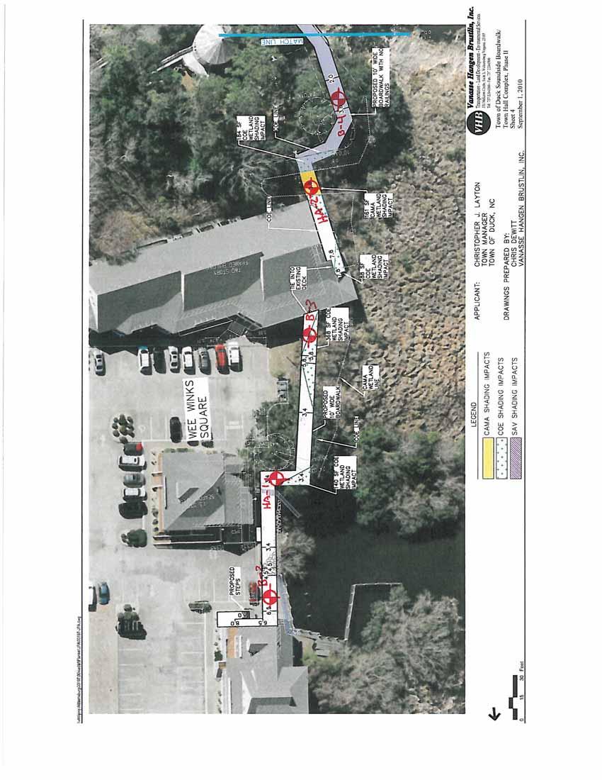
8 Report of Subsurface Investigation and Geotechnical Engineering Services November 17, 2010 Proposed Soundside Boardwalk Expansion Duck, North Carolina GET Project No: EC10-260G The DCP testing procedures performed at the locations designated as DCP-1 through DCP-4 were not performed in strict accordance with ASTM STP 399 as they were performed continuously from the existing mud-line elevations to their termination depths. Furthermore, these DCP tests were performed solely to determine a qualitative evaluation of the shallow sub-aquatic soils. Following the exploration procedures, the borings were backfilled with a neat cement grout mix in accordance with NCDENR requirements. More specific information regarding boring depths and locations is provided in the following table (Table I Boring Schedule). Table I Boring Schedule Boring Number Boring Depth (feet) Exploration Method Boring Location B-1 25 SPT (1) North Expansion; Northeast of Existing Boat Ramp (North of Kitty Hawk Kites) B-2 25 SPT (1) North Expansion; Wee Winks Square; North End B-3 25 SPT (1) North Expansion; Wee Winks Square; South End B-4 25 SPT (1) North Expansion; Approx. 380 feet North of the South End B-5 25 SPT (1) South Expansion; Approx. 80 feet East of the North End B-6 25 SPT (1) South Expansion; Approx. 20 feet North of the South End HA Hand Auger & DCP (2) North Expansion; Wee Winks Square; Approx. Center HA-2 5 Hand Auger & DCP (2) North Expansion; Approx. 420 feet North of the South End HA-3 3 Hand Auger & DCP (2) North Expansion; Approx. 210 feet North of The South End HA-4 7 Hand Auger & DCP (2) South Expansion; Approximate Center DCP-1 5 DCP (2) North Expansion; Approx. North End DCP-2 5 DCP (2) North Expansion; 190 feet South of North End DCP-3 5 DCP (2) North Expansion; Approx. Intersection with Existing Kitty Hawk Kite Pier DCP-4 5 DCP (2) North Expansion; Approx. 150 feet West of the East end of the Existing Kitty Hawk Kite Pier Note (1): SPT = Standard Penetration Test boring. Note (2): DCP = Dynamic Cone Penetrometer probe. The boring locations were established and located in the field by representatives of G E T Solutions, Inc. by measuring from existing site features. The approximate boring locations are shown on the attached Boring Location Plan(s) (Appendix I), which were reproduced based on the site plan provided by the VHB, Inc. 3
9 Report of Subsurface Investigation and Geotechnical Engineering Services November 17, 2010 Proposed Soundside Boardwalk Expansion Duck, North Carolina GET Project No: EC10-260G 2.2 Laboratory Testing Representative portions of all soil samples collected during drilling were sealed in glass jars, labeled and transferred to our laboratory for classification and analysis. The soil classification was performed by a Geotechnical Engineer in accordance with ASTM D2488. A total of three (3) representative soil samples were selected and subjected to laboratory testing, which included natural moisture and -#200 sieve wash testing and analysis, in order to corroborate the visual classification. These test results are provided in the following table (Table II Laboratory Test Results) and are also presented on the Boring Log sheets (Appendix II). Table II - Laboratory Test Results Boring No. Sample Type Depth (Ft) Natural Moisture Content (%) -#200 Sieve (%) Classification (USCS) B-1 Split Spoon SP B-3 Split Spoon SP B-6 Split Spoon SP 3.1 Site Location and Description 3.0 SITE AND SUBSURFACE CONDITIONS The project site is generally located along the shoreline of the Currituck Sound in Duck, North Carolina. More specifically, the proposed construction areas extend from the north end of the existing boardwalk to approximately 230 feet north of the southwest retail building in the Wee Winks Square shopping center. Additionally, Phase I (north expansion) will also include replacing the existing pier located north of the Kitty Hawk Kites retail store and an extension of the pier to approximately 340 feet to the north. Finally, the southern expansion (Phase II) extends from the south end of the existing boardwalk to the existing pier located at the northwest corner of the Wings retail store. Based on our site observations and our review of the project plans (sheets 1 through 6 provided by VHB, Inc.; dated September 1, 2010), the construction areas are generally noted to consist of wooded areas, low-lying marsh like areas, or areas extending over open water. The project site contained varying existing site grade elevations with changes ranging from less than 1-foot to greater than 5-feet within 50 linear feet. Existing structures, bulkheads, and/or accessory structures were observed to be located within the vicinity of the proposed boardwalk expansions. 4
10 Report of Subsurface Investigation and Geotechnical Engineering Services November 17, 2010 Proposed Soundside Boardwalk Expansion Duck, North Carolina GET Project No: EC10-260G 3.2 Subsurface Soil Conditions Borings B-1 through B-6 and HA-1 through HA-4: The results of our soil test borings (SPT and Hand Auger) indicated the presence of surficial topsoil and/or PEAT (PT) soils ranging from approximately 2 inches to 3.5 feet at the location of borings B-1 through B-6 and HA-1 through HA-4. Underlying these superficial organic soils, the subsurface soils recovered at the boring locations and extending to the boring terminations depths were noted to be uniform and consistent at the explored locations. These soils were primarily granular in nature and were noted to consist of SAND with varying amounts of silt (SP, SP-SM, SM). The Standard Penetration Test (SPT) results, N-values, recorded within this soil layer ranged from 1 to 32 blows-per-foot (BPF) indicating a very loose to dense relative density. The granular soils encountered at the location of borings B-1, B-5, B-6, HA-2, and HA-4 were noted to contain varying amounts of organics. These organic laden granular soil deposits were encountered at depths ranging from 2 to 3.5 feet below existing grades and were noted to extend to depths ranging from 3.5 to 5 feet. Subsurface deposits of very soft Silty Fibrous PEAT (PT) were encountered at the location of borings B-3 and HA-1 at a depth of about 3 feet and extended to depths ranging from 3.5 to 4 feet. More detailed information regarding the surficial material and subsurface soil descriptions and thicknesses are provided in the following table (Table III Subsurface Soil Summary): AVERAGE DEPTH (Feet) 0 to STRATUM Table III - Subsurface Soil Summary DESCRIPTION Borings: B-1 through B-6 and HA-1 through HA-4 RANGES OF SPT (1) N- VALUES - TOPSOIL and/or PEAT (PT) - 0 to I SAND (SP, SP-SM, SM) with varying amounts of silt 2 to (2) to to 3.5 to 4 IA IB SAND (SP-SM, SM) with varying amounts of organics and/or PEAT; Borings B-1, B-5, B-6, HA-2, and HA-4 only Silty Fibrous PEAT (PT) with varying amounts of sand; Borings B-3 and HA-1 only 1 to 7 2 to 3 Note (1) SPT = Standard Penetration Test, N-Values in Blows-per-foot. Note (2): These depths represent the boring termination depths ranging from 3 to 25 feet below the existing site grade elevations at the relevant boring locations. 5
11 Report of Subsurface Investigation and Geotechnical Engineering Services November 17, 2010 Proposed Soundside Boardwalk Expansion Duck, North Carolina GET Project No: EC10-260G The subsurface description is of a generalized nature provided to highlight the major soil strata encountered. The records of the subsurface exploration are included in Appendix II (Boring Log sheets) and in Appendix III (Generalized Soil Profile), which should be reviewed for specific information as to the individual borings. The stratifications shown on the records of the subsurface exploration represent the conditions only at the actual boring locations. Variations may occur and should be expected between boring locations. The stratifications represent the approximate boundary between subsurface materials and the transition may be gradual. Dynamic Cone Penetrometer Test Locations; DCP-1 through DCP-4: Based on the results of our DCP testing procedures performed within the northern portion of the proposed north extension, the mud-line depth was measured to range from approximately 2.5 to 4 feet below the water surface encountered at the time of our field testing procedures. It is noted that this area is subject to wind driven tidal fluctuations and it is likely that the mud-line depth will vary with weather conditions. Furthermore, the surficial soils encountered from the mud-line to a depth ranging from approximately 1 to 2 feet was noted to consist of very soft alluvial and/or organic deposits. Underlying these very soft conditions, the sub-aquatic soils encountered at the DCP test locations appeared to be granular in nature and were of a very loose condition to the test depths of about 5 feet. 3.3 Groundwater Information The groundwater level encountered at the location of borings B-1 through B-6 and HA-1 through HA-4 was observed through the wetness of the recovered soil samples during the drilling operations. The initial groundwater table was measured to occur at depths ranging from 1.5 to 5 feet below current grades at the boring locations. The observed groundwater levels were noted to correspond to elevations generally ranging from about 0.5 to 1.5 feet (MSL). The varying groundwater levels are anticipated to be effected by the existing topography of the project site. The boreholes were backfilled upon completion for safety considerations. As such, the reported groundwater levels may not be indicative of the static groundwater level. Groundwater conditions will vary with environmental variations and seasonal conditions, such as the frequency and magnitude of rainfall patterns, as well as man-made influences, such as existing swales, drainage ponds, underdrains and areas of covered soil (paved parking lots, sidewalks, etc.). Seasonal groundwater fluctuations of 3 feet are common in the project s area; however, greater fluctuations have been documented. We recommend that the contractor determine the actual groundwater levels at the time of the construction to determine groundwater impact on the construction procedures. 6
12 Report of Subsurface Investigation and Geotechnical Engineering Services November 17, 2010 Proposed Soundside Boardwalk Expansion Duck, North Carolina GET Project No: EC10-260G 4.0 EVALUATIONS AND RECOMMENDATIONS Our recommendations are based on the previously discussed project information, our interpretation of the soil test borings and laboratory data, and our observations during our site reconnaissance. If the proposed construction should vary from what was described, we request the opportunity to review our recommendations and make any necessary changes. 4.1 Boardwalk Foundation Design Recommendations: Based on a review of the soil test borings, the proposed boardwalk can be supported by a deep foundation system comprised of round timber piles. We conducted static capacity analyses on the timber piles using equations for shaft friction and/or end bearing that incorporated our experience and that of published information on displacement piles. It is noted that the existing subsurface organic soils, where encountered, will contribute towards the applied pile loads as a result of compression of the soils and associated negative skin friction. Our individual pile axial capacity estimates, which include the adverse affects of negative skin friction, versus pile embedment lengths are tabulated below: Pile Type and Dimensions Round Timber (8-inch minimum tip diameter) Round Timber (8-inch minimum tip diameter) Pile Embedment Depth (feet) (1) Pile Tip Elevations (2) Allowable Capacity in Compression (tons) (3) Borings B-1, B-5, and B-6 Allowable Capacity in Tension (tons) Allowable Lateral Capacity (tons) (4) to Borings B-2, B-3, and B to Note (1): Pile embedment depths are referenced from beneath the existing site grade elevations at the time of our subsurface exploration for each boring location. Note (2): Pile tip elevations are referenced from Mean Sea Level (MSL), are based on the topographic information provided by VHB, Inc., and are considered to be approximate. Note (3): Piles should be installed and tested to ultimate capacities (2.25 times the allowable capacities) to account for negative skin friction loads. Note (4): Lateral capacity computed for a lateral load applied at free pile butt level, at ground level for a maximum butt deflection of ½ inch. Batter piles would enhance stability. In order to effectively provide allowable lateral capacities, pile butt elevations and brace design (free or fixed pile butt) is required. The previously shown pile embedment depth is required to achieve the allowable capacities. Any reduction in the length of embedment will correspond to a reduction in the allowable design capacity, unless otherwise directed by the geotechnical engineer after the pile-testing program. 7
13 Report of Subsurface Investigation and Geotechnical Engineering Services November 17, 2010 Proposed Soundside Boardwalk Expansion Duck, North Carolina GET Project No: EC10-260G In order to minimize the reduction in capacity due to group action of the piles, it is recommended that the piles be installed with a center-to-center spacing of at least 3 feet. If for some reason during construction, pile refusal is encountered before piles reach their design tip elevation, the Geotechnical Engineer should be retained to review field records and reports before assuming the pile can adequately support the design capacity. 4.2 Pile Settlements Preliminary: Based on the results of load tests performed on piles installed in similar soils conditions, it is anticipated that the total settlements will be less than approximately 1 inch. 4.3 Timber Piles: In accordance with the above discussion, it is anticipated that driven round treated timber piles will be selected to support the building frame and first floor of the structures. It is recommended that the timber piles meet the requirements of ASTM D-25 for timber tip bearing piles. The piles should be clean peeled and pressure treated in accordance with the requirements of AWPA C3. The timber pile design stresses should be established in accordance with ASTM D-2899 and the local applicable Building Codes. Additionally, we recommend the timber piles be treated with ACA (ammoniated copper arsenate) and CCA (copper chrome arsenate) due to the location of the proposed structure in a temperature zone coastal environment. Prior to driving, it is recommended that timber piles be relatively free of defects and have a water content greater than approximately 20 percent (to minimize breaking ) and less than about 50 percent (to minimize brooming ). Driven timber piles will derive their long-term capacity from shaft friction and end bearing support via embedment within the predominately clayey soils encountered at this site. These soil materials typically exhibit time-dependent strength characteristics, consequently shaft friction and end bearing support tend to increase from initial installation through a process termed soil setup. Essentially, the dynamics of driving piles through these sandy materials will cause excess pore pressures to develop, thereby decreasing driving resistance during initial pile installation. The pile capacities developed during driving are usually much lower than the design values. However, once driving is complete, these pore pressures dissipate with time (and soil setup occurs) and the bearing capacity of the pile increases. Based upon our experience with similar projects in the area, 24 to 72 hours is usually required for the pore pressures to dissipate. For the reasons described previously, it may not be possible to confirm pile capacities with a simple driving criteria such as number of hammer blows per foot of advanced pile. Instead, driving criteria will likely consist of a target tip elevation and/or certain embedded length in a bearing material with specified driving resistance. In order to confirm the required tip elevations, we recommend conducting a Test Pile Program prior to ordering production piles, as will be discussed later in this report. 8
14 Report of Subsurface Investigation and Geotechnical Engineering Services November 17, 2010 Proposed Soundside Boardwalk Expansion Duck, North Carolina GET Project No: EC10-260G 4.4 Pile Installation Monitoring Pre-Augered or Jetted Piles: In order to develop the allowable pile capacities provided in Section 4.1 of this report and in the event that pre-augering and/or jetting is implemented, it is considered necessary to install the timber piles by means of pre-auguring to a maximum depth of about 3 feet below the existing site grade elevations to initially set the piles. Subsequently, the piles should be jetted to a depth of approximately 4 to 5 feet above the proposed pile tip elevation. Following the pre-auger and/or jetting procedures, the piles should be driven to the pile tip elevation under the observation of the G E T Solutions, Inc. representative. The purpose of the inspector s observations is to determine if test and production pile installations are being performed in accordance with acceptable methods. Continuous installation records should be maintained for all piles. A qualified inspector should observe the installation of the piles. The purpose of the inspector s observations is to determine if production installations are being performed in accordance with acceptable methods. Continuous installation records should be maintained for all piles. The field duties of the inspector should include the following: Being knowledgeable of the subsurface conditions at the site and the project-specific Pile Installation Criteria. Being aware of aspects of the installation including type of equipment and pile installation tolerances. Keeping an accurate record of pile installation procedures. Documenting that the piles are installed to the proper depth indicative of the intended bearing stratum. Recording the number of hammer blows for each foot of driving (during all installation procedures). Generally confirming that the pile installation equipment is operating as anticipated. Record the energy rating of the hammer (for all installation procedures). Informing the Geotechnical Engineer of any unusual subsurface conditions or driving conditions. Notifying the contractor and structural engineer when unanticipated difficulties or conditions are encountered. Confirming from visual appearance that the piles are not damaged during installation and observing the piles prior to installation for defective workmanship. The geotechnical engineer should review all installation records prior to initiating the following phase of construction. 9
15 Report of Subsurface Investigation and Geotechnical Engineering Services November 17, 2010 Proposed Soundside Boardwalk Expansion Duck, North Carolina GET Project No: EC10-260G 4.5 Test Piles: We recommend that a test pile program be implemented for the purpose of assisting in the development of final tip elevations and to confirm that the contractor s equipment and installation methods are acceptable. The test program should involve test piles to provide an indication of various driving and/or installation conditions. We recommend a minimum of at least 1 test pile for each 100 linear feet of boardwalk alignment. It is important to note the relationship between the required testing and our design assumptions. We chose safety factors based upon the recommended pile testing program. The test pile lengths and locations should be selected by the geotechnical engineer. The piles should be driven using the drive system submitted by the contractor and approved by the geotechnical engineer. Test pile lengths should be at least five feet longer than anticipated production pile lengths to ensure that the required capacity is developed, to allow for refinement of estimated capacities, and for dynamic and static testing reasons. The indicator piles installed during the Test Pile Program, which satisfy the geotechnical engineer s requirements for proper installation may also be used as permanent project piles. The contractor should include in his equipment submittal a Wave Equation Analyses (using GRLWEAP TM software) modeling the behavior of the test piles during driving, or what is termed by GRL as a Driveability Study. The primary intent of the Wave Equation Analyses is to estimate the feasibility of the contractor s proposed pile driving system with respect to installing the piles. Since the results of the Wave Equation Analyses are dependent on the chosen hammer, the pile type and length, and the subsurface conditions, it is likely that at least one Wave Equation Analysis per bridge will be required. Depending on the difference in size between the abutment and pier piles for a given bridge, and the subsurface conditions, separate Wave Equation Analyses may be required. Pile driving equipment should not be mobilized for the test piles until the Wave Equation Analyses have been submitted and approved by the geotechnical engineer. If the contractor s proposed pile driving system is rejected, subsequent submittals of alternative drive systems should also include appropriate Wave Equation Analyses that are subject to the approval of the geotechnical engineer. The Wave Equation Analyses are also used to estimate: Compressive and tensile stresses experienced by the modeled pile during driving The total number of blows required to install the pile Driving resistance (in terms of blows per foot) within the various soil strata the pile is embedded in Driving time The results of the WEAP analyses are highly dependent on the many input parameters related to the soil conditions, static pile capacity estimates, as well as specific characteristics associated with different makes and models of pile driving hammers. 10
16 Report of Subsurface Investigation and Geotechnical Engineering Services November 17, 2010 Proposed Soundside Boardwalk Expansion Duck, North Carolina GET Project No: EC10-260G 4.6 Establishing Pile Driving Criteria Driven Piles: Prior to driving production piles, the geotechnical engineer should establish the criteria for pile installation. The criteria will be based on the test data collected during monitoring of the initial drive of the test piles and the subsequent re-strikes. The intent of establishing driving criteria is to facilitate installation of the production piles without damage and to provide a means of establishing when piles have achieved the design capacities. The driving criteria may include: hammer type, hammer energy, ram weight, pile cushion and thickness, hammer cushion type and thickness, required tip elevations and driving resistance necessary to achieve capacities, and possibly pre-drilling/jetting recommendations (if the test pile results warrant the need). 4.7 Pile Installation Monitoring: The geotechnical engineer should observe the installation of the test piles and all production piles. The purpose of the geotechnical engineer s observations is to determine if production installations are being performed in accordance with the previously derived Pile Driving Criteria. Continuous driving and installation records should be maintained for all driven piles. Production piles should be driven utilizing the approved system established as a result of the Test Program. The field duties of the geotechnical engineer (or a qualified engineer s representative) should include the following: 1. Being knowledgeable of the subsurface conditions at the site and the project-specific Pile Driving Criteria. 2. Being aware of aspects of the installation including type of pile driving equipment and pile installation tolerances. 3. Keeping an accurate record of pile installation and driving procedures. 4. Documenting that the piles are installed to the proper depth indicative of the intended bearing stratum. Also documenting that appropriate pile splicing techniques are used, if necessary. 5. Recording the number of hammer blows for each foot of driving. 6. Generally confirming that the pile driving equipment is operating as anticipated. Record the energy rating of the hammer. 7. Informing the geotechnical engineer of any unusual subsurface conditions or driving conditions. 8. Notifying the contractor and structural engineer when unanticipated difficulties or conditions are encountered. 9. Confirming from visual appearance that the piles are not damaged during installation and observing the piles prior to installation for defective workmanship. The geotechnical engineer should review all driving records prior to pile cap construction. 11
17 Report of Subsurface Investigation and Geotechnical Engineering Services November 17, 2010 Proposed Soundside Boardwalk Expansion Duck, North Carolina GET Project No: EC10-260G 4.8 Adjacent Structures Driven Piles: When considering the suitability of a driven pile foundation, consideration should be given to the integrity of nearby structures. Due to the amount of energy required to install driven deep foundations, vibrations of considerable magnitude are generated. These vibrations may affect nearby structures. These structures can, due to their proximity, be detrimentally affected by the construction unless proper protection measures are taken. In addition, experience has shown that these construction features will often lead adjacent property owners to conclude that damage to their property has taken place, even though none has occurred. It is therefore recommended that a thorough survey of the adjacent property be made prior to starting construction. This will help to better evaluate real claims and refute groundless nuisance claims. The survey should include, but not be limited to, the following: 1. Visually inspect adjacent structures, noting and measuring all cracks and other signs of distress. Take photographs as needed. 2. Visually inspect adjacent pavements, noting and measure any significant cracks, depressions, etc. Take photographs as needed. 3. Establish several bench marks along foundation walls on adjacent structures. Both vertical and horizontal control should be employed. 4. Determine if equipment in any adjacent building is sensitive to vibration, and if so, establish proper control and monitoring system. 4.9 Seismic Evaluation It is noted that, in accordance with the NC Building Code; Chapter 16, this site would be classified as a site Class D, based on which seismic designs should be incorporated. This recommendation is based on the data obtained from the 25-foot deep SPT borings, as well as the requirements indicated in the North Carolina State Building Code (2009 International Building Code). In order to substantiate the site classification provided above and/or to determine if a site Class C can be used, a 100-foot deep CPT boring should be performed. G E T Solutions, Inc. would be pleased to provide these services should they be determined necessary. 5.0 CONSTRUCTION CONSIDERATIONS 5.1 Drainage and Groundwater Concerns It is expected that dewatering may be required for excavations that extend near or below the existing groundwater table. Dewatering above the groundwater level could probably be accomplished by pumping from sumps. Dewatering at depths below the groundwater level may require well pointing. 12
18 Report of Subsurface Investigation and Geotechnical Engineering Services November 17, 2010 Proposed Soundside Boardwalk Expansion Duck, North Carolina GET Project No: EC10-260G It would be advantageous to construct all fills early in the construction. If this is not accomplished, disturbance of the existing site drainage could result in collection of surface water in some areas, thus rendering these areas wet and very loose. Temporary drainage ditches should be employed by the contractor to accentuate drainage during construction. 5.2 Excavations In Federal Register, Volume 54, No. 209 (October, 1989), the United States Department of Labor, Occupational Safety and Health Administration (OSHA) amended its Construction Standards for Excavations, 29 CFR, part 1926, Subpart P. This document was issued to better insure the safety of workmen entering trenches or excavations. It is mandated by this federal regulation that all excavations, whether they be utility trenches, basement excavation or footing excavations, be constructed in accordance with the new (OSHA) guidelines. It is our understanding that these regulations are being strictly enforced and if they are not closely followed, the owner and the contractor could be liable for substantial penalties. The contractor is solely responsible for designing and constructing stable, temporary excavations and should shore, slope, or bench the sides of the excavations as required to maintain stability of both the excavation sides and bottom. The contractor s responsible person, as defined in 29 CFR Part 1926, should evaluate the soil exposed in the excavations as part of the contractor s safety procedures. In no case should slope height, slope inclination, or excavation depth, including utility trench excavation depth, exceed those specified in local, state, and federal safety regulations. We are providing this information solely as a service to our client. G E T Solutions, Inc. is not assuming responsibility for construction site safety or the contractor s activities; such responsibility is not being implied and should not be inferred. 6.0 REPORT LIMITATIONS The recommendations submitted are based on the available soil information obtained by G E T Solutions, Inc. and the information supplied by the client and their consultants for the proposed project. If there are any revisions to the plans for this project or if deviations from the subsurface conditions noted in this report are encountered during construction, G E T Solutions, Inc. should be notified immediately to determine if changes in the foundation recommendations are required. If G E T Solutions, Inc. is not retained to perform these functions, G E T Solutions, Inc. can not be responsible for the impact of those conditions on the geotechnical recommendations for the project. The Geotechnical Engineer warrants that the findings, recommendations, specifications or professional advice contained herein have been made in accordance with generally accepted professional geotechnical engineering practices in the local area. No other warranties are implied or expressed. 13
19 Report of Subsurface Investigation and Geotechnical Engineering Services November 17, 2010 Proposed Soundside Boardwalk Expansion Duck, North Carolina GET Project No: EC10-260G After the plans and specifications are more complete the Geotechnical Engineer should be provided the opportunity to review the final design plans and specifications to assure our engineering recommendations have been properly incorporated into the design documents, in order that the earthwork and foundation recommendations may be properly interpreted and implemented. At that time, it may be necessary to submit supplementary recommendations. This report has been prepared for the exclusive use of the Town of Duck, VHB, Inc., and their consultants for the specific application to the proposed Soundside Boardwalk Expansions located in Duck, North Carolina. 14
20 APPENDICES I II III IV BORING LOCATION PLAN BORING LOGS GENERALIZED SOIL PROFILE CLASSIFICATION SYSTEM FOR SOIL EXPLORAITON
21 APPENDIX I BORING LOCATION PLAN
22
23
24
25
26
27 APPENDIX II BORING LOGS
28
29
30
31
32
33
34
35
36
37
38
39
40 APPENDIX III GENERALIZED SOIL PROFILE
41
42
43
44 APPENDIX IV CLASSIFICATION SYSTEM FOR SOIL EXPLORATION
45 Virginia Beach Office 204 Grayson Road Virginia Beach, VA (757) Williamsburg Office 1592 Penniman Rd. Suite E Williamsburg, Virginia (757) Elizabeth City Office 504 East Elizabeth St. Suite 2 Elizabeth City, NC (252) CLASSIFICATION SYSTEM FOR SOIL EXPLORATION NON COHESIVE SOILS (SILT, SAND, GRAVEL and Combinations) Relative Density Consistency Very Loose 4 blows/ft. or less Very Soft 2 blows/ft. or less Loose 5 to 10 blows/ft. Soft 3 to 4 blows/ft. Medium Dense 11 to 30 blows/ft. Medium Stiff 5 to 8 blows/ft. Dense 31 to 50 blows/ft. Stiff 9 to 15 blows/ft. Very Dense 51 blows/ft. or more Very Stiff 16 to 30 blows/ft. Hard 31 blows/ft. or more Particle Size Identification Boulders 8 inch diameter or more Cobbles 3 to 8 inch diameter Gravel Coarse 1 to 3 inch diameter Medium 1 / 2 to 1 inch diameter Fine 1 / 4 to 1 / 2 inch diameter Sand Coarse 2.00 mm to 1 / 4 inch (diameter of pencil lead) Medium 0.42 to 2.00 mm (diameter of broom straw) Fine to 0.42 mm (diameter of human hair) Silt to mm (cannot see particles) Standard Penetration Test (SPT), N-value Standard Penetration Tests (SPT) were performed in the field in general accordance with ASTM D The soil samples were obtained with a standard 1.4 I.D., 2 O.D., 30 long split-spoon sampler. The sampler was driven with blows of a 140 lb. hammer falling 30 inches. The number of blows required to drive the sampler each 6-inch increment (4 increments for each soil sample) of penetration was recorded and is shown on the boring logs. The sum of the second and third penetration increments is termed the SPT N-value. CLASSIFICATION SYMBOLS (ASTM D 2487 and D 2488) Coarse Grained Soils Fine-Grained Soils More than 50% retained on No. 200 sieve 50% or more passes the No. 200 sieve GW - Well-graded Gravel CL - Lean Clay GP - Poorly graded Gravel CL-ML - Silty Clay GW-GM - Well-graded Gravel w/silt ML - Silt GW-GC - Well-graded Gravel w/clay OL - Organic Clay/Silt Descriptive Term Trace Few Little Some GP-GM - Poorly graded Gravel w/silt Liquid Limit 50% or greater Less than 5 percent GW, GP, SW,SP GP-GC - Poorly graded Gravel w/clay CH - Fat Clay More than 12 percent GM, GC, SM, SC GM - Silty Gravel MH - Elastic Silt 5 to 12 percent GC - Clayey Gravel OH - Organic Clay/Silt GC-GM - Silty, Clayey Gravel SW - Well-graded Sand SP - Poorly graded Sand Highly Organic Soils PT - Peat SW-SM - Well-graded Sand w/silt SW-SC - Well-graded Sand w/clay SP-SM - Poorly graded Sand w/silt SP-SC - Poorly graded Sand w/clay SM - Silty Sand SC - Clayey Sand SC-SM - Silty, Clayey Sand COHESIVE SOILS (CLAY, SILT and Combinations) Relative Proportions Percent Mostly Strata Changes In the column Description on the boring log, the horizontal lines represent approximate strata changes. Groundwater Readings Groundwater conditions will vary with environmental variations and seasonal conditions, such as the frequency and magnitude of rainfall patterns, as well as tidal influences and man-made influences, such as existing swales, drainage ponds, underdrains and areas of covered soil (paved parking lots, side walks, etc.). Depending on percentage of fines (fraction smaller than No. 200 sieve size), coarse-grained soils are classified as follows: Borderline cases requiring dual symbols Plasticity Chart Page 1 of 1 GET Revision 12/12/07
GEOTECHNICAL INVESTIGATION PROPOSED OUTFALL LOCATION CITY OF MORGAN S POINT DRAINAGE HARRIS COUNTY, TEXAS REPORT NO
 GEOTECHNICAL INVESTIGATION PROPOSED OUTFALL LOCATION CITY OF MORGAN S POINT DRAINAGE HARRIS COUNTY, TEXAS REPORT NO. 1140198001 Reported to: SIRRUS ENGINEERS, INC. Houston, Texas Submitted by: GEOTEST
 Appendix A - Vicinity Map Vicinity Map: Palm Beach Gardens City Hall Additions, 000 N Military Trail, Palm Beach Gardens, FL Proposed Location of Police Dept. Attached Addition Proposed Location of New
REPORT OF SUBSURFACE INVESTIGATION AND GEOTECHNICAL ENGINEERING SERVICES
 REPORT OF SUBSURFACE INVESTIGATION AND GEOTECHNICAL ENGINEERING SERVICES Elizabeth City, North Carolina G E T Project No: EC14-188G May 30, 2014 PREPARED FOR: 106 Capital Trace, Unit E Elizabeth City,
CONDUCTED FOR: PREPARED FOR: 5 May 2016 YPC Project No. 16GY146
 GEOTECHNICAL EXPLORATION SERVICES REPORT CONDUCTED FOR: Collier Boulevard PREPARED FOR: Mr. Christopher L. Johnson Director of Land Development Stock Development, LLC Professional Circle, Suite 01 Naples,
April 7, Webster Street Sub-Surface Stormwater Storage System Bid No Bid Date: 4/13/17 ADDENDUM NO 1
 PUBLIC WORKS DEPARTMENT David A. Jones, P.E., Director April 7, 2017 Webster Street Sub-Surface Stormwater Storage System Bid No. 2017-022 Bid Date: 4/13/17 ADDENDUM NO 1 Please make the following changes
mtec REPORT OF GEOTECHNICAL EXPLORATION FTFA Construct Bin Wall at HERD Eglin AFB, Florida
 mtec REPORT OF GEOTECHNICAL EXPLORATION FTFA 14-3001 - Construct Bin Wall at HERD Eglin AFB, Florida MTEC Project Number 2014-101 November 10, 2014 Revised: January 5, 2015 Prepared For: Peterson Engineering,
REPORT OF SUBSURFACE EXPLORATION AND GEOTECHNICAL ENGINEERING SERVICES
 REPORT OF SUBSURFACE EXPLORATION AND GEOTECHNICAL ENGINEERING SERVICES Addendum No.1 5 th Bay Ocean View Norfolk, Virginia G E T Project No: VB15-342G November 18, 2016 PREPARED FOR: 204 Grayson Road Virginia
CONDUCTED FOR: PREPARED FOR: 18 October 2010 YPC Project No. 10GY133
 GEOTECHNICAL EXPLORATION AND ENGINEERING SERVICES REPORT CONDUCTED FOR: Immokalee Stormwater Master Plan Implementation Immokalee, Collier County, Florida PREPARED FOR: Mr. Marc Stonehouse, P. E. Project
Geotechnical Engineering Report
 Geotechnical Engineering Report Pavement Subgrade Survey State Highway 125 over Hudson Creek Ottawa County, Oklahoma September 23, 21 Terracon Project No. 415121 Prepared for: Guy Engineering Services,
Geotechnical Exploration and Evaluation Report
 Geotechnical Exploration and Evaluation Report Nassau Reclaimed Water Main From Radio Avenue to Harts Road Nassau County, Florida CSI Geo Project No.: 71-17-329-04 Client Project No.: JEA 09302-049-01
REPORT OF GEOTECHNICAL EXPLORATION PEPSI PLACE WATER MAIN REPLACEMENT JACKSONVILLE, FLORIDA E&A PROJECT NO CLIENT ID: 4784
 REPORT OF GEOTECHNICAL EXPLORATION PEPSI PLACE WATER MAIN REPLACEMENT JACKSONVILLE, FLORIDA E&A PROJECT NO. 35-55 CLIENT ID: 78 Prepared for: Construction & Engineering Services Consultants, Inc. 93 Baymeadows
Florence County Government
 Florence County Government Procurement Department April 29, 2016 ADDENDUM NO.1- CONSTRUCTION OF A BOARDWALK AND FISHING PIERS AT LAKE CITY PARK PROJECT (BID NO. 35-15/16) The following changes shall be
SECTION / ENGINEERED AGGREGATE PIERS (SOIL REINFORCEMENT AND FOUNDATION SYSTEM)
") PART 1 GENERAL 1.01 WORK INCLUDED SECTION 02360 / 31 34 30.13 ENGINEERED AGGREGATE PIERS (SOIL REINFORCEMENT AND FOUNDATION SYSTEM) A. Provide all equipment, material, labor and supervision to design and
PART 1 GENERAL 1.01 WORK INCLUDED SECTION 02360 / 31 34 30.13 ENGINEERED AGGREGATE PIERS (SOIL REINFORCEMENT AND FOUNDATION SYSTEM) A. Provide all equipment, material, labor and supervision to design and
Typical Subsurface Profile. November 28, 2016
 November 28, 2016 RSCCD Facility Planning, District Construction and Support Services 2323 N. Broadway, Suite 112, Santa Ana, CA 92706 Attn: Re: Ms. Allison Coburn Facilities Project Manager P: (714) 480-7530
REPORT OF GEOTECHNICAL EXPLORATION WEST MARJORY AVENUE TAMPA, FLORIDA
 REPORT OF GEOTECHNICAL EXPLORATION WEST MARJORY AVENUE TAMPA, FLORIDA AREHNA PROJECT NO. B-15-008 March 11, 2015 Prepared For: City of Tampa Stormwater Division 306 W. Jackson Street, 6N Tampa, Florida
Civil Geotechnical Surveying
 Civil Geotechnical Surveying Mr. David Burnett Cabarrus County Schools 4425 Old Airport Road Charlotte, North Carolina 28025 May 16, 2017 Reference: Geotechnical Engineering Evaluation Future PLC Site
SECTION XXXXX AGGREGATE PIERS PART 1 - GENERAL
 SECTION XXXXX AGGREGATE PIERS PART 1 - GENERAL 1.1 RELATED DOCUMENTS: Drawings and general provisions of the Contract, including General and Supplementary Conditions and other Division 00 and Division
CONTRACT 5E-2 APPENDIX A - TEST HOLE LOGS DYREGROV ROBINSON INC. PORTAGE AVE WINSTON DR BOURKEVALE CAVELL PARKSIDE DR ASSINIBOINE AVE
 APPENDIX A - TEST HOLE LOGS PORTAGE AVE TH -9 CONTRACT E- DR DR BOURKEVALE CAVELL WINSTON DR PARKSIDE DR ASSINIBOINE AVE AUTHORIZED BY: DATE: CONSULTING GEOTECHNICAL ENGINEERS AUTHORIZED /0/ CLIENT DRAWING
Lantz-Boggio Architects, P.C LBA Project No
 SECTION 313430- PART 1 GENERAL 1.1 WORK INCLUDED A. Provide all equipment, material, labor and supervision to design and install Engineered Aggregate Piers for the soil reinforcement. Design shall rely
REPORT OF GEOTECHNICAL EXPLORATION KINLOCK FM REPLACEMENT NEW MANHOLE STRUCTURE JACKSONVILLE, FLORIDA ECS PROJECT NO A CLIENT ID: 0199
 REPORT OF GEOTECHNICAL EXPLORATION KINLOCK FM REPLACEMENT NEW MANHOLE STRUCTURE JACKSONVILLE, FLORIDA ECS PROJECT NO. 3-6187-A CLIENT ID: 0199 Prepared for: JEA 1 West Church Street Jacksonville, Florida
May 2, Mr. Tim Kurmaskie, AIA ARCHITECT KURMASKIE ASSOCIATES, INC Washington Street Raleigh, NC
 Mr. Tim Kurmaskie, AIA ARCHITECT KURMASKIE ASSOCIATES, INC. 1030 Washington Street Raleigh, NC 27605-1258 May 2, 2017 Re: Report of Subsurface Investigation Westfield Rehabilitation & Health Care Additions
PROJECT INFORMATION... 1 SITE AND SUBSURFACE CONDITIONS... 2 EVALUATION AND RECOMMENDATIONS... 4 CONSTRUCTION CONSIDERATIONS... 5
 TABLE OF CONTENTS Page No. PROJECT INFORMATION... 1 Project Authorization... 1 Project Description... 1 Purpose and Scope of Services... 1 SITE AND SUBSURFACE CONDITIONS... 2 Site Location and Description...
Geotechnical Engineering Report
 Geotechnical Engineering Report Turner Turnpike Widening Milepost 210 to 218 Drainage Structure Pipe Jacking Creek County, Oklahoma July 1, 2016 Terracon Project No. 04165017 Prepared for: Benham Tulsa,
APPENDIX A DRAINAGE STUDY PHASE 2 ALTERNATIVE IMPROVEMENTS CRYSTAL LAKE ALTERNATIVE 4C IMPROVEMENTS LAKEWOOD PIRATELAND SWASH HORRY COUNTY, SC
 DRAINAGE STUDY PHASE ALTERNATIVE IMPROVEMENTS CRYSTAL LAKE ALTERNATIVE C IMPROVEMENTS ` FOR: LAKEWOOD PIRATELAND SWASH HORRY COUNTY, SC APPENDIX A J-.000 Prepared by: Savannah, GA Charleston, SC Myrtle
Applied GeoScience, Inc Hammond Dr., Suite 6 Schaumburg, Illinois
 AGI Project No. 13-276 Subsurface Investigation Report For the Proposed New Retail Center 9601 South Pulaski Road Evergreen Park, Illinois Prepared for Mr. Feras Sweis FHS Design + Build LLC 2010 West
Subsurface Investigation Report. Proposed New 1-Story Building 6447 Grand Avenue Gurnee, Illinois
 AGI Project No. -11 Subsurface Investigation Report For the Proposed New 1-Story Building 6447 Grand Avenue Gurnee, Illinois Prepared for Mr. Steve Panko Key Development Partners, LLC North State Street,
Please include this addendum in your Bid proposal for the above referenced project. Questions are in black ink, and the answers are in red ink.
 JAHarchitects, LLC PROJECT NO. 393 RIVERCREST CDD 11560 RAMBLE CREEK DRIVE, RIVERVIEW FL ADDENDUM TO BID PROJECT: RIVERCREST CDD MULTI PURPOSE FIELD MAINTENANCE BUILDING & DOG PARK POOL & CABANNA JAH PROJECT
EXHIBIT G GEOTECHNICAL REPORT (DRAFT)
") EXHIBIT G GEOTECHNICAL REPORT (DRAFT) APPENDIX 1 PROJECT SITE 'B' B-1 B-2 I-2 B-3 B-4 B-5 I-1 PROJECT LOCATION LEGEND B-1 = APPROXIMATE BORING LOCATION I-1 = APPROXIMATE INFILTRATION
EXHIBIT G GEOTECHNICAL REPORT (DRAFT) APPENDIX 1 PROJECT SITE 'B' B-1 B-2 I-2 B-3 B-4 B-5 I-1 PROJECT LOCATION LEGEND B-1 = APPROXIMATE BORING LOCATION I-1 = APPROXIMATE INFILTRATION
GFA INTERNATIONAL FLORIDA S LEADING ENGINEERING SOURCE
 GFA INTERNATIONAL FLORIDA S LEADING ENGINEERING SOURCE Report of Geotechnical Exploration Addie s Corner Entry Bridge and Lake Areas 8799 Immokalee Road Naples, Collier County, Florida October 26, 2016
Ardaman & Associates, Inc. Geotechnical, Environmental and Materials Consultants
 SUBSURFACE SOIL EXPLORATION ANALYSIS AND RECOMMENDATIONS PROPOSED WEIRS AT STATIONS 130+00 AND 16+00 DRAINAGE IMPROVEMENTS TO THE FOUR CORNERS MSBU HENDRY COUNTY, FLORIDA Ardaman & Associates, Inc. Geotechnical,
GEOTECHNICAL INVESTIGATION I-15 SIGN BRIDGES LAS VEGAS EA JANUARY
 GEOTECHNICAL INVESTIGATION I-15 SIGN BRIDGES LAS VEGAS EA 73171 JANUARY 06 MATERIALS DIVISION STATE OF NEVADA DEPARTMENT OF TRANSPORTATION MATERIALS DIVISION GEOTECHNICAL SECTION GEOTECHNICAL REPORT I-15
For. Report of Geotechnical Exploration. University of North Florida Parking Lot 47 Jacksonville, Florida
 Report of Geotechnical Exploration For University of North Florida Parking Lot 47 Jacksonville, Florida MAE Project No. 0019-0009 April 5, 2017 Revised: April 6, 2017 Prepared for: Prepared by: Jacksonville,
Site Location. Figure 1: Site Location Map US-24 and I-275 Interchange Ash Township, Monroe County, Michigan
 Site Location 0606 1771 North Dixie Highway Monroe, Michigan 48162 Tel: 734-289-2200 Fax: 734-289-2345 www.manniksmithgroup.com Figure 1: Site Location Map US-24 and I-275 Interchange Ash Township, Monroe
PROPOSED CONDOS 1129 Victoria Drive, Dunedin Parcel: , Pinellas County Geotechnical Services June Report No.
 Central Florida Testing Laboratories, Inc. Testing, Development and Research 12625-40th Street North Clearwater, Florida 33762 ENGINEERING BUSINESS NO. 1066 GEOLOGY BUSINESS NO. 224 TAMPA BAY AREA (727)
Earth Mechanics, Inc. Geotechnical & Earthquake Engineering
 DATE: August 31, 2000 Earth Mechanics, Inc. Geotechnical & Earthquake Engineering TECHNICAL MEMORANDUM EMI PROJECT NO: 99-136 PREPARED FOR: COPIES: PREPARED BY: Tayfun Saglam / Parsons Brinckerhoff Juan
In preparation for constructing buildings on a property, the builder. Site Preparation CHAPTER
 CHAPTER 3 Site Preparation In preparation for constructing buildings on a property, the builder must consider a number of factors related to code requirements. The buildings must be located according to
GEOTECHNICAL ENGINEERING REPORT
 GEOTECHNICAL ENGINEERING REPORT Project: NW Bucklin Hill at Silverdale Way NW Project Number: 12023 Prepared for: Barber Development P.O. Box 473 Redmond, WA 98073 Prepared by: South Sound Geotechnical
 FIGURES Printed By: aday Print Date: 3/23/2011 12:48:08 PM File Name: \\geodesign.local\files\jobs\m-r\penskeauto\penskeauto-1\penskeauto-1-01\figures\cad\penskeauto-1-01-vm01.dwg Layout: FIGURE 1 VICINITY
REPORT OF GEOTECHNICAL EXPLORATION BYFORGE ENGINEERING FOR REFERENCE ONLY
 REPORT OF GEOTECHNICAL EXPLORATION BYFORGE ENGINEERING FOR REFERENCE ONLY HERITAGE BAY MASTER PUMP STATION ISSUED FOR BID REPORT OF GEOTECHNICAL EXPLORATION PROPOSED INLINE WASTEWATER BOOSTER STATION Collier
REPORT OF GEOTECHNICAL EXPLORATION AND ENGINEERING ANALYSIS
 FIGURE 3 Geotechnical Report (2) REPORT OF GEOTECHNICAL EXPLORATION AND ENGINEERING ANALYSIS RIVER TOWER RESTORATION RIVER TOWER PARK TAMPA, FLORIDA AREHNA PROJECT NO. B-13-002 February 22, 2013 Prepared
SECTION XXXXX STONE COLUMNS PART 1 - GENERAL
 SECTION XXXXX STONE COLUMNS PART 1 - GENERAL 1.1 RELATED DOCUMENTS: Drawings and general provisions of the Contract, including General and Supplementary Conditions and other Division 00 and Division 01
Geotechnical Engineering Report
 Geotechnical Engineering Report Turner Turnpike Widening Milepost 203 to 210 Drainage Structure Pipe Jacking Creek County, Oklahoma June 1, 2016 Terracon Project No. 04155197 Prepared for: Garver, LLC
REPORT OF SUBSURFACE EXPLORATION AND GEOTECHNICAL ENGINEERING SERVICES
 REPORT OF SUBSURFACE EXPLORATION AND GEOTECHNICAL ENGINEERING SERVICES E. Ocean View Ave. Parcel Feasibility Study Norfolk, Virginia G E T Project No: VB17-1G April 2, 2017 PREPARED FOR: 204 Grayson Road
ORLANDO SANFORD INTERNATIONAL AIRPORT OUTPARCEL 1 SANFORD, FLORIDA
 PRELIMINARY GEOTECHNICAL STUDY ORLANDO SANFORD INTERNATIONAL AIRPORT OUTPARCEL 1 SANFORD, FLORIDA November 9, 2015 Prepared For: Ms. Diane H. Crews, A.A.E. Sanford Airport Authority 1200 Red Cleveland
Earth Mechanics, Inc. Geotechnical & Earthquake Engineering
 Earth Mechanics, Inc. Geotechnical & Earthquake Engineering TECHNICAL MEMORANDUM DATE: June 3, 2009 EMI PROJECT NO: 01-143 TO: COPY: FROM: SUBJECT: John Chun, P.E. / Port of Long Beach (POLB) Jorge Castillo
B. Borrow: Satisfactory soil imported from off-site for use as fill or backfill.
 SECTION 312000- EARTHWORK PART 1 - GENERAL 1.1 RELATED DOCUMENTS Drawings and general provisions of the Contract, including General and Special Conditions, apply to this Section. 1.2 SUMMARY This Section
Geotechnical Engineering Report Proposed Communications Tower Spain Park Site Hoover, Alabama
 Geotechnical Engineering Report Proposed Communications Tower Spain Park Site Hoover, Alabama July 24, 2014 Terracon Project No. E1145095 Prepared for: The City Of Hoover Hoover, Alabama Prepared by: Terracon
PROJECT INFORMATION. 1.1 Site Location. October 4, Jerry Schwab/President 315 Aden Ave., Suite 26 Glendale, CA 91203
 October 4, 2017 Jerry Schwab/President 315 Aden Ave., Suite 26 Glendale, CA 91203 P: 888.900.3823 E: jscwab@schwabeng.com Re: Geotechnical Engineering Letter Report VAMC Bldg 202 Domiciliary C-D Entryway
SECTION 500 STRUCTURES
 SECTION 500 STRUCTURES 500.1 GENERAL This section defines the various construction items that are associated with the completion of a concrete, steel, timber, or masonry unit structures, or a combination
Geotechnical Engineering Report
 Geotechnical Engineering Report Shaw AFB East Gate Entrance Control Facility Amendment Sumter, South Carolina September 13, 2010 Terracon Project No. 73105020A Prepared for: TranSystems North Charleston,
GFA INTERNATIONAL FLORIDA S LEADING ENGINEERING SOURCE
 GFA INTERNATIONAL FLORIDA S LEADING ENGINEERING SOURCE Geotechnical Exploration Report Minto Westlake Retail & Sales Center 00 Seminole Pratt Whitney Road, Loxahatchee, Florida September 1, 01 GFA Project
Report of Exploratory Test Pits
 Report of Exploratory Test Pits UNF Transportation Projects Stockpile Investigation Osprey Ridge Road Extension Jacksonville, Florida CSI Geo Project No.: 71-17-135-20 Arcadis Project No.: JK017002.0001
ORLANDO SANFORD INTERNATIONAL AIRPORT OUTPARCEL 6 SANFORD, FLORIDA
 PRELIMINARY GEOTECHNICAL STUDY ORLANDO SANFORD INTERNATIONAL AIRPORT OUTPARCEL 6 SANFORD, FLORIDA November 9, 2015 Prepared For: Ms. Diane H. Crews, A.A.E. Sanford Airport Authority 1200 Red Cleveland
PROJECT INFORMATION...
 TABLE OF CONTENTS Page No. PROJECT INFORMATION... 1 PROJECT AUTHORIZATION... 1 PROJECT DESCRIPTION... 1 PURPOSE AND SCOPE OF SERVICES... 1 SITE AND SUBSURFACE CONDITIONS... 3 SITE LOCATION AND DESCRIPTION...
3.5 GEOLOGY, SOILS, AND GROUNDWATER
 TIER II DRAFT ENVIRONMENTAL IMPACT STATEMENT 3.5 GEOLOGY, SOILS, AND GROUNDWATER The analyses conducted in this section of the Tier II Draft EIS focus on the potential impacts on adjacent resources. Potential
SUBSURFACE INVESTIGATION & GEOTECHNICAL RECOMMENDATIONS PROPOSED MONOPOLE CELL TOWER INDIANAPOLIS, INDIANA A&W PROJECT NO: 15IN0464
 SUBSURFACE INVESTIGATION & GEOTECHNICAL RECOMMENDATIONS PROPOSED MONOPOLE CELL TOWER INDIANAPOLIS, INDIANA A&W PROJECT NO: 15IN0464 PREPARED FOR: AAA DEVELOPMENT AND CONSULTING, INC GREENFIELD, INDIANA
Geotechnical Investigation for Navajo Gallup Water Supply Project Reach 26.3
 Geotechnical Investigation for Navajo Gallup Water Supply Project Reach 26.3 Geo-Test Geotechnical Engineering Services Report No. 1-718 for Reach 26.3 Tank Site Geo-Test Job No. 1-718, Addendum No. 1
Geotechnical Engineering Report
 BIG CYPRESS SEMINOLE INDIAN RESERVATION WATER TREATMENT FACILITY October 29, 2015 Terracon Project No. HD155065 Prepared for: REISS ENGINEERING, INC. 1016 Spring Villas Pt. Winter Springs, FL 32708 Prepared
TRENCH EXCAVATION AND BACKFILL
 TRENCH EXCAVATION AND BACKFILL PART 1 - GENERAL 1.01 SECTION INCLUDES A. Trench Excavation for Pipe Systems B. Trench Foundation Stabilization C. Pipe Bedding and Backfill 1.02 DESCRIPTION OF WORK A. Excavate
SECTION UTILITY BACKFILL MATERIALS
 SECTION 31 23 23 UTILITY BACKFILL MATERIALS PART 1: GENERAL 1.01 SECTION INCLUDES A. Material Classifications B. : 1. Concrete sand 2. Gem sand 3. Pea gravel 4. Crushed stone 5. Crushed concrete 6. Bank
GEOTECHNICAL REPORT US 93 WILDLIFE UNDERCROSSINGS North of Wells, Nevada E.A July 2009
 GEOTECHNICAL REPORT US 93 WILDLIFE UNDERCROSSINGS North of Wells, Nevada E.A. 73523 July 2009 MATERIALS DIVISION STATE OF NEVADA DEPARTMENT OF TRANSPORTATION MATERIALS DIVISION GEOTECHNICAL SECTION GEOTECHNICAL
August 15, 2006 (Revised) July 3, 2006 Project No A
 July 3, 2006 Project No A") August 15, 2006 (Revised) July 3, 2006 Project No. 01-05-0854-101A Mr. David Reed, P.E. Protean Design Group 100 East Pine Street, Suite 306 Orlando, Florida 32801 Preliminary Soil Survey Report Polk Parkway
August 15, 2006 (Revised) July 3, 2006 Project No. 01-05-0854-101A Mr. David Reed, P.E. Protean Design Group 100 East Pine Street, Suite 306 Orlando, Florida 32801 Preliminary Soil Survey Report Polk Parkway
SECTION TRENCHING
 SECTION 31 23 17 TRENCHING PART 1 GENERAL 1.1 SUMMARY A. Section Includes: 1. Excavating trenches for utilities and utility structures. 2. Bedding. 3. Backfilling and compacting to subgrade elevations.
Geotechnical Investigation Long Timber Brewing Building Highway 99 and Kelly Street Monroe, Oregon TABLE OF CONTENTS
 Highway 99 and Kelly Street TABLE OF CONTENTS PROJECT INFORMATION... 1 FIELD EXPLORATION... 1 SITE CONDITIONS... 2 Surface Conditions:... 2 Subsurface Conditions:... 2 FILL.... 2 Topsoil.... 2 Clay Alluvium....
SECTION EXCAVATING, BACKFILLING, AND COMPACTION FOR UTILITIES
 SECTION 02221 EXCAVATING, BACKFILLING, AND COMPACTION FOR UTILITIES PART 1 GENERAL 1.01 SUMMARY A. Related Sections: 1. 02200 - Earthwork. 2. 02660 - Water Systems. 3. 02720 - Storm Drainage System. 4.
penetrometer test (CPT) soundings were done to supplement the SPT data. Construction recommendations were made for most of the new buildings.
 soundings were done to supplement the SPT data. Construction recommendations were made for most of the new buildings.") 2016 ASCE Ridge Branch Florida Section Project of the Year Grouted Pulldown Micropile foundation design for Four-story Building at Southeastern University, Lakeland, Florida Introduction and Project Description
2016 ASCE Ridge Branch Florida Section Project of the Year Grouted Pulldown Micropile foundation design for Four-story Building at Southeastern University, Lakeland, Florida Introduction and Project Description
Implementation of this Special Provision requires a complete understanding of the following documents:
 VIRGINIA DEPARTMENT OF TRANSPORTATION SPECIAL PROVISION FOR Quality Assurance/Quality Control (QA/QC) for the Construction of Deep Foundation Systems for Design-Build and PPTA Contracts November 10, 2009
June i TABLE OF CONTENTS
 June 2005 - i - 05-526 TABLE OF CONTENTS SECTION PAGE 1.0 INTRODUCTION... 1 1.1 Purpose of the Investigation... 1 1.2 Description of the Project and Scope of Work... 1 1.3 Site Geology... 1 1.4 Site Description
Sepetember 27, Florida Department of Environmental Protection Attn: Dawn Templin 160 Governmental Center Pensacola, FL
 Bay County Solid Waste 11411 Landfill Rd. Panama City Beach, Florida 32413 Telephone: (850) 236-2212 Fax: (850) 233-5053 Board of County Commissioners www.baycountyfl.gov Sepetember 27, 2018 Florida Department
Geotechnical Engineering Report
 Geotechnical Engineering Report Rodgers Chapel Expansion 502 James B. Hunt Drive Mount Olive, North Carolina August 26, 2016 Project No. 72165063 Prepared for: University of Mount Olive Mount Olive, North
Geotechnical Engineering Report
 Geotechnical Engineering Report Shaw AFB West Gate Entrance Control Facility Amendment Sumter, South Carolina September 13, 20 Terracon Project No. 735021A Prepared for: TranSystems North Charleston, South
Consultant Specifications for Subsurface Investigation & Geotechnical Analysis and Design Recommendations
 Consultant Specifications for Subsurface Investigation & Geotechnical Analysis and Design Recommendations Mn/DOT Geotechnical Section - Office of Materials & Road Research http://www.mrr.dot.state.mn.us/geotechnical/foundations/tcontract.asp
SCG INTERNATIONAL TRINIDAD AND TOBAGO LIMITED COUVA CHILDREN S HOSPITAL
 SCG INTERNATIONAL TRINIDAD AND TOBAGO LIMITED COUVA CHILDREN S HOSPITAL GEOTECHNICAL CONSULTANT Prepared by Checked by Approved by Mr. C Allen Dr. Derek Gay Dr. Derek Gay Signature Date Signature Date
April 21, Odom Investments, Inc. Attn: Mr. Jerry Odom 7100 Westwind Dr., Suite 230 El Paso, TX 79912
 April 21, 2016 Odom Investments, Inc. Attn: Mr. Jerry Odom 7100 Westwind Dr., Suite 230 El Paso, TX 79912 Re: GEOTECHNICAL ENGINEERING REPORT Proposed San Elizario Retail Center Socorro Road & Chicken
SECTION EXCAVATION, TRENCHING AND BACKFILL
 SECTION 02315 EXCAVATION, TRENCHING AND BACKFILL PART 1 - GENERAL 1.01 SUMMARY A. Section includes: 1. Excavation, trenching, and backfill necessary for the construction of the facilities as indicated
PREPARED FOR: NORTH WEBSTER PARISH INDUSTRIAL DISTRICT SPRINGHILL, LOUISIANA
 PRELIMINARY REPORT OF SUBSURFACE EXPLORATION AND GEOTECHNICAL EVALUATION 64 ACRES, 5 SECTIONS NWPID CULLEN, LOUISIANA DAVE RAMBARAN GEOSCIENCES, LLC PROJECT NUMBER: 3021 DATE: MARCH 31, 2013 PREPARED FOR:
WILLMER ENGINEERING INC. Willmer Project No Prepared for. Clark Patterson Lee Suwanee, Georgia. Prepared by
 SOIL SURVEY REPORT (Revised March 6, 2013) New Hospital Connector Road GDOT Project No. CSSTP-0006-00(276), PI No. 0006276 Duluth, Gwinnett County, Georgia WILLMER ENGINEERING INC. Willmer Project No.
Subsurface Environmental Investigation
 Subsurface Environmental Investigation Lake Development East Lake and 21 st Avenue South February 23, 201 Terracon Project No. MP14738A Prepared for: Minneapolis Public Schools Prepared by: Terracon Consultants,
Concrete basement walls are
 DESIGNING Concrete Basement Walls Make sure the wall is strong enough to resist the lateral pressure of the soil Concrete basement walls are designed to do two main jobs. One job is supporting the house;
August 3, 2018 TTL Project No Supplemental Test Borings Cleveland Bulk Terminal Cleveland, Ohio
 1915 North 12 th Street Toledo, OH 43604-5305 T 419-324-2222 F 419-241-1808 www.ttlassoc.com August 3, 2018 TTL Project No. 1706701 Mr. Vito Melilli Coastal Engineer KS Associates, Inc. 260 Burns Road,
Subsurface Investigation and Geotechnical Engineering Report Proposed Volvo Dealership 1022 Hingham Street Rockland, Massachusetts
 HML ASSOCIATES Geotechnical and Civil Engineers March 31, 17 19 Rockwood Road Hingham, MA 43 (Phone/Fax)781-74-9999 Mr. Joe Rose Prime Motor Group 42 Providence Highway Westwood, MA 9 RE: Subsurface Investigation
March 10, 2017 SITE AND PROJECT INFORMATION
 March 10, 2017 Derek Hawkes, PE NASH COUNTY 120 W. Washington Street - Suite 2004 Nashville, NC 27856 Re: Report of Subsurface Investigation Middlesex Corporate Park, Lot 3 Middlesex, North Carolina GeoTechnologies
Geotechnical Engineering Report
 Geotechnical Engineering Report Parking Lot Evaluation & Physical Plant Additions Rogers State University Claremore, Oklahoma May 20, 2015 Terracon Project No. 04155080 Prepared for: Rogers State University
CONSTRUCTION SPECIFICATION FOR PRECAST REINFORCED CONCRETE BOX CULVERTS AND BOX SEWERS IN OPEN CUT
 ONTARIO PROVINCIAL STANDARD SPECIFICATION METRIC OPSS 422 APRIL 2004 CONSTRUCTION SPECIFICATION FOR PRECAST REINFORCED CONCRETE BOX CULVERTS AND BOX SEWERS IN OPEN CUT TABLE OF CONTENTS 422.01 SCOPE 422.02
REPORT OF GEOTECHNICAL EXPLORATION PUBLIC WORKS SITE SAVANNAH, GEORGIA FOR CHATHAM CO. DEPT. OF PUBLIC WORKS & PARK SERVICES
 REPORT OF GEOTECHNICAL EXPLORATION PUBLIC WORKS SITE SAVANNAH, GEORGIA FOR CHATHAM CO. DEPT. OF PUBLIC WORKS & PARK SERVICES MAY 5, 2009 ECS PROJECT NO. 23:2081 i. - -- ~", " -. _., I ~~ ECS SOUTHEAST,
DEPARTMENT OF TRANSPORTATION DIVISION: MATERIALS REPORT COVER SHEET. Revised Soil Survey Report November 24, 2015 Matthew G. Moore, P.E.
 LD-0 /12/09 DEPARTMENT OF TRANSPORTATION DIVISION: MATERIALS REPORT COVER SHEET Revised Soil Survey Report November 2, 201 Matthew G. Moore, P.E. VDOT (Division) or Company Name Insert Location, Virginia
This report presents the findings of the subsurface exploration concerning the design of the taxiway rehabilitation. Description
 September 22, 2016 American Infrastructure Development, Inc. 3810 Northdale Boulevard, Suite 170 Tampa, Florida 33624 Attn: Mr. Mohsen Mohammadi, Ph.D., P.E. Senior Consultant Mob: (813) 244-6609 E-mail:
Report of Geotechnical Study
 Report of Geotechnical Study Leakes Mill Park Phase 2 Goochland County, Virginia F&R Project No. 60S-0585 Prepared For: Dewberry 4085 Lake Brook Drive, Suite 200 Richmond, Virginia 23060 Prepared By: Froehling
Florida s Leading Engineering Source
 Since 1988 Florida s Leading Engineering Source Environmental Geotechnical Construction Materials Testing Threshold and Special Inspections Plan Review & Code Compliance Mr. Ron Ridenour Hanson Professional
Preliminary Geotechnical Investigation
 Preliminary Geotechnical Investigation Urban Centre Wastewater Servicing Class Environmental Assessment Study Town of Erin, Ontario Prepared For: Ainley Group GeoPro Project No.: 16-1 Report Date: January,
SECTION TRENCH SAFETY PART 1 - GENERAL
 SECTION 31 41 33 - TRENCH SAFETY PART 1 - GENERAL A. This Section is intended to provide specifications for the minimum requirements for trench safety. The Contractor shall endeavor to insure the safety
Geotechnical Testing Laboratory, Inc. Engineering and Construction Materials Testing Services
 Engineering and Construction Materials Testing Services February 27, 15 Central Louisiana Economic and Development Alliance P.O. Box 465 Alexandria, Louisiana 719 Attention: Mr. Rick Ranson Vice President
Report of Geotechnical Study
 Report of Geotechnical Study Albemarle County, Virginia F&R Project No. 71T0082 Prepared For: Office of Facilities Development 401 McIntire Road, Room 228 Charlottesville, Virginia 22902-4596 Prepared
LADOTD DRIVEN PILE DESIGN & VERIFICATION. Jesse G Rauser, PE USING LRFD
 LADOTD DRIVEN PILE DESIGN & VERIFICATION Jesse G Rauser, PE USING LRFD OBJECTIVES Not all of our policies, guidelines, and SOP s are in the same location Answer commonly asked questions about LADOTD pile
GEOTECHNICAL ENGINEERING REPORT
 GEOTECHNICAL ENGINEERING REPORT PROJECT MINECRAFT ACCESS ROAD BOYDTON PLANK ROAD DINWIDDIE COUNTY, VIRGINIA JOB NUMBER: 37775.003 PREPARED FOR: DINWIDDIE COUNTY PO BOX 70 DINWIDDIE COUNTY, STATE 23841
ADDENDUM NO. 1. PROJECT NAME: Bostic Pelt Road NRCS Drainage Improvements PRI PROJECT NO: Wakulla Co ITB#
 ADDENDUM NO. 1 DATE: January 22, 214 TO: Prospective Bidders via individual e-mails FROM: Alan Wise, P.E. PROJECT NAME: Bostic Pelt Road NRCS Drainage Improvements PRI PROJECT NO: 23.15 ---- Wakulla Co
Subsurface Investigation Report
 AGI Project No. 17-154 Subsurface Investigation Report For the Proposed New One-Story Building Addition 7030 West 111 th Street Worth, Illinois Prepared for T63 Development LLC 11052 Mayflow er Lane Orland
Geotechnical Engineering Evaluation Campbell County Athletic Play Fields Campbell County High School South Campus Gillette, Wyoming
 March 9, 2016 Proposal No. WYP16064 Campbell County School District Mr. Andy Mravlja 1000 W. 8 th Street Gillette, WY 82716 amravlja@ccsd.k12.wy.us RE: PROPOSAL Geotechnical Engineering Evaluation Campbell
SECTION 6. ROAD CONSTRUCTION STANDARDS
 SECTION 6. ROAD CONSTRUCTION STANDARDS Construction of new roads or reconstruction of existing roads proposed for dedication to the County shall conform to the standards set forth in this section. Roads
Geotechnical Engineering Report
 Geotechnical Engineering Report Proposed Retaining Wall 44ARW-1 Interstate 235 between N.W. 50th Street and Interstate 44 Oklahoma City, Oklahoma May 8, 2014 Terracon Project No. 03145071 Prepared for: