TUBA CITY REGIONAL HEALTH CARE CORPORATION DIABETES PREVENTION PROGRAM FITNESS
|
|
|
- Scott Austin
- 6 years ago
- Views:
Transcription


1 Project Manual for: TUBA CITY REGIONAL HEALTH CARE CORPORATION DIABETES PREVENTION PROGRAM FITNESS TAMARAX STREET TUBA CITY, AZ Project No. 1641B NOVEMBER 07, 2017
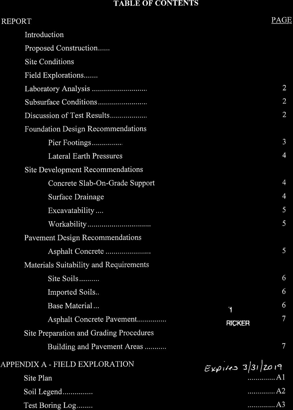
2 CIVIL Shephard-Wesnitzer, Inc. 110 W Dale Avenue Flagstaff, AZ Telephone: Fax: Contact: Ottis Begay obegay@swiaz.com ARCHITECT SPS+ Architects, LLP 8681 East Via de Negocio Scottsdale, AZ Telephone: Fax: Contact: Bob Pian Pian@spsplusarchitects.com Jeremy Bloomer jtbloomer@spsplusarchitects.com MECHANICAL / PLUMBING Applied Engineering 2800 South Rural Road Suite 101 Tempe, AZ Telephone: Fax: Contact: Greg Piraino gregp@appliedengineering.ws ELECTRICAL Electrical Design Consultants, Inc E Southern Avenue Suite 203 Mesa, AZ Telephone: Fax: Contact: Henry Valencia henry@edcinc.biz STRUCTURAL Caruso Turley Scott, Inc W. Rio Salado Parkway, Suite 200 Temp, AZ 8581 Telephone: Fax: Contact: Chris Atkinson catkinson@ctsaz.com PROJECT MANUAL DIABETES PREVENTION PROGRAM FITNESS TUBA CITY REGIONAL HEALTH CARE CORPORATION TUBA CITY, AZ (SPS+ Project No. 1641B) Dated: November 07, 2017 Pursuant to the Tuba City Regional Health Care Corporation and Job Order Contractor Agreement TABLE OF CONTENTS Statement of Work Quote Form Geotechnical Engineering Report Drainage Report Design Development Drawings including General Structural Notes and General Technical Specifications 1 page 5 pages 21 pages 58 pages 36 pages
3 Statement of Work [1641B] Page 1 PART 1 GENERAL 1.01 DEFINITIONS A. General Contractor is to be henceforth known as Job Order Contractor or JOC PROJECT SCHEDULE A. Schedule 1. Final Completion is due on 90 days from notice to proceed. B. Liquidated Damages 1. $250 per day for each calendar day substantial completion and or final completion is not achieved STATEMENT OF WORK A. New approximately 8,000 square foot modular building to include lobby, reception, screening room, workout rooms, office areas, kitchen training, restrooms and support services. General site will include utilities, parking and hardscaping to support building function. 1. JOC to verify water and sewer location, depth, capacity, volume and pressure before construction. 2. JOC to provide construction documents with current registered Architect/Engineer seals for building plan review and permits. JOC to coordinate and submit plans for review and subsequent permitting. 3. JOC to provide Navajo Nation Fire and Rescue sanctioned review and approval (permitting) by Brown and Associates. i. If a sprinkler system is required by the authority having jurisdiction, JOC to provide and install sprinkler system to meet current required building codes. Refer to Quote Form Alternate #2. 4. Note that the design development drawings and engineering details are for general information only. JOC registered Architect and Engineers may utilize alternative detailing and construction that meets or exceeds the performance of the proposed detailing SUBSURFACE INVESTIGATION A. A copy of a geotechnical report with respect to the building s site is included with this document: 1. Geotechnical Report entitled: Geotechnical Engineering Report, Diabetes Prevention Program Fitness, dated June 23, Prepared by: Ricker, Atkinson, McBee, Morman & Associates, Inc., RAMM Project No. G24105B. 3. This report identifies properties of below grade conditions and offers recommendations for the design of foundations, prepared primarily for the use of Architect. 4. The recommendations described shall not be construed as a requirement of this Contract, unless specifically referenced in the Contract Documents. 5. This report, by its nature cannot reveal all conditions that exist on the site. Should subsurface conditions be found to vary substantially from this report, changes in the design and construction of foundations will be made, with resulting credits or expenditures to the Contract Price accruing to Owner TECHNICAL SPECIFICATIONS A. Refer to General Technical Specifications on Sheet A200 for manufacturer and product data. END OF STATEMENT OF WORK
4 Quote Form [1641B] Page 1 TO: Tuba City Regional Health Care Corporation Attention: Julius Young II Director of Facilities Management 167 Main Street Tuba City, Arizona Pursuant to and in compliance with the Design Development Documents and Soils Investigation Report relating to the construction of: TUBA CITY REGIONAL HEALTH CARE CORPORATION DIABETES PREVENTION PROGRAM FITNESS NEW MODULAR BUILDING as prepared by SPS+ ARCHITECTS, LLP. This is to certify that the above Documents, as well as the sites upon which the work is to be constructed and any and all conditions affecting the work, have been carefully examined, the amount and nature of the work to be accomplished is thoroughly understood, and at no time, will misunderstanding of the Project Manual, Drawings, Specifications or conditions be contested. - CONTINUTED -
5 Quote Form [1641B] Page 2 2. BASE QUOTE to include the following items: JOC to attach detailed itemized quote cost information for each category in CSI format. a. Subcontractor and supplier cost: DOLLARS ($ ). b. JOC and General Conditions: DOLLARS ($ ). c. Owner s Contingency: Twenty-five thousand and no/ DOLLARS ($25, ). d. JOC Profit: DOLLARS ($ ). e. Performance and Payment Bonds: DOLLARS ($ ). f. Insurance: DOLLARS ($ ). g. Navajo Nation Tax: DOLLARS ($ ). h. State and County Tax: DOLLARS ($ ). i. JOC to provide Construction Documents with Architectural and Engineering registered seals for authority having jurisdiction review submittal: DOLLARS ($ ). j. Building Permit Review Fee: DOLLARS ($ ). k. Building Permit Fee: DOLLARS ($ ). l. Allowance for underground utilities unforeseen conditions: Ten thousand and no/ DOLLARS ($10, ). m. Other: DOLLARS ($ ). n. Other: DOLLARS ($ ). TOTAL BASE QUOTE: ( a through l plus others as occurs) DOLLARS ($ ). - CONTINUTED -
6 Quote Form [1641B] Page 3 3. ALTERNATE ITEMS (includes subcontractor and supplier costs, JOC and General Conditions, Owners Contingency, General Contractor Profit, Performance and Payment Bonds, Insurance, Navajo Nation Tax, State and County Tax): a. Alternate #1 Base Quote Low Slope Roof to be TPO or PVC with 10 year full system guarantee. Alternate to be Derbigum roof with 10 year full system guarantee. DOLLARS ($ ). b. Alternate #2 Base Quote does not include a sprinkler system. If authority having jurisdiction requires a sprinkler system, Alternate #2 to provide and install a current code compliant sprinkler system. Bid to include shop drawing creation and submittal/approval by Navajo Nation Fire and Rescue, Brown and Associates, and/or other required entities DOLLARS ($ ). - CONTINUTED -
7 Quote Form [1641B] Page 4 4. VOLUNTARY ALTERNATES JOC is invited to provide voluntary alternates to reduce the overall cost of the project. a. Voluntary Alternate #1: Cost: DOLLARS ($ ). b. Voluntary Alternate #2: Cost: DOLLARS ($ ). c. Voluntary Alternate #3: Cost: DOLLARS ($ ). d. Voluntary Alternate #3: Cost: DOLLARS ($ ). - CONTINUTED -
8 Quote Form [1641B] Page 5 5. In submitting this Quote, I (we) the undersigned agree: a. To hold my (our) Quote open for sixty (60) calendar days. b. Date of Substantial Completion: As noted in Statement of Work. c. Date of Final Completion: As noted in Statement of Work. d. The Owner reserves the right to reject any and all Quotes, or to waive or decline to waive any informality in any Quote. e. To enter into and execute an Agreement, if awarded on basis of this Quote, and to furnish Performance and Payment Bonds in the amount of one hundred (100%) percent of the total amount of Agreement. JOC Company Name: JOC Representative: Signed Date: END OF QUOTE FORM
9

10

11
12
13
14

15

16

17

18
19

20

21

22

23
24


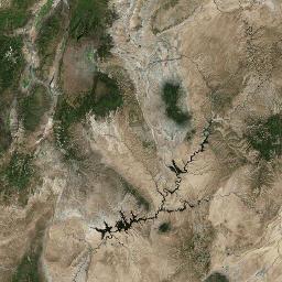
25


26

27

28

29

30 110 West Dale Avenue Flagstaff, AZ fax Engineering an environment of excellence. DRAINAGE REPORT for TUBA CITY REGIONAL HEALTHCARE CORPORATION HRSA COUNSELING CENTER AND DIABETES PREVENTION PROGRAM FITNESS A portion of Section 20 Township 32 North, Range 11 East, G&SRM Coconino County, Arizona Prepared for Tuba City Regional Healthcare Corporation Facilities Management Department 167 North Main St. PO Box 600 Tuba City, AZ Prepared by Shephard-Wesnitzer, Inc. Consulting Engineers 110 West Dale Avenue Flagstaff, Arizona /25/2017 July 25, 2017 Job #17095
31 TABLE OF CONTENTS INTRODUCTION... 1 OBJECTIVE... 1 PROCEDURE... 1 RESULTS... 2 CONCLUSION... 4 REFERENCES... 4 APPENDICES Appendix A Vicinity Map Appendix B Drainage Exhibit Appendix C Rational Method Calculations Appendix D Existing Pipe Capacity Appendix E StormCAD Output Appendix F PondPack Output
32 INTRODUCTION The addition of the Diabetes Prevention Program Fitness and HRSA Counseling Center buildings are proposed at the northeast corner of the Tuba City Healthcare Corporation campus. The project site is currently used as an unpaved parking area. The existing improvements on the site consist of the approximately 1 acre graded parking area and an existing storm drain pipe that crosses through the site. The site is located in Section 20, Township 32 North, Range 11 East, of the Gila and Salt River Meridian, Coconino County, Arizona. The improvements will include an 8,000 square foot modular building for the Diabetes Prevention Program Fitness facility, a 5,800 square foot modular building for the HRSA Counseling Center facility, adjacent parking and associated utility service connections. The existing site slopes to the southeast toward the existing fence at the property boundary. Offsite flows originating from the parking area and helipad to the west currently sheet flows onto the site. Offsite flows also enter the project site via the existing 24 diameter storm drain that ends at the proposed location for the Fitness building. A drainage ditch carries the flows to the property boundary. The project site is located within an area that is not mapped on the FEMA Flood Insurance Rate Maps. Appendix A includes a Vicinity Map with the location of the project site. OBJECTIVE The objective of this report is to determine the impact the proposed development will have on the runoff characteristics of the site. Mitigation measures will be provided for adverse impacts to the runoff conditions per the Coconino County Drainage Design Criteria (DDC). PROCEDURE The Rational Method was used to calculate peak discharge rates for the pre- and post-development conditions. Topographic survey information from Shephard Wesnitzer Inc., was used to determine the drainage patterns on the site. Boundary information was taken from the Boundary Survey Plat prepared by Surveying Control, Inc. Rainfall data was taken from the NOAA Atlas 14 rainfall Intensity-Duration-Frequency data for Tuba City, AZ found on the NOAA National Weather Service website. Soil information was taken from the NRCS Web Soil Survey website. The site plan prepared by the architect and proposed grading was used to determine the post-development drainage patterns on the site. Appendix B of this report includes a drainage exhibit showing the existing and proposed improvements, drainage patterns and drainage basin areas. The site plan was also used to determine the impervious areas proposed with the development. Rational C coefficients were determined based on existing site 1
33 conditions, proposed improvements and weighted based on coverage area. Figure 2-2 from the ADOT Highway Drainage Design Manual, Volume 2 Hydrology was used to determine the Rational C coefficient for the predevelopment conditions. The offsite drainage areas consist of the parking area and helipad located to the west and adjacent to the site, and a portion of the hospital building and parking nearest Elm Avenue. The stormwater runoff from the adjacent parking area and helipad currently sheet flows across the site and exits the property at the east boundary. Flows from the existing storm drain originate from the existing hospital building and the parking areas at the north side of the hospital. There are no existing drainage reports on file with the Hospital that details the hydrology and hydraulic calculations used to size the existing storm drain. The flow in the outlet pipe will be determined by calculating the full flow capacity of the pipe per Chapter 7 of the DDC. The proposed HRSA and Fitness buildings and the associated parking area will be graded to drain east to match the existing drainage patterns. A detention facility will be designed to offset the increase in peak discharge rates from the site in the post-development condition. Bentley s PondPack computer program was used to calculate the peak discharge rates, to design the proposed detention facility and size the outlet structure. The storm drain will be re-routed to create the area necessary for the Fitness building. Bentley s StormCAD computer program was used to size the proposed storm drain. RESULTS The Rational Method was used to calculate peak discharge rates used to size the proposed detention pond and storm drain. The runoff coefficients for the site in the pre-development condition were determined to be 0.33 in the 2- and 10-year storm event, and 0.41 in the 100-year storm event. In the post-development condition, the impervious areas were assigned a runoff coefficient of 0.95 and the landscape/pervious areas were assigned a runoff coefficient of The composite runoff coefficients for the site in the post-development condition were calculated to be 0.65 in the 2- and 10-year storm events, and 0.71 in the 100- year storm event. The offsite drainage basin that is located to the west and adjacent to the project site has an area of 0.87 acres. The composite runoff coefficients for the offsite drainage area were determined to be 0.87 in the 2- and 10-year storm event, and 0.93 in the 100-year storm event. The calculations for the runoff coefficients are included in appendix C. The time of concentration for the project site and offsite drainage area were determined to be 5 minutes. The table below summarizes the peak discharge rates for the pre- and postdevelopment conditions. 2
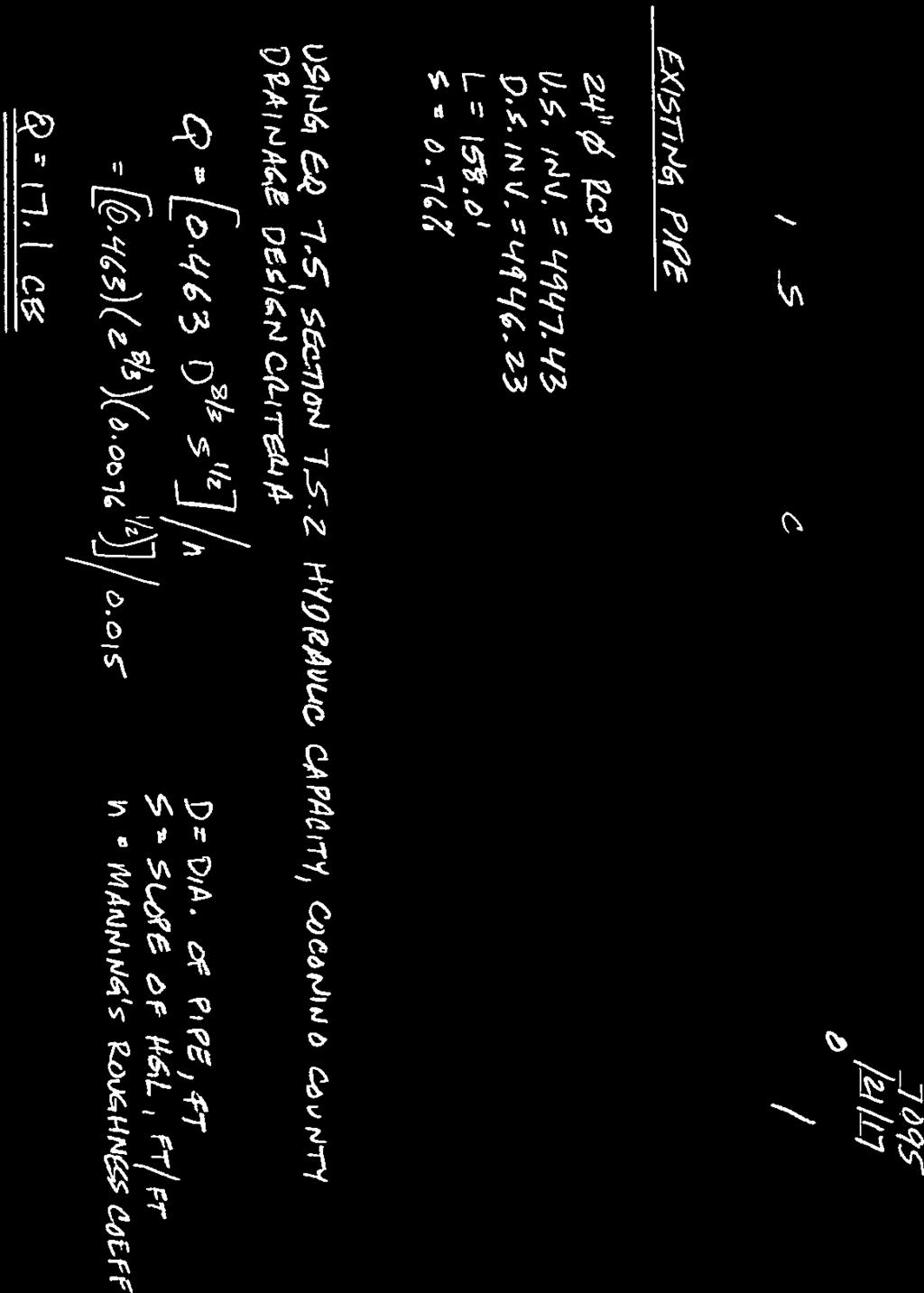
34 Scenario HRSA & Fitness Sites Table 1: Peak Discharge Rates (cfs) Area (acres) T c (mins.) C 2,10 C 100 Q 2 Q 10 Q 100 Pre-Development Post-development Offsite Drainage Basin Existing Condition The hydraulic capacity of the existing storm drain on the site was determined using Equation 7.5 in section Hydraulic Capacity from the DDC. The equation calculates the capacity of the pipes assuming the pipe is flowing full. Topographic survey information provided by SWI was used to determine the invert elevations of the downstream pipe to the existing storm drain. The pipe has a length of 158 feet and a slope of 0.76%. The capacity of the downstream 24 concrete pipe was calculated to be 17.1 cubic feet per second (cfs). The capacity calculations are included in appendix D of this letter. Bentley s StormCAD software was used to design the proposed storm drain. The proposed storm drain will be 24 diameter ADS N-12 HDPE pipe. The pipe has a manning s roughness coefficient of 0.012, allowing the pipe to have a minimum slope to meet the grades on the site. The storm drain will outlet to the proposed detention pond for the HRSA & Fitness buildings. An overflow weir will be included with the construction of the detention pond to allow the offsite flows to pass through the pond in the event that the pond was full. The StormCAD model for the proposed storm drain begins at the existing catch basin located to the north of the helipad. The StormCAD model for the proposed storm drain had a tailwater elevation set to the 100-year water surface elevation of the detention pond. ADS drain basins will be installed at changes in the storm drain alignment and the drain basins were modeled with the standard headloss method. Headloss coefficients for the drain basins were set according to the bend angle between the pipes entering and exiting the structure. The flow velocities in the pipes will range from 6.47 to 8.55 feet per second (ft/s). The flow velocities are within an acceptable range for the ADS N-12 HDPE pipe. The Hydraulic Grade Line (HGL) within the storm drain is within the pipes and at an acceptable depth below the rim elevation of the ADS drain basins. The StormCAD output, including design peak discharge rates, pipe capacities, flow velocities and the profile showing the HGL are included in Appendix E of this letter. The required storage capacity for the proposed detention pond was estimated to be 1,800 cubic feet during the 100-year, 39 minute storm event. The detention pond is designed as an above ground pond with a capacity of 2,397 cubic feet. The side slopes to the pond will be 3:1 (horizontal: vertical) and the fill 3
35 embankment will have a top width of 3 feet. The detention pond will have a bottom elevation of 4, and the top elevation of 4, The outlet to the pond will be a 12 diameter HDPE pipe to be located at the south end of the pond. The actual peak storage volume during the 39 minute, 100-year storm event was 1,359 cubic feet. The water surface elevation during the 100-year storm event was calculated to be 4, The pond will have an emergency riprap overflow weir to be located at the south end of the pond with a top elevation at the 100-year water surface elevation. The PondPack output is included in appendix F. CONCLUSION Peak discharges for the 2-, 10- and 100-year storm events were determined for the project site for both the pre- and post-development conditions. The proposed detention pond and outlet pipe are designed to reduce the post-development peak discharge rates to be below pre-development levels. No further detention of stormwater runoff is required. All drainage conveyance structures and detention facilities are designed per the requirements outlined in the DDC. Refer to the construction plans by SWI for grades, locations and notes. The design concepts in this report will ensure that the drainage integrity of the site is sustained with proper maintenance activity. Activities include frequent clearing of debris and sediment from the detention facility and catch basins, disturbed slope treatment and erosion control at the outlet pipe. Frequent monitoring will ensure expedient remedies to common problems such as erosion, sedimentation, and flow obstructions. REFERENCES Publications Coconino County Drainage Design Criteria, January 2001 Software StormCAD, Bentley Systems, Inc., Version 8i PondPack, Bentley Systems, Inc., Version 8i 4
36 Appendix A Vicinity Map
37
38 Appendix B Drainage Exhibit
39 8''SS 8''SS 8''SS 8''SS 8''SS 8''SS 8''SS 8''SS 8''SS 8''SS 8''SS 8''SS 8''SS 8''SS 8''SS 8''SS 8''SS 8''SS 8''SS 8''SS OHE OHE OHE S S S S 6''W 6''W 6''W OHE OHE OHE OHE S S S 6''W 6''W 6''W 6''W 6''W 6''W 6''W 6''W 6''W 6''W 6''W 4''G 4''G 4''G 4''G 4''G 4''G 4''G > 2''W 2''W 2''W 2''W 6''W 6''W 6''W 6''W 6''W 6''W 6''W 6''W 6''W 6''W 6''W 6''W 6''W Scenario Area (acres) Tc (min) 2-Year 10-Year 100-Year C i (in/hr) Q2 C i (in/hr) Q10 C i (in/hr) Q100 Pre-Development Post-Development Offisite
40 Appendix C Rational Method Calculations

41 111 17' 35'' W Hydrologic Soil Group Little Colorado River Area, Arizona, Parts of Coconino and Navajo Counties (TCRHCC (SWI# 14109)) ' 18'' W ' 38'' N 36 9' 38'' N ' 49'' N 36 5' 49'' N ' 35'' W N Map Scale: 1:49,900 if printed on A landscape (11" x 8.5") sheet. Meters Feet Map projection: Web Mercator Corner coordinates: WGS84 Edge tics: UTM Zone 12N WGS ' 18'' W Natural Resources Conservation Service Web Soil Survey National Cooperative Soil Survey 12/5/2014 Page 1 of 4
42 Hydrologic Soil Group Little Colorado River Area, Arizona, Parts of Coconino and Navajo Counties (TCRHCC (SWI# 14109)) MAP LEGEND MAP INFORMATION Area of Interest (AOI) Area of Interest (AOI) Soils Soil Rating Polygons A A/D B B/D C C/D D Not rated or not available Soil Rating Lines A A/D B B/D C C/D D Not rated or not available Soil Rating Points A A/D B B/D C C/D D Not rated or not available Water Features Streams and Canals Transportation Rails Interstate Highways US Routes Major Roads Local Roads Background Aerial Photography The soil surveys that comprise your AOI were mapped at 1:24,000. Please rely on the bar scale on each map sheet for map measurements. Source of Map: Natural Resources Conservation Service Web Soil Survey URL: Coordinate System: Web Mercator (EPSG:3857) Maps from the Web Soil Survey are based on the Web Mercator projection, which preserves direction and shape but distorts distance and area. A projection that preserves area, such as the Albers equal-area conic projection, should be used if more accurate calculations of distance or area are required. This product is generated from the USDA-NRCS certified data as of the version date(s) listed below. Soil Survey Area: Little Colorado River Area, Arizona, Parts of Coconino and Navajo Counties Survey Area Data: Version 8, Sep 20, 2014 Soil map units are labeled (as space allows) for map scales 1:50,000 or larger. Date(s) aerial images were photographed: 27, 2011 May 15, 2011 May The orthophoto or other base map on which the soil lines were compiled and digitized probably differs from the background imagery displayed on these maps. As a result, some minor shifting of map unit boundaries may be evident. Natural Resources Conservation Service Web Soil Survey National Cooperative Soil Survey 12/5/2014 Page 2 of 4
43 Hydrologic Soil Group Little Colorado River Area, Arizona, Parts of Coconino and Navajo Counties TCRHCC (SWI# 14109) Hydrologic Soil Group Hydrologic Soil Group Summary by Map Unit Little Colorado River Area, Arizona, Parts of Coconino and Navajo Counties (AZ707) Map unit symbol Map unit name Rating Acres in AOI Percent of AOI 7 Endoaquolls- Haplofibrists- Psammaquents complex, 0 to 3 percent slopes 16 Ives-Bebeevar family- Oxyaquic Torripsamments complex, 0 to 3 percent slopes 17 Ives-Jocity complex, 1 to 4 percent slopes 18 Ives-Riverwash association, 0 to 2 percent slopes 20 Jocity sandy clay loam, 0 to 2 percent slopes 22 Jocity-Tuba, complex, 1 to 3 percent slopes 36 Needle-Rock outcrop- Sheppard complex, 2 to 15 percent slopes A/D % B % A % A % B % C % D % 37 Nepalto family-tsaya- Rock outcrop complex, 35 to 70 percent slopes A % 51 Sheppard-Monue complex, 1 to 8 percent slopes 53 Sheppard-Rock outcrop- Sheppard, moderately deep complex, 2 to 15 percent slopes 55 Shoegame family, 1 to 5 percent slopes 57 Shorthair-Rock outcrop- Sheppard complex, 2 to 15 percent slopes 62 Tuba-Tyende family- Fajada family complex, 2 to 15 percent slopes A % A % A % D % B 7, % 64 Water % Totals for Area of Interest 10, % Natural Resources Conservation Service Web Soil Survey National Cooperative Soil Survey 12/5/2014 Page 3 of 4
44 Hydrologic Soil Group Little Colorado River Area, Arizona, Parts of Coconino and Navajo Counties TCRHCC (SWI# 14109) Description Hydrologic soil groups are based on estimates of runoff potential. Soils are assigned to one of four groups according to the rate of water infiltration when the soils are not protected by vegetation, are thoroughly wet, and receive precipitation from long-duration storms. The soils in the United States are assigned to four groups (A, B, C, and D) and three dual classes (A/D, B/D, and C/D). The groups are defined as follows: Group A. Soils having a high infiltration rate (low runoff potential) when thoroughly wet. These consist mainly of deep, well drained to excessively drained sands or gravelly sands. These soils have a high rate of water transmission. Group B. Soils having a moderate infiltration rate when thoroughly wet. These consist chiefly of moderately deep or deep, moderately well drained or well drained soils that have moderately fine texture to moderately coarse texture. These soils have a moderate rate of water transmission. Group C. Soils having a slow infiltration rate when thoroughly wet. These consist chiefly of soils having a layer that impedes the downward movement of water or soils of moderately fine texture or fine texture. These soils have a slow rate of water transmission. Group D. Soils having a very slow infiltration rate (high runoff potential) when thoroughly wet. These consist chiefly of clays that have a high shrink-swell potential, soils that have a high water table, soils that have a claypan or clay layer at or near the surface, and soils that are shallow over nearly impervious material. These soils have a very slow rate of water transmission. If a soil is assigned to a dual hydrologic group (A/D, B/D, or C/D), the first letter is for drained areas and the second is for undrained areas. Only the soils that in their natural condition are in group D are assigned to dual classes. Rating Options Aggregation Method: Dominant Condition Component Percent Cutoff: None Specified Tie-break Rule: Higher Natural Resources Conservation Service Web Soil Survey National Cooperative Soil Survey 12/5/2014 Page 4 of 4
45


46 Precipitation Frequency Data Server 1 of 4 6/6/17, 7:11 PM NOAA Atlas 14, Volume 1, Version 5 Location name: Tuba City, Arizona, USA* Latitude: , Longitude: Elevation: ft** * source: ESRI Maps ** source: USGS POINT PRECIPITATION FREQUENCY ESTIMATES Sanja Perica, Sarah Dietz, Sarah Heim, Lillian Hiner, Kazungu Maitaria, Deborah Martin, Sandra Pavlovic, Ishani Roy, Carl Trypaluk, Dale Unruh, Fenglin Yan, Michael Yekta, Tan Zhao, Geoffrey Bonnin, Daniel Brewer, Li-Chuan Chen, Tye Parzybok, John Yarchoan NOAA, National Weather Service, Silver Spring, Maryland PF_tabular PF_graphical Maps_&_aerials PF tabular PDS-based point precipitation frequency estimates with 90% confidence intervals (in inches/hour) 1 Duration 5-min 10-min 15-min 30-min 60-min 2-hr 3-hr 6-hr 12-hr 24-hr 2-day 3-day 4-day 7-day 10-day 20-day 30-day 45-day 60-day Average recurrence interval (years) ( ) 1.18 ( ) ( ) ( ) ( ) ( ) ( ) ( ) ( ) ( ) ( ) ( ) ( ) ( ) ( ) ( ) ( ) ( ) ( ) 1.99 ( ) 1.52 ( ) 1.25 ( ) ( ) ( ) ( ) ( ) ( ) ( ) ( ) ( ) ( ) ( ) ( ) ( ) ( ) ( ) ( ) ( ) 2.75 ( ) 2.09 ( ) 1.73 ( ) 1.17 ( ) ( ) ( ) ( ) ( ) ( ) ( ) ( ) ( ) ( ) ( ) ( ) ( ) ( ) ( ) ( ) 3.43 ( ) 2.62 ( ) 2.16 ( ) 1.45 ( ) ( ) ( ) ( ) ( ) ( ) ( ) ( ) ( ) ( ) ( ) ( ) ( ) ( ) ( ) ( ) 4.50 ( ) 3.43 ( ) 2.83 ( ) 1.91 ( ) 1.18 ( ) ( ) ( ) ( ) ( ) ( ) ( ) ( ) ( ) ( ) ( ) ( ) ( ) ( ) ( ) 5.44 ( ) 4.14 ( ) 3.42 ( ) 2.30 ( ) 1.43 ( ) ( ) ( ) ( ) ( ) ( ) ( ) ( ) ( ) ( ) ( ) ( ) ( ) ( ) ( ) 6.54 ( ) 4.98 ( ) 4.11 ( ) 2.77 ( ) 1.71 ( ) ( ) ( ) ( ) ( ) ( ) ( ) ( ) ( ) ( ) ( ) ( ) ( ) ( ) ( ) 1 Precipitation frequency (PF) estimates in this table are based on frequency analysis of partial duration series (PDS) ( ) 5.93 ( ) 4.90 ( ) 3.30 ( ) 2.04 ( ) 1.12 ( ) ( ) ( ) ( ) ( ) ( ) ( ) ( ) ( ) ( ) ( ) ( ) ( ) ( ) 9.72 ( ) 7.40 ( ) 6.12 ( ) 4.12 ( ) 2.55 ( ) 1.39 ( ) ( ) ( ) ( ) ( ) ( ) ( ) ( ) ( ) ( ) ( ) ( ) ( ) ( ) 11.4 ( ) 8.67 ( ) 7.17 ( ) 4.83 ( ) 2.99 ( ) 1.63 ( ) 1.10 ( ) ( ) ( ) ( ) ( ) ( ) ( ) ( ) ( ) ( ) ( ) ( ) ( ) Numbers in parenthesis are PF estimates at lower and upper bounds of the 90% confidence interval. The probability that precipitation frequency estimates (for a given duration and average recurrence interval) will be greater than the upper bound (or less than the lower bound) is 5%. Estimates at upper bounds are not checked against probable maximum precipitation (PMP) estimates and may be higher than currently valid PMP values. Please refer to NOAA Atlas 14 document for more information. Back to Top PF graphical

47 Precipitation Frequency Data Server 2 of 4 6/6/17, 7:11 PM Back to Top Maps & aerials Small scale terrain


48 Precipitation Frequency Data Server 3 of 4 6/6/17, 7:11 PM 3km + 2mi Large scale terrain 100km + 60mi Large scale map 100km + 60mi Large scale aerial


49 Precipitation Frequency Data Server 4 of 4 6/6/17, 7:11 PM Back to Top US Department of Commerce National Oceanic and Atmospheric Administration National Weather Service National Water Center 1325 East West Highway Silver Spring, MD Questions?: HDSC.Questions@noaa.gov Disclaimer
50 TCRHCC HRSA & Fitness SWI Job No Rational 'C' coefficient Calculations Existing Condition: C 2 & 10 yr = 0.33 C 100 yr = 0.33*1.25 = 0.41 (antecedent precipitation factor = 1.25) Notes: 1.) Uses ADOT Figure ) Land use is Desert 3.) Hydrologic Soil Group is 'B' Proposed Condition: C 2 & 10 yr Impervious Areas Area (ac.) = C = 0.95 C * Area = Open Space (for landscape and cut/fill areas) Area (ac.) = C = 0.33 C * Area = Composite 'C' coefficient = [(C * Area) impervious + (C * Area) open space ]/ Total Area = [ ] /0.66 = C 100 yr Impervious Areas Area (ac.) = C = 0.95*1.25 = 1.0 (antecedent precipitation factor = 1.25) C * Area = Open Space (for landscape and cut/fill areas) Area (ac.) = C = 0.33*1.25 = 0.41 (antecedent precipitation factor = 1.25) C * Area = Composite 'C' coefficient = [(C * Area) impervious + (C * Area) open space ]/ Total Area = [ ] / 0.66 =
51 TCRHCC HRSA & Fitness SWI Job No Rational 'C' coefficient Calculations, Offiste Drainage Basin Existing Condition: C 2 & 10 yr Impervious Areas Area (ac.) = C = 0.95 C * Area = Open Space (for landscape and cut/fill areas) Area (ac.) = C = 0.33 C * Area = Composite 'C' coefficient = [(C * Area) impervious + (C * Area) open space ]/ Total Area = [ ] /0.87 = C 100 yr Impervious Areas Area (ac.) = C = 0.95*1.25 = 1.0 (antecedent precipitation factor = 1.25) C * Area = Open Space (for landscape and cut/fill areas) Area (ac.) = C = 0.33*1.25 = (antecedent precipitation factor = 1.25) C * Area = Composite 'C' coefficient = [(C * Area) impervious + (C * Area) open space ]/ Total Area = [ ] / 0.87 = Notes: 1.) Uses ADOT Figure ) Land use is Desert 3.) Hydrologic Soil Group is 'B'
52 TCRHCC HRSA & Fitness SWI Job No Rational 'C' coefficient Calculations Scenario Area (acres) Tc (min) 2-Year 10-Year 100-Year C i (in/hr) Q 2 C i (in/hr) Q 10 C i (in/hr) Q 100 Pre-Development Post-Development Offisite Note: Rainfall intensity values taken from NOAA Atlas 14 for Tuba City, AZ
53 Appendix D Existing Pipe Capacity
54

55
56 Appendix E StormCAD Output
57 CO-3 Scenario: Base Active Scenario: Base CB-1 CO-1 MH-1 CO-2 MH-2 OF HRSA & Fitness.stc Active Scenario: Base Page 1 of 1 7/18/2017 Bentley Systems, Inc. Haestad Methods Solution Center 27 Siemon Company Drive Suite 200 W Watertown, CT USA Bentley StormCAD V8i (SELECTseries 2) [ ]
58 Conduit FlexTable: Combined Pipe/Node Report ( HRSA & Fitness.stc) Active Scenario: Base CO-1 CO-2 CO-3 Label Velocity (Average) (ft/s) CB-1 MH-1 MH-2 Start Node Hydraulic Grade Line (In) (ft) 4, , , MH-1 MH-2 OF-1 Stop Node Hydraulic Grade Line (Out) (ft) 4, , , Diameter (in) Froude Number Invert (Upstream) (ft) 4, , , Manning's n Invert (Downstream) (ft) , , , Length (Unified) (ft) Slope (ft/ft) Total Flow (ft³/s) Capacity (Full Flow) (ft³/s) HRSA & Fitness.stc Active Scenario: Base Page 1 of 1 7/18/2017 Bentley Systems, Inc. Haestad Methods Solution Center 27 Siemon Company Drive Suite 200 W Watertown, CT USA Bentley StormCAD V8i (SELECTseries 2) [ ]
59 FlexTable: Catch Basin Table ( HRSA & Fitness.stc) Active Scenario: Base CB-1 Label Downstream Conduit CO-1 Elevation (Ground) (ft) 4, Headloss (ft) 0.00 Elevation (Rim) (ft) 4, Elevation (Invert) (ft) 4, Flow (Additional) (ft³/s) 0.00 Flow (Known) (ft³/s) Flow (Total Out) (ft³/s) Hydraulic Grade Line (In) (ft) 4, Hydraulic Grade Line (Out) (ft) 4, Is Flooded? False HRSA & Fitness.stc Active Scenario: Base Page 1 of 1 7/18/2017 Bentley Systems, Inc. Haestad Methods Solution Center 27 Siemon Company Drive Suite 200 W Watertown, CT USA Bentley StormCAD V8i (SELECTseries 2) [ ]
60 FlexTable: Manhole Table ( HRSA & Fitness.stc) Active Scenario: Base MH-1 MH-2 Label Station (Calculated) (ft) Elevation (Ground) (ft) 4, , Set Rim to Ground Elevation? True True Elevation (Rim) (ft) 4, , Elevation (Invert) (ft) 4, , Bolted Cover? False False Diameter (in) Headloss Method Standard Standard HRSA & Fitness.stc Active Scenario: Base Page 1 of 1 7/18/2017 Bentley Systems, Inc. Haestad Methods Solution Center 27 Siemon Company Drive Suite 200 W Watertown, CT USA Bentley StormCAD V8i (SELECTseries 2) [ ]
61 FlexTable: Outfall Table ( HRSA & Fitness.stc) Active Scenario: Base OF-1 Label Station (ft) 0+00 Elevation (Ground) (ft) 4, Set Rim to Ground Elevation True Elevation (Invert) (ft) 4, Boundary Condition Type User Defined Tailwater Elevation (Tailwater) (ft) 4, HRSA & Fitness.stc Active Scenario: Base Page 1 of 1 7/18/2017 Bentley Systems, Inc. Haestad Methods Solution Center 27 Siemon Company Drive Suite 200 W Watertown, CT USA Bentley StormCAD V8i (SELECTseries 2) [ ]
62 Profile Report Engineering Profile - Profile - Proposed Storm Drain ( HRSA & Fitness.stc) Active Scenario: Base HRSA & Fitness.stc Active Scenario: Base Page 1 of 1 7/18/2017 Bentley Systems, Inc. Haestad Methods Solution Center 27 Siemon Company Drive Suite 200 W Watertown, CT USA Bentley StormCAD V8i (SELECTseries 2) [ ]
63 Appendix F PondPack Output
64 Project Summary Title Engineer Company Date TCRHCC HRSA & Fitness Ottis Begay, P.E. Shephard- Wesnitzer, Inc. 7/18/2017 Notes Design of proposed detention pond for HRSA and Fitness buildings HRSA and Fitness.ppc Shephard-Wesnitzer, Inc. 7/18/2017 Bentley Systems, Inc. Haestad Methods Solution Center 27 Siemon Company Drive Suite 200 W Watertown, CT USA Bentley PondPack V8i [ ] Page 1 of 23
65 Table of Contents User Notifications 2 Modified Rational Grand Summary Master Network Summary 3 4 User Defined IDF Table - TCRHCC User Defined IDF Table - TCRHCC - 10 Year HRSA & Fitness PO-1 Composite Outlet Structure - 1 HRSA & Fitness I-D-F Table I-D-F Table I-D-F Table Time of Concentration Calculations (Pre- Development) User Defined IDF Table - TCRHCC - 2 Year Elevation-Area Volume Curve Volume Equations Outlet Input Data User Defined IDF Table - TCRHCC - 2 Year Modified Rational Graph Modified Rational Storm Calculations Modified Rational Graph Modified Rational Storm Calculations C and Area (Pre- Development) C and Area (Post- Development) Modified Rational Graph Modified Rational Storm Calculations
66 Subsection: User Notifications User Notifications? No user notifications generated HRSA and Fitness.ppc Shephard-Wesnitzer, Inc. 7/18/2017 Bentley Systems, Inc. Haestad Methods Solution Center 27 Siemon Company Drive Suite 200 W Watertown, CT USA Bentley PondPack V8i [ ] Page 2 of 23
67 Subsection: Modified Rational Grand Summary Modified Rational Method Q = CiA * Units Conversion; Where conversion = / (12 * 3600) Frequency (years) Volume (Storage) (ft³) ,800 Area (ft²) 28,666 28,666 28,666 Adjusted C Coefficient Duration (hours) Intensity (in/h) Flow (Peak) (ft³/s) Flow (Allowable) (ft³/s) Volume (inflow) (ft³) 1,077 1,851 3, HRSA and Fitness.ppc Shephard-Wesnitzer, Inc. 7/18/2017 Bentley Systems, Inc. Haestad Methods Solution Center 27 Siemon Company Drive Suite 200 W Watertown, CT USA Bentley PondPack V8i [ ] Page 3 of 23
68 Subsection: Master Network Summary Catchments Summary Label HRSA & Fitness HRSA & Fitness HRSA & Fitness Scenario Post-Development 2yr Post-Development 10yr Post-Development 100yr Return Event (years) Hydrograph Volume (ft³) 1,060 1,822 3,477 Time to Peak (hours) Peak Flow (ft³/s) Node Summary O-1 O-1 O-1 Label Scenario Post-Development 2yr Post-Development 10yr Post-Development 100yr Return Event (years) Hydrograph Volume (ft³) 1,066 1,832 3,496 Time to Peak (hours) Peak Flow (ft³/s) Pond Summary Label Scenario Return Event (years) Hydrograph Volume (ft³) Time to Peak (hours) Peak Flow (ft³/s) Maximum Water Surface Elevation (ft) Maximum Pond Storage (ft³) PO-1 (IN) PO-1 (OUT) PO-1 (IN) PO-1 (OUT) PO-1 (IN) PO-1 (OUT) Post- Development 2yr Post- Development 2yr Post- Development 10yr Post- Development 10yr Post- Development 100yr Post- Development 100yr ,066 1,066 1,832 1,832 3,496 3, (N/A) 4, (N/A) 4, (N/A) 4, (N/A) 581 (N/A) 851 (N/A) 1, HRSA and Fitness.ppc Shephard-Wesnitzer, Inc. 7/18/2017 Bentley Systems, Inc. Haestad Methods Solution Center 27 Siemon Company Drive Suite 200 W Watertown, CT USA Bentley PondPack V8i [ ] Page 4 of 23
69 Subsection: I-D-F Table Label: User Defined IDF Table - TCRHCC Return Event: 10 years Storm Event: User Defined IDF Table - TCRHCC - 10 Year Time (hours) I-D-F Curve Intensity (in/h) HRSA and Fitness.ppc Shephard-Wesnitzer, Inc. 7/18/2017 Bentley Systems, Inc. Haestad Methods Solution Center 27 Siemon Company Drive Suite 200 W Watertown, CT USA Bentley PondPack V8i [ ] Page 5 of 23
70 Subsection: I-D-F Table Label: User Defined IDF Table - TCRHCC Return Event: 100 years Storm Event: User Defined IDF Table - TCRHCC Year Time (hours) I-D-F Curve Intensity (in/h) HRSA and Fitness.ppc Shephard-Wesnitzer, Inc. 7/18/2017 Bentley Systems, Inc. Haestad Methods Solution Center 27 Siemon Company Drive Suite 200 W Watertown, CT USA Bentley PondPack V8i [ ] Page 6 of 23
71 Subsection: I-D-F Table Label: User Defined IDF Table - TCRHCC Return Event: 2 years Storm Event: User Defined IDF Table - TCRHCC - 2 Year Time (hours) I-D-F Curve Intensity (in/h) HRSA and Fitness.ppc Shephard-Wesnitzer, Inc. 7/18/2017 Bentley Systems, Inc. Haestad Methods Solution Center 27 Siemon Company Drive Suite 200 W Watertown, CT USA Bentley PondPack V8i [ ] Page 7 of 23
72 Subsection: Time of Concentration Calculations (Pre- Development) Label: HRSA & Fitness Return Event: 100 years Storm Event: User Defined IDF Table - TCRHCC - 2 Year Time of Concentration Results (Pre-Development) Segment #1: TR-55 Sheet Flow Hydraulic Length Manning's n Slope 2 Year 24 Hour Depth Average Velocity Segment Time of Concentration ft (N/A) ft/ft 1.0 in 0.25 ft/s hours Segment #2: TR-55 Shallow Concentrated Flow Hydraulic Length Is Paved? Slope Average Velocity Segment Time of Concentration ft False ft/ft 2.55 ft/s hours Time of Concentration (Composite) Time of Concentration (Composite) hours HRSA and Fitness.ppc Shephard-Wesnitzer, Inc. 7/18/2017 Bentley Systems, Inc. Haestad Methods Solution Center 27 Siemon Company Drive Suite 200 W Watertown, CT USA Bentley PondPack V8i [ ] Page 8 of 23
73 Subsection: Time of Concentration Calculations (Pre- Development) Label: HRSA & Fitness Return Event: 100 years Storm Event: User Defined IDF Table - TCRHCC - 2 Year ==== SCS Channel Flow Tc = Where: R = Qa / Wp V = (1.49 * (R**(2/3)) * (Sf**-0.5)) / n (Lf / V) / 3600 R= Hydraulic radius Aq= Flow area, square feet Wp= Wetted perimeter, feet V= Velocity, ft/sec Sf= Slope, ft/ft n= Manning's n Tc= Time of concentration, hours Lf= Flow length, feet ==== SCS TR-55 Shallow Concentration Flow Unpaved surface: V = * (Sf**0.5) Tc = Where: Paved Surface: V = * (Sf**0.5) (Lf / V) / 3600 V= Velocity, ft/sec Sf= Slope, ft/ft Tc= Time of concentration, hours Lf= Flow length, feet HRSA and Fitness.ppc Shephard-Wesnitzer, Inc. 7/18/2017 Bentley Systems, Inc. Haestad Methods Solution Center 27 Siemon Company Drive Suite 200 W Watertown, CT USA Bentley PondPack V8i [ ] Page 9 of 23
74 Subsection: Elevation-Area Volume Curve Label: PO-1 Return Event: 100 years Storm Event: User Defined IDF Table - TCRHCC - 2 Year Elevation (ft) 4, , , Planimeter (ft²) Area (ft²) 1,360 1,951 2,375 A1+A2+sqr(A1*A 2) (ft²) 0 4,940 6,479 Volume (ft³) 0 1,317 1,080 Volume (Total) (ft³) 0 1,317 2, HRSA and Fitness.ppc Shephard-Wesnitzer, Inc. 7/18/2017 Bentley Systems, Inc. Haestad Methods Solution Center 27 Siemon Company Drive Suite 200 W Watertown, CT USA Bentley PondPack V8i [ ] Page 10 of 23
75 Subsection: Volume Equations Label: PO-1 Return Event: 100 years Storm Event: User Defined IDF Table - TCRHCC - 2 Year Pond Volume Equations * Incremental volume computed by the Conic Method for Reservoir Volumes. Volume = (1/3) * (EL2 - El1) * (Area1 + Area2 + sqr(area1 * Area2)) where: EL1, EL2 Area1, Area2 Volume Lower and upper elevations of the increment Areas computed for EL1, EL2, respectively Incremental volume between EL1 and EL HRSA and Fitness.ppc Shephard-Wesnitzer, Inc. 7/18/2017 Bentley Systems, Inc. Haestad Methods Solution Center 27 Siemon Company Drive Suite 200 W Watertown, CT USA Bentley PondPack V8i [ ] Page 11 of 23
76 Subsection: Outlet Input Data Label: Composite Outlet Structure - 1 Return Event: 100 years Storm Event: User Defined IDF Table - TCRHCC - 2 Year Requested Pond Water Surface Elevations Minimum (Headwater) Increment (Headwater) Maximum (Headwater) 4, ft 0.10 ft 4, ft Outlet Connectivity Structure Type Culvert-Circular Tailwater Settings Outlet ID Culvert - 1 Tailwater Direction Forward TW Outfall E1 (ft) 4, (N/A) E2 (ft) 4, (N/A) HRSA and Fitness.ppc Shephard-Wesnitzer, Inc. 7/18/2017 Bentley Systems, Inc. Haestad Methods Solution Center 27 Siemon Company Drive Suite 200 W Watertown, CT USA Bentley PondPack V8i [ ] Page 12 of 23
77 Subsection: Outlet Input Data Label: Composite Outlet Structure - 1 Return Event: 100 years Storm Event: User Defined IDF Table - TCRHCC - 2 Year Structure ID: Culvert - 1 Structure Type: Culvert-Circular Number of Barrels Diameter Length Length (Computed Barrel) Slope (Computed) in ft ft ft/ft Outlet Control Data Manning's n Ke Kb Kr Convergence Tolerance ft Inlet Control Data Equation Form K M C Y T1 ratio (HW/D) T2 ratio (HW/D) Slope Correction Factor Form Use unsubmerged inlet control 0 equation below T1 elevation. Use submerged inlet control 0 equation above T2 elevation In transition zone between unsubmerged and submerged inlet control, interpolate between flows at T1 & T2... T1 Elevation T2 Elevation 4, ft 4, ft T1 Flow T2 Flow 2.75 ft³/s 3.14 ft³/s HRSA and Fitness.ppc Shephard-Wesnitzer, Inc. 7/18/2017 Bentley Systems, Inc. Haestad Methods Solution Center 27 Siemon Company Drive Suite 200 W Watertown, CT USA Bentley PondPack V8i [ ] Page 13 of 23
78 Subsection: Outlet Input Data Label: Composite Outlet Structure - 1 Return Event: 100 years Storm Event: User Defined IDF Table - TCRHCC - 2 Year Structure ID: TW Structure Type: TW Setup, DS Channel Tailwater Type Free Outfall Convergence Tolerances Maximum Iterations Tailwater Tolerance (Minimum) Tailwater Tolerance (Maximum) Headwater Tolerance (Minimum) Headwater Tolerance (Maximum) Flow Tolerance (Minimum) Flow Tolerance (Maximum) ft 0.50 ft 0.01 ft 0.50 ft ft³/s ft³/s HRSA and Fitness.ppc Shephard-Wesnitzer, Inc. 7/18/2017 Bentley Systems, Inc. Haestad Methods Solution Center 27 Siemon Company Drive Suite 200 W Watertown, CT USA Bentley PondPack V8i [ ] Page 14 of 23
79 Subsection: Modified Rational Graph Label: HRSA & Fitness Return Event: 2 years Storm Event: User Defined IDF Table - TCRHCC - 2 Year Method Type Time of Duration (Modified Rational, Critical) Method I hours [1] [2] Time of Concentration (Modified Rational, Composite) Intensity (Modified Rational, Peak) Flow (Modified Rational, Peak) hours in/h ft³/s Time of Duration (Modified Rational, Critical) Intensity (Modified Rational, Critical) Flow (Modified Rational, Critical) hours in/h ft³/s [3] [4] Second Outflow Breakpoint (Modified Rational) Flow (Modified Rational, Allowable) hours ft³/s Storage (Modified Rational, Estimated) 549 ft³ HRSA and Fitness.ppc Shephard-Wesnitzer, Inc. 7/18/2017 Bentley Systems, Inc. Haestad Methods Solution Center 27 Siemon Company Drive Suite 200 W Watertown, CT USA Bentley PondPack V8i [ ] Page 15 of 23
80 Subsection: Modified Rational Storm Calculations Label: HRSA & Fitness Return Event: 2 years Storm Event: User Defined IDF Table - TCRHCC - 2 Year Modified Rational Method --- Summary for Single Storm Frequency --- C Coefficient (Weighted) Q = CiA * Units Conversion; Where Conversion = / (12 * 3600) C Coefficient (Adjusted) Duration (hours) Intensity (in/h) Area (ft²) 28,666 28,666 28,666 28,666 28,666 Flow (Peak) (ft³/s) Volume (Inflow) (ft³) Volume (Storage) (ft³) Storage Maximum , , ,666 28, ,089 (N/A) 549 (N/A) HRSA and Fitness.ppc Shephard-Wesnitzer, Inc. 7/18/2017 Bentley Systems, Inc. Haestad Methods Solution Center 27 Siemon Company Drive Suite 200 W Watertown, CT USA Bentley PondPack V8i [ ] Page 16 of 23
Summary of Detention Pond Calculation Canyon Estates American Canyon, California
 July 15, 2015 Bellecci & Associates, Inc Summary of Detention Pond Calculation Canyon Estates American Canyon, California 1. Methodology: Method: Unit Hydrograph Software: Bentley Pond Pack Version 8i
City of Fort Collins. Spring Creek Place (2105 South College Avenue) Preliminary Drainage Report
 Preliminary Drainage Report") City of Fort Collins Spring Creek Place (2105 South College Avenue) Preliminary Drainage Report OCTOBER 2016 VERSION 3 Prepared By: 4582 South Ulster Street, Suite 1500 Denver, CO 80237 Daniel L. Skeehan,
City of Fort Collins Spring Creek Place (2105 South College Avenue) Preliminary Drainage Report OCTOBER 2016 VERSION 3 Prepared By: 4582 South Ulster Street, Suite 1500 Denver, CO 80237 Daniel L. Skeehan,
North Omaha Ash Landfill Run-on and Run-off Control System Plan
 North Omaha Ash Landfill Run-on and Run-off Control System Plan Omaha Public Power District North Omaha Station Omaha, Nebraska October 17, 216 OPPD North Omaha Ash Landfill Run-On and Run-Off Control
NC2 Ash Disposal Area Run-on and Run-off Control System Plan
 NC2 Ash Disposal Area Run-on and Run-off Control System Plan Omaha Public Power District Nebraska City Station Nebraska City, Nebraska October 17, 2016 OPPD NC2 Ash Disposal Area Run-On and Run-Off Control
STORMWATER MANAGEMENT REPORT FOR THE BORGATA OUTDOOR EVENT AREA POOL ADDITION
 STORMWATER MANAGEMENT REPORT FOR THE BORGATA OUTDOOR EVENT AREA POOL ADDITION City of Atlantic City, Atlantic County, New Jersey Prepared For: Marina District Development Company, LLC One Borgata Way Atlantic
THE CITY OF THE VILLAGE PLANNED UNIT DEVELOPMENT DESIGN STATEMENT FOR MULFORD ESTATES
 THE CITY OF THE VILLAGE PLANNED UNIT DEVELOPMENT DESIGN STATEMENT FOR MULFORD ESTATES Revised August 18, 2016, August 10, 2016, September 19,2016 Prepared By: Isch and Associates, Inc. 14848 Bristol Park
DRAINAGE STUDY. 645 Beard Creek Trail Lot 8, Cordillera Valley Club Filing No. 4 Eagle County, Colorado. November 4, Project No.
 DRAINAGE STUDY 645 Beard Creek Trail Lot 8, Cordillera Valley Club Filing No. 4 Eagle County, Colorado November 4, 2014 Project No. 14-2953 Prepared for Mr. Robert Myers Caribbean Group P.O. Box N 1968
Inflow Design Flood Control System Plan
 Inflow Design Flood Control System Plan For Compliance with the Coal Combustion Residuals Rule (40 CFR Part 257) Valmont Station - CCR Surface Impoundments Public Service Company of Colorado Denver, Colorado
100-yr Design Runoff (cfs) Basin ID 103b A a B B C Totals
 Basin ID 103b A a B B C Totals") PROPOSED DEVELOPMENT The drainage for this site has been designed to be less than the maximum allowable runoff from each basin as stated in the Overall Rigden Farm drainage plan. Table 1 compares the actual
PROPOSED DEVELOPMENT The drainage for this site has been designed to be less than the maximum allowable runoff from each basin as stated in the Overall Rigden Farm drainage plan. Table 1 compares the actual
Site Description. CCR Rule Initial Inflow Design Flood Control System Plan (cont.) 2
 2") Site Description Kentucky Utilities Company (KU) owns and operates Ghent Gypsum Stack, a CCR surface impoundment, at the Ghent Generating Station in Carroll County, Kentucky. The impoundment is permitted
Site Description Kentucky Utilities Company (KU) owns and operates Ghent Gypsum Stack, a CCR surface impoundment, at the Ghent Generating Station in Carroll County, Kentucky. The impoundment is permitted
REFERENCE MAPS FEMA FIRM MAP NRCS SOILS MAP
 REFERENCE MAPS FEMA FIRM MAP NRCS SOILS MAP Hydrologic Soil Group-Hillsborough County, Florida (Independence Parkway) 27' 58' 56" 27" 58' 57" 2r 58' 32" 27" 58' 33" Map Scale: 1:5,290 if printed on A size
Drainage Letter for Falcon High School Building Expansion
 August 11, 2017 El Paso County Planning and Community Development Department 2880 International Circle, Suite 110 Colorado Springs, CO 80910 ATTN: RE: Mr. Jeff Rice Drainage Letter for Falcon High School
Stormwater Analysis Report
 Stormwater Analysis Report Solar Panel Array Temple Street (Rt. 14) West Boylston, MA February 24, 216 SITE Prepared for: West Boylston Municipal Lighting Plant 4 Crescent Street West Boylston, MA 1583
DRAINAGE STUDY. 645 Beard Creek Trail Lot 8, Cordillera Valley Club Filing No. 1 Eagle County, Colorado. November 25, Project No.
 DRAINAGE STUDY 645 Beard Creek Trail Lot 8, Cordillera Valley Club Filing No. 1 Eagle County, Colorado November 25, 2014 Project No. 14-2953 Prepared for Mr. Robert Myers Caribbean Group P.O. Box N 1968
Introduction to Storm Sewer Design
 A SunCam online continuing education course Introduction to Storm Sewer Design by David F. Carter Introduction Storm sewer systems are vital in collection and conveyance of stormwater from the upstream
Dawson County Public Works 25 Justice Way, Suite 2232, Dawsonville, GA (706) x 42228
 x 42228") Dawson County Public Works 25 Justice Way, Suite 2232, Dawsonville, GA 30534 (706) 344-3500 x 42228 DAWSON COUNTY STORM WATER REVIEW CHECKLIST Project Name: Property Address: Engineer: Fax #/Email: Date:
Dawson County Public Works 25 Justice Way, Suite 2232, Dawsonville, GA 30534 (706) 344-3500 x 42228 DAWSON COUNTY STORM WATER REVIEW CHECKLIST Project Name: Property Address: Engineer: Fax #/Email: Date:
INITIAL RUN-ON AND RUN-OFF CONTROLS PLAN NORTH VALMY GENERATING STATION (ASH LANDFILL) HUMBOLDT COUNTY, NEVADA OCTOBER 2016 PROJECT NO
 HUMBOLDT COUNTY, NEVADA OCTOBER 2016 PROJECT NO") INITIAL RUN-ON AND RUN-OFF CONTROLS PLAN NORTH VALMY GENERATING STATION (ASH LANDFILL) HUMBOLDT COUNTY, NEVADA OCTOBER 2016 PROJECT NO. 2016.R009 SUBMITTED TO: NV Energy, Inc. 6226 W. Sahara Ave. M/S 30
INITIAL RUN-ON AND RUN-OFF CONTROLS PLAN NORTH VALMY GENERATING STATION (ASH LANDFILL) HUMBOLDT COUNTY, NEVADA OCTOBER 2016 PROJECT NO. 2016.R009 SUBMITTED TO: NV Energy, Inc. 6226 W. Sahara Ave. M/S 30
RETENTION BASIN EXAMPLE
 -7 Given: Total Tributary Area = 7.5 ac o Tributary Area within Existing R/W = 5.8 ac o Tributary Area, Impervious, Outside of R/W = 0.0 ac o Tributary Area, Pervious, Outside of R/W = 1.7 ac o Tributary
SIZING WATER SERVICE LINES AND METERS
 SIZING WATER SERVICE LINES AND METERS COUNTY OF CURRITUCK Water Customer Data Sheet Customer: Address: Building Address: 2 Lark Drive Zip Code: Subdivision: Lot #: Block #: Type of Occupancy: FIXTURE FIXTURE
INFLOW DESIGN FLOOD CONTROL SYSTEM PLAN PLANT GREENE COUNTY ASH POND ALABMA POWER COMPANY
 INFLOW DESIGN FLOOD CONTROL SYSTEM PLAN PLANT GREENE COUNTY ASH POND ALABMA POWER COMPANY Section 257.82 of EPA s regulations requires the owner or operator of an existing or new CCR surface impoundment
Contents. Drainage Analysis: Hunters Trace, Westpointe, and Hunters Creek
 Drainage Analysis: Hunters Trace, Westpointe, and Hunters Creek Contents SITE LOCATION / DESCRIPTION... 3 WESTPOINTE STORMWATER MANAGEMENT PLAN... 3 THE ENCLAVE AT WESTPOINTE DETENTION POND... 3 Table
Hydrologic and Hydraulic Analysis Report Mountaineer Plant Bottom Ash Pond Complex New Haven, West Virginia
 Hydrologic and Hydraulic Analysis Report Mountaineer Plant Bottom Ash Pond Complex New Haven, West Virginia September 2015 Terracon Project Number: N4155129 Prepared for: American Electric Power 1 Riverside
January 20, Nate Hatleback Project Manager, City of Thornton Development Engineering 9500 Civic Center Drive Thornton, CO (303)
") January 20, 2017 Nate Hatleback Project Manager, City of Thornton Development Engineering 9500 Civic Center Drive Thornton, CO 80229 (303) 538-7694 RE: Riverdale Five Retail Drainage Conformance Letter
January 20, 2017 Nate Hatleback Project Manager, City of Thornton Development Engineering 9500 Civic Center Drive Thornton, CO 80229 (303) 538-7694 RE: Riverdale Five Retail Drainage Conformance Letter
Run-on and Run-off Control System Plan
 Run-on and Run-off Control System Plan J.H. CAMPBELL GENERATING FACILITY DRY ASH LANDFILL RUN-ON AND RUN-OFF CONTROL SYSTEM PLAN West Olive, Michigan Pursuant to 4 CFR 257.81 Submitted To: Consumers Energy
INFLOW DESIGN FLOOD CONTROL SYSTEM PLAN PLANT GASTON GYPSUM POND ALABAMA POWER COMPANY
 INFLOW DESIGN FLOOD CONTROL SYSTEM PLAN PLANT GASTON GYPSUM POND ALABAMA POWER COMPANY Section 257.82 of EPA s regulations requires the owner or operator of an existing or new CCR surface impoundment or
HYDROLOGIC-HYDRAULIC STUDY ISABELLA OCEAN RESIDENCES ISLA VERDE, CAROLINA, PR
 HYDROLOGIC-HYDRAULIC STUDY ISABELLA OCEAN RESIDENCES ISLA VERDE, CAROLINA, PR 1 INTRODUCTION 1.1 Project Description and Location Isabella Ocean Residences is a residential development to be constructed
Technical Memorandum
 Tucson Office 3031 West Ina Road Tucson, AZ 85741 Tel 520.297.7723 Fax 520.297.7724 www.tetratech.com Technical Memorandum To: Kathy Arnold From: Greg Hemmen, P.E. Company: Rosemont Copper Company Date:
NEW CASTLE CONSERVATION DISTRICT. through. (Name of Municipality) PLAN REVIEW APPLICATION DRAINAGE, STORMWATER MANAGEMENT, EROSION & SEDIMENT CONTROL
 PLAN REVIEW APPLICATION DRAINAGE, STORMWATER MANAGEMENT, EROSION & SEDIMENT CONTROL") NEW CASTLE CONSERVATION DISTRICT through (Name of Municipality) PLAN REVIEW APPLICATION DRAINAGE, STORMWATER MANAGEMENT, EROSION & SEDIMENT CONTROL Office use only: Received by Municipality: Received by
NEW CASTLE CONSERVATION DISTRICT through (Name of Municipality) PLAN REVIEW APPLICATION DRAINAGE, STORMWATER MANAGEMENT, EROSION & SEDIMENT CONTROL Office use only: Received by Municipality: Received by
ATTACHMENT 6 WATER QUALITY SWALE DESIGN ADDENDUM
 ATTACHMENT 6 WATER QUALITY SWALE DESIGN ADDENDUM 12 October 2010 Project No. 073-81694.0022 Mr. Robert R. Monok Project Manager Energy Fuels Resource Corporation 44 Union Boulevard, Suite 600 Lakewood,
RUN-ON AND RUN-OFF CONTROL SYSTEM PLAN
 RUN-ON AND RUN-OFF CONTROL SYSTEM PLAN FOR THE: SOUTHWESTERN ELECTRIC POWER COMPANY FLINT CREEK POWER PLANT LANDFILL CLASS 3N LANDFILL PERMIT 0273-S3N-R2 PREPARED FOR: SOUTHWESTERN ELECTRIC POWER COMPANY
INITIAL RUN-ON AND RUN-OFF CONTROL PLAN 40 C.F.R. PART 257
 INITIAL RUN-ON AND RUN-OFF CONTROL PLAN 40 C.F.R. PART 257.81 HUFFAKER ROAD (PLANT HAMMOND) PRIVATE INDUSTRIAL LANDFILL (HUFFAKER ROAD LANDFILL) GEORGIA POWER COMPANY EPA s Disposal of Coal Combustion
INFLOW DESIGN FLOOD CONTROL SYSTEM PLAN PLANT BARRY ASH POND ALABAMA POWER COMPANY
 INFLOW DESIGN FLOOD CONTROL SYSTEM PLAN PLANT BARRY ASH POND ALABAMA POWER COMPANY Section 257.82 of EPA s regulations requires the owner or operator of an existing or new CCR surface impoundment or any
Chapter 6. Hydrology. 6.0 Introduction. 6.1 Design Rainfall
 6.0 Introduction This chapter summarizes methodology for determining rainfall and runoff information for the design of stormwater management facilities in the City. The methodology is based on the procedures
Chapter 4. Drainage Report and Construction Drawing Submittal Requirements
 4.0 Introduction The requirements presented in this section shall be used to aid the design engineer or applicant in the preparation of drainage reports, drainage studies, and construction drawings for
Project Drainage Report
 Design Manual Chapter 2 - Stormwater 2A - General Information 2A-4 Project Drainage Report A. Purpose The purpose of the project drainage report is to identify and propose specific solutions to stormwater
Inflow Design Flood Control System Plan
 Inflow Design Flood Control System Plan B.C. COBB GENERATING FACILITY BOTTOM ASH POND INFLOW DESIGN FLOOD CONTROL SYSTEM PLAN Muskegon, Michigan Pursuant to 40 CFR 257.82 Submitted To: Consumers Energy
LAKE COUNTY HYDROLOGY DESIGN STANDARDS
 LAKE COUNTY HYDROLOGY DESIGN STANDARDS Lake County Department of Public Works Water Resources Division 255 N. Forbes Street Lakeport, CA 95453 (707)263-2341 Adopted June 22, 1999 These Standards provide
INFLOW DESIGN FLOOD CONTROL SYSTEM PLAN 40 C.F.R. PART PLANT YATES ASH POND 3 (AP-3) GEORGIA POWER COMPANY
 GEORGIA POWER COMPANY") INFLOW DESIGN FLOOD CONTROL SYSTEM PLAN 40 C.F.R. PART 257.82 PLANT YATES ASH POND 3 (AP-3) GEORGIA POWER COMPANY EPA s Disposal of Coal Combustion Residuals from Electric Utilities Final Rule (40 C.F.R.
INFLOW DESIGN FLOOD CONTROL SYSTEM PLAN 40 C.F.R. PART 257.82 PLANT YATES ASH POND 3 (AP-3) GEORGIA POWER COMPANY EPA s Disposal of Coal Combustion Residuals from Electric Utilities Final Rule (40 C.F.R.
INFLOW DESIGN FLOOD CONTROL SYSTEM PLAN 40 C.F.R. Part PLANT MCINTOSH ASH POND 1 GEORGIA POWER COMPANY
 INFLOW DESIGN FLOOD CONTROL SYSTEM PLAN 40 C.F.R. Part 257.82 PLANT MCINTOSH ASH POND 1 GEORGIA POWER COMPANY EPA s Disposal of Coal Combustion Residuals from Electric Utilities Final Rule (40 C.F.R. Part
Stormwater Erosion Control & Post-Construction Plans (Stormwater Quality Plans)
") Stormwater Erosion Control & Post-Construction Plans (Stormwater Quality Plans) Allen County Stormwater Plan Submittal Checklist The following items must be provided when applying for an Allen County Stormwater
Stormwater Erosion Control & Post-Construction Plans (Stormwater Quality Plans) Allen County Stormwater Plan Submittal Checklist The following items must be provided when applying for an Allen County Stormwater
BMP Design Aids. w w w. t r a n s p o r t a t i o n. o h i o. g o v. Equations / Programs
 BMP Design Aids 1 Equations / Programs Outlet Discharge Equations Hydrograph and Pond Routing Programs USGS StreamStats 2 Ohio Department of Transportation 1 Training Intent Introduction and overview of
APPENDIX G HYDRAULIC GRADE LINE
 Storm Drainage 13-G-1 APPENDIX G HYDRAULIC GRADE LINE 1.0 Introduction The hydraulic grade line is used to aid the designer in determining the acceptability of a proposed or evaluation of an existing storm
INITIAL RUN-ON AND RUN-OFF CONTROL PLAN 40 C.F.R. PART 257
 INITIAL RUN-ON AND RUN-OFF CONTROL PLAN 40 C.F.R. PART 257.81 PLANT BOWEN PRIVATE INDUSTRY SOLID WASTE DISPOSAL FACILITY (ASH LANDFILL) GEORGIA POWER COMPANY EPA s Disposal of Coal Combustion Residuals
Report. Inflow Design Flood Control System Plan Belle River Power Plant East China, Michigan. DTE Energy Company One Energy Plaza, Detroit, MI
 Report Inflow Design Flood Control System Plan Belle River Power Plant East China, Michigan DTE Energy Company One Energy Plaza, Detroit, MI October 14, 2016 NTH Project No. 62-160047-04 NTH Consultants,
Report. Inflow Design Flood Control System Plan St. Clair Power Plant St. Clair, Michigan. DTE Energy Company One Energy Plaza, Detroit, MI
 Report Inflow Design Flood Control System Plan St. Clair Power Plant St. Clair, Michigan DTE Energy Company One Energy Plaza, Detroit, MI October 14, 2016 NTH Project No. 62-160047-04 NTH Consultants,
Water Resources Management Plan
 P L Y M O U T H M I N N E S O T A Appendix D: The developed a to analyze and minimize the impact of existing and future development on the City s natural resources. It is important to the City to have
COMPUTER APPLICATIONS HYDRAULIC ENGINEERING
 - 7535 COMPUTER APPLICATIONS IN HYDRAULIC ENGINEERING Connecting Theory to Practice Fifth Edition HAESTAD PRESS Table of Contents Revision History Foreword CHAPTER 1 BASIC HYDRAULIC PRINCIPLES 1 1.1 General
SAMPLE DRAINAGE STATEMENT
 Firm Name & Logo Hidalgo County Drainage District No. 1 Drainage Statement Subdivision Name Hidalgo County, Texas Prepared By: Firm's Name Address City, State, Zip Telephone Fax Email Date SAMPLE DRAINAGE
FINAL DRAINAGE REPORT CORNERSTONE RIVER VALLEY VILLAGE FILING NO. 1 CITY OF THORNTON, COUNTY OF ADAMS, STATE OF COLORADO
 FINAL DRAINAGE REPORT CORNERSTONE RIVER VALLEY VILLAGE FILING NO. 1 CITY OF THORNTON, COUNTY OF ADAMS, STATE OF COLORADO PREPARED FOR: Thornton Cornerstone LLC 558 Castle Pines Parkway Suite B4-321 Castle
Drainage Report. PDC Energy Metcalf Soil Treatment Facility. OA Project No
 Drainage Report PDC Energy Metcalf Soil Treatment Facility OA Project No. 013-0036 760 Horizon Drive, Suite 102 Grand Junction, CO 81506 TEL 970.263.7800 FAX 970.263.7456 DRAINAGE REPORT PDC METCALF CENTRALIZED
Stormwater Management Studies PDS Engineering Services Division ES Policy # 3-01
 Stormwater Management Studies PDS Engineering Services Division Revised Date: 2/28/08 INTRODUCTION The City of Overland Park requires submission of a stormwater management study as part of the development
State Standard. for. Stormwater Detention/Retention
 ARIZONA DEPARTMENT OF WATER RESOURCES FLOOD MITIGATION SECTION State Standard for Stormwater Detention/Retention Under the authority outlined in ARS 48-3605(a) the Director of the Arizona Department of
CUYAHOGA COUNTY ENGINEER
 CUYAHOGA COUNTY ENGINEER DRAINAGE MANUAL Supplement to O.D.O.T. LOCATION and DESIGN MANUAL, Volume 2, Drainage Design, Section 1000 and 1100 May 28, 2010 Revisions to the July 29, 2009 edition are noted
Module 3: Rainfall and Hydrology for Construction Site Erosion Control
 Module 3: Rainfall and Hydrology for Construction Site Erosion Control Robert Pitt Department of Civil, Construction, and Environmental Engineering University of Alabama Tuscaloosa, AL Rainfall and Hydrology
Initial Inflow Design Flood Control System Plan Holding Pond
 Submitted to: Submitted by: Marquette Board of Light and Power AECOM Shiras Steam Plant Marquette, Michigan Marquette, Michigan Project No. 60445171 October 2016 Initial Inflow Design Flood Control System
Inflow Design Flood Control System Plan
 Inflow Design Flood Control System Plan For Compliance with the Coal Combustion Residuals Rule (40 CFR Part 257) Cherokee Station - CCR Surface Impoundments Public Service Company of Colorado Denver, Colorado
STORMWATER RUN-ON AND RUN-OFF CONTROL PLAN ENTERGY ARKANSAS, INC. WHITE BLUFF PLANT CLASS 3N CCR LANDFILL
 STORMWATER RUN-ON AND RUN-OFF CONTROL PLAN ENTERGY ARKANSAS, INC. WHITE BLUFF PLANT CLASS 3N CCR LANDFILL PERMIT NO. 199-S3N-R3 AFIN: 3-11 OCTOBER 13, 216 STORMWATER RUN-ON AND RUN-OFF CONTROL PLAN ENTERGY
INFLOW DESIGN FLOOD CONTROL SYSTEM PLAN 40 C.F.R. PART PLANT YATES ASH POND B (AP-B ) GEORGIA POWER COMPANY
 GEORGIA POWER COMPANY") INFLOW DESIGN FLOOD CONTROL SYSTEM PLAN 40 C.F.R. PART 257.82 PLANT YATES ASH POND B (AP-B ) GEORGIA POWER COMPANY EPA s Disposal of Coal Combustion Residuals from Electric Utilities Final Rule (40 C.F.R.
INFLOW DESIGN FLOOD CONTROL SYSTEM PLAN 40 C.F.R. PART 257.82 PLANT YATES ASH POND B (AP-B ) GEORGIA POWER COMPANY EPA s Disposal of Coal Combustion Residuals from Electric Utilities Final Rule (40 C.F.R.
RUN-ON AND RUN-OFF CONTROL PLAN 40 C.F.R. PART PLANT DANIEL NORTH ASH MANAGEMENT UNIT MISSISSIPPI POWER COMPANY
 RUN-ON AND RUN-OFF CONTROL PLAN 40 C.F.R. PART 257.81 PLANT DANIEL NORTH ASH MANAGEMENT UNIT MISSISSIPPI POWER COMPANY EPA s Disposal of Coal Combustion Residuals from Electric Utilities Final Rule (40
TOWN OF MANCHESTER PLANNING AND ZONING COMMISSION Subdivision Application Minimum Submission Requirements
 TOWN OF MANCHESTER PLANNING AND ZONING COMMISSION Subdivision Application Minimum Submission Requirements This checklist is to be completed and submitted with all Subdivision Applications. The Town reserves
Final Drainage Report
 Thornton Electric Substation Project Final Drainage Report December 14, 2016 DRAFT Prepared for: Xcel Energy, 1800 Larimer Street, Suite 400, Denver, Colorado 80202 Prepared by: 350 Indiana Street, Suite
Extended Detention Basin Design
 Extended Detention Basin Design 1 Extended Detention 2 Ohio Department of Transportation 1 Extended Detention Basin L&D Vol. 2 Section 1117.3 Provides quality and quantity treatment 3 Extended Detention
CHELTENHAM TOWNSHIP Chapter 290: WATERSHED STORMWATER MANAGEMENT Article IV: Stormwater Management
 CHELTENHAM TOWNSHIP Chapter 290: WATERSHED STORMWATER MANAGEMENT Article IV: Stormwater Management Online ECode Available on Cheltenham Township Website at: http://ecode360.com/14477578 For all regulated
PRELIMINARY DRAINAGE STUDY
 PRELIMINARY DRAINAGE STUDY For 34 th & J Residences 3402 J St. San Diego, CA 92102 A.P.N 545-250-08 Prepared By: Kenneth J. Discenza, P.E. Site Design Associates, Inc. 1016 Broadway, Suite A El Cajon,
PART 3 - STANDARDS FOR SEWERAGE FACILITIES DESIGN OF STORM SEWERS
 PART 3 - STANDARDS FOR SEWERAGE FACILITIES 3.3 - DESIGN OF STORM SEWERS 3.301 Design of Storm Sewers A. General Information B. Investigations and Surveys C. Special Projects 3.302 Design Criteria for Storm
FINAL DRAINAGE REPORT FOR: LOT 1 BLOCK 1 ROLLINS SUBDIVISION FILING #5. Prepared for:
 215063FD1 2014-3046 01J FINAL DRAINAGE REPORT FOR: LOT 1 BLOCK 1 ROLLINS SUBDIVISION FILING #5 Prepared for: Mr. Hari Sach RV America 3640 N. Chambers Road Aurora, Co. 80011 Phone: 303-360-0252 Email:
Jacobi, Toombs, and Lanz, Inc.
 Area 5: Blackiston Mill Road at Dead Man's Hollow Flooding Assessment Jacobi, Toombs, and Lanz, Inc. This document summarizes an assessment of drainage and flooding concerns and provides recommendations
Drainage Analysis. Appendix E
 Drainage Analysis Appendix E The existing and proposed storm drainage systems have been modeled with Bentley CivilStorm V8 computer modeling software. The peak stormwater discharge was determined for
Environmental Design Group
 SEDIMENT CONTROL DURING CONSTRUCTION, STORMWATER MANAGEMENT AND POST CONSTRUCTION BMP REPORT for Hudson Salt Storage and Bus Garage 5810 Hudson Drive HUDSON, OHIO SUMMIT COUNTY Prepared by Environmental
Runoff Calculations. Time of Concentration (T c or t c ) from one location to another within a watershed. Travel
 from one location to another within a watershed. Travel") Runoff Calculations Bob Pitt University of Alabama and Shirley Clark Penn State Harrisburg Time of Concentration and Travel Time (based on Chapter 3 of TR-55) Time of Concentration (T c ): time required
Runoff Calculations Bob Pitt University of Alabama and Shirley Clark Penn State Harrisburg Time of Concentration and Travel Time (based on Chapter 3 of TR-55) Time of Concentration (T c ): time required
CCR Certification: Initial Inflow Design Flood Control System Plan for the
 Submitted to Southern Indiana Gas & Electric Company dba Vectren Power Supply, Inc. (SIGECO) One Vectren Square Evansville, IN 4778 Submitted by AECOM 94 Amberglen Boulevard Austin, Texas 78729 October
Run-On and Run-Off Control System Plan Neal North Energy Center Monofill
 Run-On and Run-Off Control System Plan Neal North Energy Center Monofill MidAmerican Energy Company, Neal North Energy Center Coal Combustion Residual Rule Compliance October 10, 2016 Run-On and Run-Off
APPENDIX F RATIONAL METHOD
 7-F-1 APPENDIX F RATIONAL METHOD 1.0 Introduction One of the most commonly used procedures for calculating peak flows from small drainages less than 200 acres is the Rational Method. This method is most
STORMWATER RUN-ON AND RUN-OFF CONTROL PLAN ENTERGY ARKANSAS, INC. INDEPENDENCE PLANT CLASS 3N CCR LANDFILL
 STORMWATER RUN-ON AND RUN-OFF CONTROL PLAN ENTERGY ARKANSAS, INC. INDEPENDENCE PLANT CLASS 3N CCR LANDFILL PERMIT NO. 0200-S3N-R2 AFIN: 32-00042 OCTOBER 12, 2016 STORMWATER RUN-ON AND RUN-OFF CONTROL PLAN
Arvada Plaza Redevelopment. Walmart Store # (Lot 1) Industrial Realty Group, LLC (Lot 2)
 Industrial Realty Group, LLC (Lot 2)") Drainage Analysis Arvada, CO Arvada Plaza Redevelopment Including: Walmart Store #4734-00 (Lot 1) & Industrial Realty Group, LLC (Lot 2) (W 58 th Ave & Independence Street) Arvada, Colorado Preliminary
Drainage Analysis Arvada, CO Arvada Plaza Redevelopment Including: Walmart Store #4734-00 (Lot 1) & Industrial Realty Group, LLC (Lot 2) (W 58 th Ave & Independence Street) Arvada, Colorado Preliminary
3.3 Acceptable Downstream Conditions
 iswm TM Criteria Manual - = Not typically used or able to meet design criterion. 1 = The application and performance of proprietary commercial devices and systems must be provided by the manufacturer and
PEARCE CREEK CONFINED DISPOSAL AREA MODIFICATION
 US Army Corps of Engineers Philadelphia District PEARCE CREEK CONFINED DISPOSAL AREA MODIFICATION CECIL COUNTY MARYLAND STORMWATER MANAGEMENT PLAN NARRATIVE INITIAL SUBMISSION JUNE 2014 1 PEARCE CREEK
LDS Technical Guidance
 May 21, 2008 The following was provided to County staff as internal guidance for reviewers in applying the adequate outfall requirements of the Public Facilities Manual (PFM). A number of private sector
Rational Method Hydrological Calculations with Excel COURSE CONTENT
 Rational Method Hydrological Calculations with Excel Harlan H. Bengtson, PhD, P.E. COURSE CONTENT 1. Introduction Calculation of peak storm water runoff rate from a drainage area is often done with the
CUYAHOGA COUNTY DEPARTMENT OF PUBLIC WORKS CUYAHOGA COUNTY ENGINEER DRAINAGE MANUAL
 CUYAHOGA COUNTY DEPARTMENT OF PUBLIC WORKS CUYAHOGA COUNTY ENGINEER DRAINAGE MANUAL Supplement to O.D.O.T. LOCATION and DESIGN MANUAL, Volume 2, Drainage Design, Section 1000 and 1100 July 29, 2011 Revisions
STORMWATER HYDROLOGY
 ..CHAPTER.. STORMWATER HYDROLOGY 3.1 Introduction to Hydrologic Methods Hydrology is the science dealing with the characteristics, distribution, and movement of water on and below the earth's surface and
TxDOT Houston District Permit Requirements (Information contained herein is subject to change)
") Houston District Permit Requirements (Information contained herein is subject to change) Access Driveway for Commercial / Industrial Developments; or Street Tie-In / Drainage-Only 1) Complete the three
Houston District Permit Requirements (Information contained herein is subject to change) Access Driveway for Commercial / Industrial Developments; or Street Tie-In / Drainage-Only 1) Complete the three
ENGINEERING REVIEW CHECKLIST City of Mount Clemens
 (To be completed by the Developer s & Submitted with ing Plans) DATE: PROJECT NAME: Site Plan Approved: Date DESIGN ENGINEERING COMPANY: ing Company Contact Information: Name: Phone: Email: Owner Contact
Web Soil Survey National Cooperative Soil Survey
 99 52' 37'' W Yields of Irrigated Crops (Component): Cotton lint (Lbs) Haskell County, Texas 99 51' 40'' W 33 21' 4'' N 418500 418600 418700 418800 418900 419000 419100 419200 419300 419400 419500 419600
CUYAHOGA COUNTY DEPARTMENT OF PUBLIC WORKS CUYAHOGA COUNTY ENGINEER DRAINAGE MANUAL
 CUYAHOGA COUNTY DEPARTMENT OF PUBLIC WORKS CUYAHOGA COUNTY ENGINEER DRAINAGE MANUAL Supplement to O.D.O.T. LOCATION and DESIGN MANUAL, Volume 2, Drainage Design, Section 1000 and 1100 November 18, 2013
CONSTRUCTION PLAN CHECKLIST
 CONSTRUCTION PLAN CHECKLIST The design engineer is responsible for ensuring that plans submitted for city review are in accordance with this checklist. It is requested that the executed checklist be submitted
4.1 General Methodology and Data Base Development
 Chapter 4 METHODOLOGY 4.1 General and Data Base Development This report project utilized several computer software models and analysis techniques to create the numeric data on which decisions for this
FEMA (from current study - not yet adopted) Flow Data Table 2 Summary of Discharges Floodway Data
 Flow Data Table 2 Summary of Discharges Floodway Data") Table of Contents Report Cover Table of Contents General Information Methodology Existing Condition Analysis Proposed Condition Analysis Summary Conclusions and Recommendations Appendix Maps and Exhibits
Table of Contents Report Cover Table of Contents General Information Methodology Existing Condition Analysis Proposed Condition Analysis Summary Conclusions and Recommendations Appendix Maps and Exhibits
PART V - STORM DRAIN DESIGN CRITERIA
 PART V - STORM DRAIN DESIGN CRITERIA A. Hydrology Studies and Hydraulic Analyses 1. Drainage area master plans and calculations are to be submitted with all subdivision improvement plans, permit improvement
PART V - STORM DRAIN DESIGN CRITERIA
 PART V - STORM DRAIN DESIGN CRITERIA A. Hydrology Studies and Hydraulic Analyses 1. Drainage area master plans and calculations are to be submitted with all subdivision improvement plans, permit improvement
Submittal Requirements. Post Construction Verification Document Plan Requirements
 Submittal Requirements Post Construction Verification Document survey plan in accordance with the items of this Checklist Supporting calculations in accordance with the items of this Checklist A copy of
FORT COLLINS STORMWATER CRITERIA MANUAL Hydrology Standards (Ch. 5) 1.0 Overview
 1.0 Overview") Chapter 5: Hydrology Standards Contents 1.0 Overview... 1 1.1 Storm Runoff Determination... 1 1.2 Design Storm Frequencies... 1 1.3 Water Quality Storm Provisions... 2 1.4 Design Storm Return Periods...
Chapter 5: Hydrology Standards Contents 1.0 Overview... 1 1.1 Storm Runoff Determination... 1 1.2 Design Storm Frequencies... 1 1.3 Water Quality Storm Provisions... 2 1.4 Design Storm Return Periods...
Green Station CCR Surface Impoundment
 Green Station CCR Surface Impoundment Disposal of Coal Combustion Residuals (CCR) from Electric Utilities Final Rule Hydrologic and Hydraulic Capacity Assessment and Initial Inflow Design Flood Control
A Stormwater Management Plan and Sediment Control Plan are required for all proposed developments within the City of Richmond.
 Engineering Page 3-1 3.0 STORM DRAINAGE 3.1 GENERAL Good drainage is vital to flat urban areas such as Lulu Island. It is essential that every storm sewer must be designed accurately minimizing conflicts
APPENDIX E APPENDIX E ESTIMATING RUNOFF FOR SMALL WATERSHEDS
 APPENDIX E ESTIMATING RUNOFF FOR SMALL WATERSHEDS March 18, 2003 This page left blank intentionally. March 18, 2003 TABLES Table E.1 Table E.2 Return Frequencies for Roadway Drainage Design Rational Method
STORM WATER REPORT. Proposed Row House Complex Clare and Hilson 566 Hilson Ave. & 148 Clare St. Ottawa, Ontario PREPARED FOR:
 Civil Geotechnical Structural Environmental 210 Prescott Street, Unit 1 (613) 860-0923 P.O. Box 189 Kemptville, Ontario K0G 1J0 FAX: (613) 258-0475 STORM WATER REPORT Proposed Row House Complex Clare and
Detention Pond Design Considering Varying Design Storms. Receiving Water Effects of Water Pollutant Discharges
 Detention Pond Design Considering Varying Design Storms Land Development Results in Increased Peak Flow Rates and Runoff Volumes Developed area Robert Pitt Department of Civil, Construction and Environmental
Report Issued: July 26, 2017 Revision 1
 ALLIANT ENERGY Interstate Power and Light Company Burlington Generating Station CCR SURFACE IMPOUNDMENT INFLOW DESIGN FLOOD CONTROL PLAN Report Issued: July 26, 2017 Revision 1 EXECUTIVE SUMMARY This Inflow
TOWN OF BETHLEHEM SWPPP APPLICATION REVIEW CHECKLIST
 TOWN OF BETHLEHEM SWPPP APPLICATION REVIEW CHECKLIST Instructions: This form must be included with an initial submittal of a Site Plan or Subdivision Application. Use the column to indicate if the SWPPP