inemi PB-FREE ALLOY CHARACTERIZATION PROJECT REPORT: PART III - THERMAL FATIGUE RESULTS FOR LOW-AG ALLOYS
|
|
|
- Shannon Kennedy
- 6 years ago
- Views:
Transcription
1 inemi PB-FREE ALLOY CHARACTERIZATION PROJECT REPORT: PART III - THERMAL FATIGUE RESULTS FOR LOW-AG ALLOYS Keith Sweatman 1, Keith Howell 1, Richard Coyle 2, Richard Parker 3, Gregory Henshall 4, Joseph Smetana 5, Elizabeth Benedetto 6, Weiping Lui 7, Ranjit S. Pandher 8, Derek Daily 9, Mark Currie 10, Jennifer Nguyen 11, Tae-Kyu Lee 12, Michael Osterman 13, Jian Miremadi 4, Aileen Allen 4, Joelle Arnold 14, Donald Moore 10, and Graver Chang 15 1 Nihon Superior Co., Ltd., Osaka, Japan 2 Alcatel-Lucent, Murray Hill, NJ, USA 3 Delphi, Kokomo, IN, USA 4 Hewlett-Packard Co., Palo Alto, CA, USA 5 Alcatel-Lucent, Plano, TX, USA 6 Hewlett-Packard Co., Houston, TX, USA 7 Indium Corp., Utica, NY, USA 8 Cookson Electronics, South Plainfield, NJ, USA 9 Senju Comtek Corp., Cupertino, CA, USA 10 Henkel Corp., Irvine, CA, USA 11 Flextronics Milpitas, CA, USA 12 Cisco Systems, San Jose, CA, USA 13 CALCE, College Park, MD, USA 14 DFR Solutions, College Park, MD, USA 15 IST Inc., HsinChu, Taiwan, R.O.C. k.sweatman@nihonsuperior.co.jp ABSTRACT The electronics industry continues to experience an expansion of Pb-free solder alloy choices beyond the common near-eutectic Sn-Ag-Cu (SAC) alloys, most of which have reduced Ag content. The increased availability of additional Pb-free alloys provides end users opportunities to address acknowledged deficiencies created by the high Ag content of near-eutectic alloys, such as poor mechanical performance under drop, shock, and bend loading, among others. Conversely, the availability of new alloys often precedes a comprehensive performance assessment of those alloys, which introduces a variety of assembly quality and reliability risks. The full impact of most new alloys on overall printed circuit assembly (PCA) reliability has yet to be determined, particularly with respect to thermal fatigue, a well-known wear-out mechanism. Thermal fatigue combined with solder creep is considered a major source of failure of surface mount (SMT) components. Specifically, there is concern that the low Ag alloys will not have fatigue resistance adequate to support critical, high reliability applications. The Pb-Free Alloy Characterization Program sponsored by the International Electronics Manufacturing Initiative (inemi) is conducting an extensive investigation using accelerated thermal cycling (ATC) to evaluate BGA thermal fatigue performance of 12 commercial or developmental Pbfree solder alloys. The test program also includes eutectic Sn-Pb solder samples to complete the reliability comparisons. Most of the Pb-free alloys contain less Ag than the near-eutectic SAC alloys (3-4%Ag). This paper presents the initial findings from a subset of the inemi thermal cycling test matrix derived from only the lower Ag alloys, containing 1 wt. % or less Ag. Data are presented for two different BGA components and comparisons of results are made among multiple temperature cycles. Thermal cycling variables include different cyclic temperature ranges ( T) and temperature extremes. The failure data are reported as characteristic life (number of cycles to 63.2% failure) and slope from a two-parameter Weibull analysis. The ATC data are discussed in terms of the alloy composition and the initial microstructures. The relative performance of the various alloys under multiple ATC conditions, and how this may impact acceleration behavior, is discussed. Key words: Pb-free solder, low-ag, accelerated thermal cycling, characteristic life 359
2 INTRODUCTION In addressing the issues that arise from the increased number of low-ag, lead-free solders being offered to the market, and in some cases being used in commercial mass production, it is useful to consider the factors that led to their development. In the years leading up to the implementation of lead-free soldering, various consortia identified the Sn-Ag-Cu eutectic alloy as the best option. Although its melting point of 217 C is 34 C higher than the Sn-Pb eutectic it had to replace, it was the lowest that seemed to be achievable in an alloy which also delivered the other properties that are important in a solder. There was concern that alloys with a melting points lower than 217 C (with additions of elements such as Zn, Bi, and In) might have characteristics that would make them difficult to use in soldering processes or result in reduced reliability in service. The high cost of Ag is often cited as the main driving force for the development of alternatives to the Sn-Ag-Cu eutectic, and this has certainly been a factor, but it is not always the only one. The first move towards a lower Ag content, from the nominal eutectic composition of Sn- 3.8Ag-0.7Cu to Sn-3.0Ag-0.5Cu ( SAC305 ) was partly motivated by cost saving but another likely driver was intellectual property issues. Evidence of that is the accompanying reduction in the Cu content to 0.5%, which at the time had no obvious metallurgical justification. The lower Cu content further widens the pasty range of this hypereutectic alloy, which increases the likelihood of shrinkage defects, and increases the tendency of the alloy to dissolve Cu from lands and traces. The widespread adoption of Sn-0.7Cu with a microalloying addition of Ni began in Japan in the late 1990s, well before RoHS implementation, partly because of dissatisfaction with some aspects of the performance of SAC305 in wave soldering. While the cost saving achieved by eliminating Ag from the formulation was an attraction, the better performance in wave soldering single-sided consumer electronics boards, lower tendency to erode copper and smooth bright fillets free of shrinkage cracks were also seen as factors in its favor. The apparent effectiveness of a Ni addition at a level much lower than had previously been considered likely to have any significant impact on the properties of a solder prompted an exploration of the possible benefits of additions at the microalloying level of other elements such as Bi, Co, Mn, Zn, Ti and the rare earths. The last was done separately, such as Ce, or as the naturally occurring mixture of rare earths known as Mischmetal. Given the context in which the SAC0307 alloy appeared on the market it could be considered an example of the use of 0.3% Ag as a microalloying addition to Sn-0.7Cu rather than a result of reducing the Ag content of the ternary eutectic. The other factor that triggered a move to lower Ag contents in the mid-2000s was the realization that the high flow stress and elastic modulus of the high-ag solders meant that assemblies with solder joints made with these alloys were vulnerable to failure in drop impact, either by crack propagation through the solder joint itself or the crack propagation through the laminate, which became known as pad cratering. In a trend apparently driven by a preference for simple nomenclature rather than considerations of the metallurgy, lower Ag compositions were chosen initially by single digit adjustments to the SAC305 which led to alloys such as SAC205 and SAC105. Later considerations have prompted an adjustment of the Cu content to more metallurgically justifiable levels and this has resulted in alloys such as SAC107. Interestingly, upward extrapolation resulted in the appearance of a hypereutectic SAC405 alloy. ALLOYS The solder sphere alloys listed in Table 1 (a subset of all the alloys examined in the inemi study [1]) were selected as being representative of the trends reviewed in the previous section but practical limitations on the scope of the DoE means they do not comprehensively cover all of these trends. Included as reference alloys were Sn-37Pb, which until the move to Pb-free technologies was the standard solder, and SAC305, which has become the default Pb-free solder. SN100C, a Nihon Superior proprietary alloy, and SACX0307, a Cookson proprietary alloy, were included because they are already widely used in commercial production, albeit mainly for wave soldering. Table 1. No-Ag and Low-Ag Solder Sphere Alloys Alloy Code Composition SN100C Sn-0.7Cu-0.05Ni+Ge SAC0307 Sn-0.3Ag-0.7Cu SACX0307 Sn-0.3Cu-0.7Cu+Bi+X SAC105 Sn-1.0Ag-0.5Cu SAC105+Ni Sn-1.0Ag-0.5Cu-0.05Ni SAC105+Mn Sn-1.0Ag-0.5Cu+Mn+Ce SAC107 Sn-1.0Ag-0.7Cu Since not all of the lead-free sphere alloys were available in the form of solder paste, and because it has become the default Pb-free solder alloy, SAC305 paste was used for reflow soldering in all cases except SN100C and the reference alloy Sn-37Pb. SN100C spheres were reflowed with paste of the same alloy so that one completely Ag-free Pb-free alloy was included in the DoE. For comparison purposes, SN100C spheres were also reflowed with SAC305 paste. In those cases where the solder paste alloy was different from the solder sphere alloy, the final composition of the joint falls somewhere between those of the sphere and paste alloys. Since chemical analysis of the resultant joint alloys was not practicable, the composition of the mixed alloy joints was estimated by calculation [2] taking into account the diameter of the sphere, the dimensions of the printed paste deposit and the metal content of the paste (Table 2). 360
![For a more comprehensive analysis, see Part I of this series of papers [1].](/docs-images/76/74490521/images/3-0.jpg "The compositions in Table 2 indicate that if the performance of an alloy is sensitive to the Ag content, reflow soldering with a different alloy adds a significant variable to the performance that,")

![Calculated Ag Content of Final Joints [2] Ball Alloy/Paste Alloy Calculated Ag CTBGA84 CABGA192 Sn-37Pb/Sn-37Pb 0 0 SN100C/SN100C 0 0 SN100C/SAC305 0.79% 0.29% SAC0307/SAC305 1.00% 0.](/docs-images/76/74490521/images/3-2.jpg "57% SAC0307+Bi+X/SAC305 1.00% 0.54% SAC105/SAC305 1.50% 1.20% SAC105+Ni/SAC305 1.46% 1.13% SAC105+Mn+Ce/SAC305 1.48% 1.14% SAC107/SAC305 1.5% 1.19% SAC305/SAC305 2.94% 2.")
3 For a more comprehensive analysis, see Part I of this series of papers [1]. The compositions in Table 2 indicate that if the performance of an alloy is sensitive to the Ag content, reflow soldering with a different alloy adds a significant variable to the performance that, because of differences in solder ball size, is also component sensitive. For example, after reflow with SAC305 the Ag content of a joint made to the CTBGA84 package with a SAC0307 sphere is close to that of a joint made to a CABGA192 package with SAC105 sphere. Table 2. Calculated Ag Content of Final Joints [2] Ball Alloy/Paste Alloy Calculated Ag CTBGA84 CABGA192 Sn-37Pb/Sn-37Pb 0 0 SN100C/SN100C 0 0 SN100C/SAC % 0.29% SAC0307/SAC % 0.57% SAC0307+Bi+X/SAC % 0.54% SAC105/SAC % 1.20% SAC105+Ni/SAC % 1.13% SAC105+Mn+Ce/SAC % 1.14% SAC107/SAC % 1.19% SAC305/SAC % 2.95% TEST VEHICLE As described in detail in Part I [1] two different daisychained BGAs were used in this program: A 0.8mm-pitch, 14 mm x 14 mm body, perimeter 192-I/O CABGA, and a 0.5mm-pitch, 7mm x 7mm perimeter 84-I/O CTBGA (Figure 1). Figure 1. The Test-BGAs Used in the Program The parts were procured from Practical Components as LGAs and the solder spheres attached by reflow in a forced convection oven with a screen printed water washable flux paste. The test vehicle for the project was designed by Alcatel Lucent. It is a 6 layer board with an OSP solderable finish. It had 16 sites for a larger 192-I/O stitch-patterned design for a CABGA daisy-chained device, and another 16 sites for an 84-I/O stitch-patterned design for a CTBGA daisychained device (Figure 2) [1]. Figure 2. Test Vehicle Used in the Program TEST VEHICLE ASSEMBLY The test vehicles were assembled by Flextronics in San Jose, California. A 5-mil thick stencil was used with 14mil diameter apertures for the large BGA and 12mil x 12mil square apertures for the small BGA. All of the Pb-free test vehicles were reflowed in air using the same profile (Figure 3) [1]. Figure 3. Pb-free Assembly Reflow Profile MICROSTRUCTURE The microstructure of each type of solder joint was recorded after assembly by cross-sectioning, optical microscopy and SEM [1]. At this stage, the phases present have not been positively identified, so the following observations are based mainly on the general characteristics of the microstructure and their relationship to the composition. Although, because of undercooling effects, Pb-free solder alloys seldom behave in the way predicted by the equilibrium phase diagram, consideration of the microstructure predicted by such diagrams does provide a starting point for the interpretation of what is observed in practice. Because most of the alloys were reflow soldered with SAC305, the microstructure of the resultant joint needs to be interpreted on the basis of the actual composition, which as indicated in Table 2 varies with the solder sphere size. However, since the focus of this paper is on performance in thermal cycling, this review of microstructure will be based on the nominal composition of the alloy. Allowance for actual composition will be made in subsequent failure analyses. 361
![Because the Ni addition facilitates nucleation of the Cu 6 Sn 5 phase, the SN100C reflowed with SN100C paste essentially behaves as predicted by the Sn-Cu phase diagram for the eutectic alloy [3].](/docs-images/76/74490521/images/4-0.jpg "The Sn and Cu 6 Sn 5 phases grow from the melt in a coupled manner with the resulting microstructure being needles of the intermetallic compound dispersed in a Sn matrix (Figure 4).")


4 Because the Ni addition facilitates nucleation of the Cu 6 Sn 5 phase, the SN100C reflowed with SN100C paste essentially behaves as predicted by the Sn-Cu phase diagram for the eutectic alloy [3]. The Sn and Cu 6 Sn 5 phases grow from the melt in a coupled manner with the resulting microstructure being needles of the intermetallic compound dispersed in a Sn matrix (Figure 4). In that regard its microstructure has some similarity with that of the Sn-37Pb, except that in that alloy the two eutectic phases are both metallic, a solid solution of Pb in Sn and a solid solution of Sn in Pb, which grow in a coupled manner in the form of parallel plates. remaining liquid being enriched in the solute elements. The dendrite arms, outlined by particles of Ag3Sn and Cu 6 Sn 5 are apparent in Figure 6. Figure 6. SAC107/Cu Interface Figure 4. SN100C/Cu Interface in a joint manufactured with an SN100C ball and SN100C paste. The microstructure of the alloys that contain Ag considered in this paper, including the SN100C reflowed with SAC305 paste, can be related to the Sn-Ag-Cu phase diagram, the liquidus surface of which is presented in Figure 5 [4]. The SAC305 differs from the low-ag alloys in that it reaches a pseudobinary eutectic valley, after which Sn and Ag 3 Sn freeze out simultaneously until the remaining liquid reaches the composition of the ternary eutectic, when all three phases, Sn, Ag 3 Sn and Cu 6 Sn 5 form simultaneously in coupled growth. Ag 3 Sn is therefore present in the microstructure in two morphologies, that from the pseudobinary eutectic and that from the ternary eutectic. As the concentration of solute elements in the SAC0307, SAC105 and SAC107 is enriched, it reaches the pseudobinary eutectic valley after which Sn and Cu 6 Sn 5 freeze out simultaneously until the remaining liquid reaches the composition of the ternary eutectic. In these alloys, therefore, the Cu 6 Sn 5 is present in two morphologies, from the pseudobinary and ternary eutectics. The difference in intermetallic particle sizes in Figure 7 is probably a reflection of that difference in origin. Figure 7. SAC105+Ni/Cu Interface Figure 5. Sn-Ag-Cu Liquidus Showing Solidification Paths for SAC305, SAC107, SAC105 and SAC0307 [4] All the low-ag alloys, as well as the reference alloy SAC305, lie in the phase field in which the first stage of solidification is the growth of primary Sn dendrites with the The SAC0307, SAC105 and SAC107 differ from each other in the proportion of primary Sn in the microstructure (greatest for SAC105 and similar for SAC0307 and SAC107) and the amount of pseudobinary eutectic (greatest for SAC0307 and least for SAC105). As explained, the effect of the Ni microalloying addition is to stabilize the hexagonal form of the Cu 6 Sn 5 intermetallic and virtually all of the Ni ends up in that phase [5]. 362


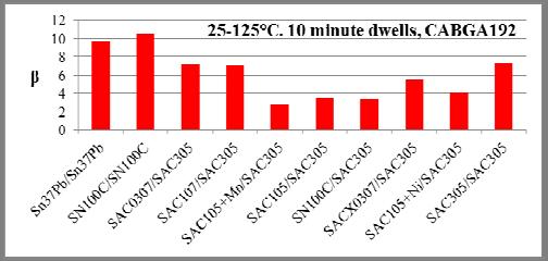
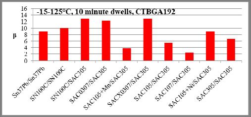
5 The Bi addition in the SACX0307 would be expected to go completely into solid solution in the Sn matrix although it might have some effect on the morphology of the intermetallic phases (Figure 8). Depending on the Cu content of the alloy, the intermetallic formed at the Ni/solder interface would probably be Ni 3 Sn 4 with Cu substituting for some of the Ni, or Cu 6 Sn 5 with Ni substituting for some of the Cu. Certainly the morphology of the intermetallic at the solder/ni interface is different from that at the solder/cu interface (Figures 10 & 11). Figure 8. SACX0307/Cu Interface Figure 10. SN100C/Ni Interface Mn has low solubility in the Sn matrix and is probably present in the microstructure in the form of a MnSn 2 intermetallic [6]. EDX would be needed to determine whether the darker particles in Figure 9 are that intermetallic phase or are related to the trace addition of Ce. Figure 11. SACX0307/Ni Interface THERMAL CYLING The thermal cycling methodology, including failure definition for in situ daisy-chain resistance measurement is described in Part I [1]. Figure 9. SAC105+Mn In addition to the fact that the solidification of the solder joints tested in this project occurred under conditions that were probably far from equilibrium, there is the additional complication of reactions between the solder and the Cu substrate of the PCB and the Ni metallization of the component to form layers of interfacial intermetallic. In the alloys containing Ni, the intermetallic compound formed at the Cu/solder interface would be the stabilized hexagonal close-packed crystal (Cu,Ni) 6 Sn 5 (Figure 4). In the alloys that do not contain Ni, (Figure 7) the intermetallic at the Cu/solder interface would probably be metastable hexagonal Cu 6 Sn 5 in the as-soldered condition, but this would be expected to undergo transformation to the equilibrium monoclinic form during thermal cycling [7]. One of the objectives of the subsequent failure analysis will be to determine whether the interfacial intermetallic compounds and their potential solid state phase transformations have any effect on the performance of the solder joints in this test program. At the time this paper was being written, complete results were available for the thermal cycling profiles listed in Table 3. Table 3. Available Thermal Cycle Data. Temperature Range Dwell (min) ΔT 0 C 100 C C -40 C 125 C C 25 C 125 C C -40 C 100 C C -15 C 125 C C RESULTS AND DISCUSSION In this paper, the focus is on the low-ag alloys and the single solder sphere/solder paste combination that is Agfree. Results for the characteristic life (η) for each alloy combination in each of the thermal cycle regimes is summarized in Figures 12-16, with the results in each case ranked from shortest to longest. Because, for the several reasons discussed elsewhere in this paper, the component 363
, has implications for the failure behavior and each plot of η is")


6 size had a significant effect on the ranking, the results for each component are presented separately. While the characteristic life is the first criterion by which the performance of an alloy is assessed, the shape parameter, (β), has implications for the failure behavior and each plot of η is accompanied by a plot of β values in the order of the ranking in the matching plot. A high β value means that once failure has begun all joints fail quickly, which can be considered desirable provided the associated η is large enough to provide the required service life. A low β indicates that failures are spread over a wide range, which is not a disadvantage provided that the early failures occur late enough to deliver the required service life. Although for each condition there is sometimes a wide range of β values, there is no clear pattern in the ranking. An alloy that has a low β in one condition has a high β in another. At this stage there is not enough data available to determine whether that variability is a reflection of the intrinsic properties of the alloys or it is just the result of experimental factors. Perhaps not surprisingly, in 17 of the 20 conditions the range of characteristic life was book-ended by Sn-37Pb and SAC305 with the characteristic life generally increasing with the Ag content. It is interesting to note, however, that in two conditions, the CTBGA84 in the C (Figure 13(a)) and C (Figure 14(a)) thermal cycles the SAC105+Ni performed similar to the SAC305, in the latter case even outperformed it by a slight margin. The SAC105+Ni alloy also performs almost as well as SAC305 in several other cases as is apparent in Figures 12 to 16. We continue to investigate the reason for this finding. The fact that in most cases the low-ag alloys outperformed Sn-37Pb by a signficant margin, and in several cases came close to matching the SAC305, could be taken as evidence that this category of alloys may provide a viable option as alternative Pb-free solders in applications where other properties, such as their higher melting points, would not be a problem. (a) (b) (c) (d) Figure 12. Ranked Characteristic Life for C Thermal Cycle with 10 Minute Dwells 364
 (c) Figure 13.")


 (d)")

7 (a) (a) \ (b) (b) (c) (c) Figure 13. Ranked Characteristic Life for C Thermal Cycle with 10 Minute Dwells (d) (d) Figure 14. Ranked Characteristic Life for C Thermal Cycle with 10 Minute Dwells 365
 Figure 15.")

")

8 (a) (a) (b) (b) (c) (c) Figure 15. Ranked Characteristic Life for C Thermal Cycle with 10 Minute Dwells (d) Figure 16. Ranked Characteristic Life for C Thermal Cycle with 10 Minute Dwells (d) 366

. Trends in Characteristic Life for CABGA192 Figure 17.")
9 Although there is some variation in ranking with thermal cycle and component size, it appears that there is an underlying overall trend in the ranking of particular alloys over all test conditions, in most cases within a fairly narrow range. When the incidence of each alloy occurring at a particular ranking is plotted, the trend that emerges is shown in Figure 17 with increasing Ag content in the solder joint tending to increase its ranking. Figure 18(b). Trends in Characteristic Life for CABGA192 Figure 17. Conditions Distribution of Ranking Over All Test When the characteristic life is plotted as a function of thermal cycle (Figures 18(a) & (b)) it can be seen that, as the intensity of the stress imposed on the joints in terms of strain and temperature increases, differences between the alloys diminish and it appears that all alloys are trending towards the characteristic life of Sn-37Pb, which remains remarkably stable over this range of conditions. Whether this is a consistent trend should become apparent when the results of thermal cycling with 60 and 120 minute dwells, which are also part of this DoE, become available. Effect of Component Type For the C thermal cycle the characteristic life of the joints of the CABGA192 was less than those of the CTBGA84 components by a factor of around 1.5. (Figure 19). The SN100C/SAC305 combination appears to be more sensitive to the increased severity of the conditions imposed by the larger package with its characteristic life in this thermal cycle reduced by a factor of more than 2, but the large difference in the Ag content of the joints for these two packages (Table 2) is probably the greatest contributor to this difference. Some critical properties of the SN100C alloy have been shown to be very sensitive to Ag additions in this range [3]. For all alloys the difference in performance between the packages results from the differences in the effective strain associated with the larger distance to the neutral point for the CABGA192 compared with the CTBGA84. Additionally the solder ball sizes on these packages are different; 0.46mm diameter for the CABGA192 compared to 0.30mm diameter for the CTBGA84. This solder ball size results in different BGA standoff heights, different solder joint crack areas, and different final solder alloy compositions. The dependence of the final joint compositions resulting from differences in sphere size is shown in Table 2. The different solder ball size might also have a small effect on the solder joint morphology and microstructure. Figure 18(a). Trends in Characteristic Life for CTBGA84 Figure 19. Effect of Component Type 367


10 Acceleration Factors The acceleration factors between the C profile and the C (Figure 20(a)) are generally in the range of 3-4 for most of the alloys, although those for SN100C/SN100C, SAC0307/SAC305 and SAC105/SAC305 lie in the 4-5 range. It is worth noting that in this comparison, the most extreme in this study, the Sn-37Pb is least affected with an acceleration factor of around 2. The lower sensitivity of η to cycling conditions of Sn-37Pb is consistent with the general observation that it is a relatively compliant alloy, accommodating substantial strain without work hardening and able to recover at the higher temperature end of the cycle. This finding is also consistent with earlier results of Henshall et al. [8, 9]. Figure 20(c). Thermal Cycle Acceleration Factors (c) The acceleration factor associated with an increase in peak temperature of 25 C for a thermal cycle with a ΔT of 100 C (Figure 20(b)) is generally in the range with the largest factor of more than 1.9 being for the combination of the SAC107 alloy with the CABGA192. This trend for the SAC107 alloy continues with the acceleration factor associated with an increase in peak temperature of 25 C for a thermal cycle with a ΔT of 140 C (Figure 20(c)). (a) In Table 4, the average acceleration factors for a selection of combinations of conditions over all the alloys in this low- Ag category are summarized with the standard deviation providing an indication of the alloy to alloy variation. Table 4. Acceleration Factor Summary for All Low-Ag Alloys CABGA192 component Thermal Cycle C C C Acceleration Factor C C C C Average Std Dev Average 2.62 Std Dev 0.36 Average 1.03 Std Dev 0.13 Weibull Analysis Since there are more combinations of alloy and test conditions than can be considered in detail in this paper, a selection of the results will be reviewed on the basis of what insights they might provide into some of the key issues arising from the trends in solder alloy development mentioned earlier. Since the effect of Ag on the performance of Pb-free solders in thermal cycling is the key issue in this part of the project, results will be considered on the basis of the Ag level of the alloy. For this purpose the alloys have been classified into the four general categories in Table 5. (b) Figure 20(a) (b). Thermal Cycle Acceleration Factors Table 5. Alloy Categories Used in Analysis of Results Category Alloy Paste No-Ag SN100C SN100C Very low-ag SAC0307, SN100C SAC305 Low-Ag SAC105, SAC107 SAC305 Micro-Alloyed SACX0307, SAC105+Ni, SAC105+Mn SAC305 Of the three major microalloying additions, Ni, Mn and Bi, only Ni was present in alloys with more than one Ag content and so the trend analysis is based on that addition. The microalloying additions differ in the way that they change behavior and properties of the alloy. Ni works by 368
![incorporating selectively in the Cu 6 Sn 5 intermetallic phase and changing its behavior in several ways [3, 5, 7].](/docs-images/76/74490521/images/11-0.jpg "On the basis of the binary Sn-Bi phase diagram, Bi has considerable solubility in Sn and at the low level of its addition in the SACX0307 alloy its solubility is unlikely to be affected by other")

11 incorporating selectively in the Cu 6 Sn 5 intermetallic phase and changing its behavior in several ways [3, 5, 7]. On the basis of the binary Sn-Bi phase diagram, Bi has considerable solubility in Sn and at the low level of its addition in the SACX0307 alloy its solubility is unlikely to be affected by other elements present, so it could be assumed that it provides some solid solution strengthening of the Sn matrix. The way in which the Mn and Ce additions work in the SAC105 alloy is discussed in reference 6. Because strain is the key driver for solder joint deterioration, the focus will be on the results for the CABGA192, which, for a given temperature cycle, imposes more strain on the peripheral joints. The oversized die further increases the strain to which the solder is subjected for a given difference in thermal expansion between the component package and the PCB. Most of the results reported will be for the C thermal cycle, which is commonly used when testing circuitry operated in relatively benign controlled environments. The effect of a more extreme cycle will be examined by comparison with results for the C cycle, which, for the purposes of this project is considered to be representative of the conditions to which circuitry operating in uncontrolled environments could be exposed. The effect of peak temperature will be examined by comparison of results for the C and C profiles. Figure 21. Weibull Plots for CABGA192, Thermal Cycle C, 10 minute Dwells Comparing the Ag-free Alloy with Reference Alloys Figure 22 presents the effect of Ag on the Sn-0.7Cu alloy. The zero-ag alloy in this DoE (SN100C) also contains 0.05% Ni but it is unlikely that this would have a major effect on performance in this type of test. The proven effects of the Ni addition are in promoting eutectic behavior in solidification and stabilizing the hexagonal close packed form of the Cu 6 Sn 5 intermetallic [7]. Any effect from the Ni would probably result from the elimination of primary tin dendrites and the associated shrinkage defects that tend to occur in the basic Sn-0.7Cu alloy and the benefits of the resulting fine uniform eutectic structure [5]. Effect of Composition Figure 21 clearly shows the dramatic increase in cycles to failure between SAC305 and Sn-37Pb for the C profile. For the conditions tested, the characteristic life of SAC305 is nearly four times that of Sn-37Pb. As noted in Part I [1], there were early concerns that low-ag, Pb-free alloys might perform worse in thermal cycling than Sn- 37Pb. Consistent with recent studies [8-10], this is not the case for the C profile tested here. This result is most dramatically demonstrated by the data for the Ag-free SN100C/SN100C results shown in Figure 21. Even with no Ag present, the Pb-free alloys out-perform Sn-37Pb for these testing conditions. Figure 21 also shows that the presence of a calculated 0.29% Ag in the SN100C joints reflowed with SAC305 had no significant effect on the performance of the SN100C in this test condition. Since the 10 minute dwell used in the thermal cycling reported here is not representative of real service conditions, these differences between the alloys cannot necessarily be taken as an indication of their relative performance in practical application. It is expected that the results from thermal cycling with longer dwell times that were also included in the DoE, of which the work reported here is a part, will provide a better indication of performance in actual service conditions. Figure 22. Weibull Plots for CABGA192, Thermal Cycle C, 10 minute Dwells Showing the Effect of Ag Levels on Sn-0.7Cu The increase in the Ag content from zero to a calculated 0.54% in the SAC0307 alloy had little effect on the β but increased η by 31%. The increase to a calculated 1.19% Ag in the SAC107 alloy increased η by 61% compared with the Ag-free joint, but the variation in the results increased, with a first failure occurring before the first failure of the 369


12 SAC0307 and a reduction in β from around 9 for SN100C and SAC0307 to around 5. As noted earlier, it is not clear at this time whether this change in β is related to the alloy composition or an artifact of the experiment. In Figure 23 it is clear that, in terms of an increase in survival in these conditions compared with Sn-37Pb, even the calculated 0.54% Ag in the SAC0307 delivered 61% improvement as compared to the η achieved with SAC305. The calculated 1.19% Ag in the SAC107 delivered 83% of the SAC305 improvement, but at the expense of a wider spread of results mentioned earlier. Figure 24. Weibull Plots of CABGA192, Thermal Cycle C, 10 minute Dwells Showing the Effect of the Indicated Microalloying Additions The microalloying additions in the proprietary alloy SACX0307 do not appear to have any statistically significant effect (Figure 25). Figure 23. Weibull Plots for CABGA192, Thermal Cycle C, 10 minute Dwells Comparing Low-Ag Alloys with Reference Alloys The results in Figure 24 indicate that the Ni addition to the SAC105 alloy had no significant effect on β or η in this test. This is not unexpected since the main reason that Ni is added to this alloy is because of its beneficial effect on performance in impact loading and there is no reason to expect a significant effect in relatively mild thermal cycling. Similar, earlier findings of Henshall et al [8] did not reveal a dramatic effect of a Ni dopant on thermal fatigue performance. The Mn addition reduced η by about 30% with a wider variation in results (smaller ρ) that suggests more than one failure mechanism. Figure 25. Weibull Plots of CABGA192, Thermal Cycle C, 10 minute Dwells Comparing the Effect of Microalloying Additions, Bi and Rare Earth Elements It is clear from Figure 26 that in this test the increase in Cu content from a nominal 0.5% to 0.7% had no significant effect on the performance of the 1% Ag alloy. 370


13 Figure 26. Weibull Plots of CABGA192, Thermal Cycle C, 10 minute Dwells Comparing the Effect of Cu Level Figure 27. Weibull Plots Showing the Effect of Component Size on an Ag-free Alloy in Thermal Cycling C, 10 Minute Dwells Effects of Component Size For all alloys the additional strain on the outer joints resulting from the larger component size significantly reduces η (Figures 27-30). The results of this comparison are summarized in Table 6. The effect of the larger component size appears to be significantly less in terms of reduction in η for SAC0307 and SAC105 than the microalloyed SN100C and SACX0307. The greatest effect appears to have occurred in the SN100C reflowed with SAC305 with the effect on the Ag-free SN100C similar to that on the SACX0307. Further experimentation and analysis are required to determine whether these trends hold in general. As mentioned previously in interpreting these results, account has to be taken of the sensitivity of the final joint composition to the solder ball size (Table 2). For a nominally identical composition there is a difference in component size and ball size as well as a difference in the Ag level in the joints of the CTBGA84 and the CABGA192. Figure 28. Weibull Plots Showing the Effect of Component Size on a Very Low-Ag Alloy in Thermal Cycling C, 10 Minute Dwells Figure 29. Weibull Plots Showing the Effect of Component Size on a Microalloyed Very Low-Ag Alloy in Thermal Cycling C, 10 Minute Dwells 371


14 Figure 30. Weibull Plots Showing the Effect of Component Size on a Low-Ag Alloy in Thermal Cycling C, 10 Minute Dwells Figure 31. Weibull Plots Showing the Effect of Thermal Cycle on an Ag-free Alloy Joints to CABGA192 Component Table 6. Summary of Component Effect on Characteristic Life Category Alloy/Paste 0/100/10 0/100/10 η CABGA192 CTBGA84 Ratio η β η Β Reference Sn-37Pb/Sn-37Pb Alloys SAC305/SAC No Ag SN100C/SN100C Very Low Ag SN100C/SAC SAC0307/SAC Low Ag SAC105/SAC SAC107/SAC Microalloyed SACX0307/SAC SAC105+Ni/SAC SAC105+Mn/SAC Effect of Thermal Cycle Range The effect of a more extreme thermal cycle is apparent in Figures 31-35, which compare Weibull plots for the thermal cycle C with those for C, in both cases with 10 minute dwells. These results are summarized in Table 7. Figure 32. Weibull Plots Showing the Effect of Thermal Cycle on Very Low-Ag Alloy Joints to CABGA192 Component While in all cases there was a substantial drop with an increase in thermal cycle range, it appears that the Ag-free SN100C and the SAC105 suffered the greatest drop with an η for the more extreme thermal cycle about 40% of that of the milder cycle with SAC0307 and SAC107 suffering only a little less reduction. The differences between other alloys seem to be within the range of experimental error. Figure 33. Weibull Plots Showing the Effect of Thermal Cycle on Microalloyed Very Low-Ag Alloy Joints to CABGA192 Component 372


15 Figure 34. Weibull Plots Showing the Effect of Thermal Cycle on Low-Ag Alloy Joints to CABGA192 Component Figure 36. Weibull Plots Showing the Effect of Peak Thermal Cycle Temperature on Ag-free Alloy Joints to CABGA192 Components Figure 35. Weibull Plots Showing the Effect of Thermal Cycle on Ni-doped Low-Ag Alloy Joints to CABGA192 Components Figure 37. Weibull Plots Showing the Effect of Peak Thermal Cycle Temperature on Very Low-Ag Alloy Joints to CABGA192 Component Table 7. Summary of Effect of Temperature Range 0/100/10 CABGA192-40/125/10 CABGA192 Acceleration Factor 0/100/10 to -40/125/10 Category Alloy/Paste η β η β Reference Sn-37Pb/Sn-37Pb Alloys SAC305/SAC No Ag SN100C/SN100C Very SN100C/SAC Low Ag SAC0307/SAC Low Ag SAC105/SAC SAC107/SAC SACX0307/SAC SAC105+Ni/SAC Microalloyed SAC105+Mn/SAC Effect of Peak Thermal Cycle Temperature The effect of a 25 C higher peak temperature on thermal cycles with a ΔT of 100 C is presented in Figures The results are summarized in Table 8. The SN100C reflowed with SAC305 was least affected by the higher peak temperature with the SAC107 experiencing the greatest loss. Figure 38. Weibull Plots Showing the Effect of Peak Thermal Cycle Temperature on Microalloyed Very Low-Ag Alloy Joints to CABGA192 Component 373
16 failure analysis are available, it will not be possible to get a real insight into how performance is related to composition. Nevertheless, trends such as those that are apparent in Figure 17 indicate that, in short dwell thermal cycles there is a correlation between characteristic life and Ag content. Another key finding is that all the Pb-free alloys perform better than Sn-37Pb under the conditions tested, including the Ag-free SN100C/SN100C combination. This together with the fact that all the Pb-free alloys have high acceleration factors (0-100 C vs C) suggests that low-ag alloys will perform better than Sn-37Pb in office or similarly controlled environments. This finding supports the earlier work of Henshall et al. [8,9]. Figure 39. Weibull Plots Showing the Effect of Peak Thermal Cycle Temperature on Low-Ag Alloy on CABGA192 Component One of the most interesting trends that emerge from this study is apparent in Figure 18. That is that as the stress generated by strain and exposure to elevated temperature increases, the difference between the Pb-free solder alloys collapses and their performance appears to be converging towards that of Sn-37Pb. The results of thermal cycling with longer dwells included in the DoE, of which the testing reported here is a part, will confirm whether that trend to convergence as the severity of conditions increase will continue. Given that both Sn-37Pb and Pb-free solders have what is essentially a Sn matrix, this convergence is a trend that might be expected. While the intermetallic precipitates formed by the Cu, and in particular the Ag, have an initial strengthening effect when they are small, finely dispersed and possibly to some extent coherent with the tin matrix, that effect will inevitably diminish as short range order at their interface with the tin breaks down and the particles coarsen. Figure 40. Weibull Plots Showing the Effect of Peak Thermal Cycle Temperature on Ni-doped Low-Ag Alloy Joints to CABGA192 Component. Table 8. Summary of Effect of Peak Temperature 0/100/10 CABGA192 25/125/10 CABGA192 Acceleration Factor 0/100/10 to 25/125/10 Category Alloy/Paste η β η β Reference Sn-37Pb/Sn-37Pb Alloys SAC305/SAC No Ag SN100C/SN100C Very SN100C/SAC Low Ag SAC0307/SAC Low Ag SAC105/SAC SAC107/SAC SACX0307/SAC SAC105+Ni/SAC Microalloyed SAC105+Mn/SAC CONCLUSIONS This project has generated a very large amount of data and at this early stage in the analysis we can only note the general trends. The challenging point that emerges is that the relationships between solder alloy composition and performance are complex. While the results reported here make it possible to make some general observations, until the results of the full set of thermal cycle data and the Although reference to this point has been made throughout this paper, it has to be emphasized that because SAC305 paste was used for the reflow of all alloys except SN100C and the reference alloy Sn-37Pb, the composition of the solder joints was significantly different from the nominal composition of the solder ball alloy. And because of ball size effects there were significant differences in the composition of the joints between the two component types. This has introduced an additional complication into the interpretation of the results. FUTURE WORK Obviously, the first of the future work will include completion of thermal cycling for all alloys and profiles [1]. Beyond that the objective of this project extends to the possibility of establishing criteria for alloy selection and perhaps providing a basis for fine tuning formulations to achieve improved performance. To provide a basis for alloy improvement, it is necessary to understand the relationship between the alloy composition, the microstructure of the assoldered joint, and the evolution of the microstructure to failure. To achieve that understanding there will have to be detailed failure analyses which will be another significant step in this program. 374
17 ACKNOWLEDGEMENTS This paper is the third in a series of four papers prepared to report the results of the inemi Pb-Free Alloy Characterization Project as of mid Many people have contributed to the project and to these papers and in addition to the acknowledgements in the other papers in this series (References 1, 11 and 12), the first two authors listed on this paper would like to acknowledge the valuable contributions to the interpretation of the results and the refining of the text made by Elizabeth Benedetto, Richard Coyle, Richard Parker, Joseph Smetana and Jasbir Bath. Report: Part IV - Effect of Isothermal Preconditioning on Thermal Fatigue Life, Proceedings of SMTAI 2012, Orlando, FL, October REFERENCES [1] G. Henshall et al., inemi Pb-Free Alloy Characterization Project Report: Part I Program Goals, Experimental Structure, Alloy Characterization, and Test Protocols for Accelerated Temperature Cycling, Proceedings of SMTAI 2012, Orlando, FL, October [2] J. Pan, Lead-Free Liquidus Temperature Calculator, (2008) [3] T. Ventura, C.M. Gourlay, K. Nogita, T. Nishimura, M. Rappaz, A.K. Dahle, "The influence of wt.% Ni on the microstructure and fluidity length of Sn-0.7wt%Cu-xNi", Journal of Electronic Materials, 37, 1 (2008) [4] K.-W. Moon, W.J. Boettinger, U.R. Kattner, F.S. Biancaniello, and C.A. Handwerker, J. Elec. Mater. Vol. 29, (2000), p [5] K. Nogita, J. Read, T. Nishimura, K. Sweatman, S. Suenaga and A. K. Dahle, "Microstructure control in Sn- 0.7mass%Cu alloys", Materials Transactions, Vol. 46, No. 11 (2005) [6] W. Liu, N.-C. Lee, A. Porras, M. Ding, A. Gallagher, A. Huang, S. Chen, J. Lee, Achieving high reliability low cost lead-free SAC solder joints via Mn or Ce doping, SMTA Journal, vol. 22, No. 4, 2009, [7] K. Nogita and T. Nishimura, Nickel stabilized hexagonal (Cu,Ni) 6 Sn 5 in Sn-Cu-Ni lead-free solder alloys, Scripta Materialia, 59 (2008) [8] G. Henshall, et al., Low-Silver BGA Assembly, Phase II Reliability Assessment. Sixth Report: Thermal Cycling Results for Unmixed Joints, Proceedings SMTAI, p. 595 (2010) [9] G. Henshall, et al., Low-Silver BGA Assembly, Phase II Reliability Assessment. Seventh Report: Mixed Metallurgy Solder Joint Thermal Cycling Results, Proc. APEX, p. S32-03 (2011). [10] R. Coyle, H. McCormick, J. Osenbach, P. Read, R. Popowich, D. Fleming, and J. Manock, Pb-free Alloy Silver Content and Thermal Fatigue Reliability of a Large Plastic Ball Grid Array (PBGA) Package, Journal of SMT, Vol. 24, Issue 1, 27-33, January-March [11] R. Parker, R. Coyle, G. Henshall, J. Smetana, E. Benedetto, inemi Pb-Free Alloy Characterization Project Report: Part II - Thermal Fatigue Results for Two Common Temperature Cycles, Proceedings of SMTAI 2012, Orlando, FL, October [12] R. Coyle, R. Parker, G. Henshall, M. Osterman, J. Smetana, E. Benedetto, D. Moore, G. Chang, J. Arnold, and T-K Lee, inemi Pb-Free Alloy Characterization Project 375
THE EFFECTS OF PHOSPHORUS IN LEAD-FREE SOLDERS
 As originally published in the SMTA Proceedings. THE EFFECTS OF PHOSPHORUS IN LEAD-FREE SOLDERS Keith Sweatman, Takatoshi Nishimura and Takuro Fukami Nihon Superior Co., Ltd Osaka, Japan k.sweatman@nihonsuperior.co.jp
Composition/wt% Bal SA2 (SABI) Bal SA3 (SABI + Cu) Bal
 Bal SA3 (SABI + Cu) Bal") Improving Thermal Cycle and Mechanical Drop Impact Resistance of a Lead-free Tin-Silver-Bismuth-Indium Solder Alloy with Minor Doping of Copper Additive Takehiro Wada 1, Seiji Tsuchiya 1, Shantanu Joshi
Improving Thermal Cycle and Mechanical Drop Impact Resistance of a Lead-free Tin-Silver-Bismuth-Indium Solder Alloy with Minor Doping of Copper Additive Takehiro Wada 1, Seiji Tsuchiya 1, Shantanu Joshi
DEVELOPMENT OF LEAD-FREE ALLOYS WITH ULTRA-HIGH THERMO- MECHANICAL RELIABILITY
 As originally published in the SMTA Proceedings. DEVELOPMENT OF LEAD-FREE ALLOYS WITH ULTRA-HIGH THERMO- MECHANICAL RELIABILITY Pritha Choudhury, Ph.D., Morgana Ribas, Ph.D., Ranjit Pandher, Ph.D., Anil
THE EFFECT OF VACUUM REFLOW PROCESSING ON SOLDER JOINT VOIDING AND THERMAL FATIGUE RELIABILITY
 THE EFFECT OF VACUUM REFLOW PROCESSING ON SOLDER JOINT VOIDING AND THERMAL FATIGUE RELIABILITY Richard Coyle 1, Dave Hillman 2, Michael Barnes 3, David Heller 3, Charmaine Johnson 1, Richard Popowich 1,
inemi Pb-FREE ALLOY CHARACTERIZATION PROJECT REPORT: PART IV - EFFECT OF ISOTHERMAL PRECONDITIONING ON THERMAL FATIGUE LIFE
 inemi Pb-FREE ALLOY CHARACTERIZATION PROJECT REPORT: PART IV - EFFECT OF ISOTHERMAL PRECONDITIONING ON THERMAL FATIGUE LIFE Richard Coyle 1, 2, Gregory Henshall 3, Michael Osterman 4, Joe Smetana 5 Elizabeth
The Morphology Evolution and Voiding of Solder Joints on QFN Central Pads with a Ni/Au Finish
 The Morphology Evolution and Voiding of Solder Joints on QFN Central Pads with a Ni/Au Finish Julie Silk 1, Jianbiao Pan 2, Mike Powers 1 1 Agilent Technologies, 1400 Fountaingrove Parkway, Santa Rosa,
COMPONENT LEVEL RELIABILITY FOR HIGH TEMPERATURE POWER COMPUTING WITH SAC305 AND ALTERNATIVE HIGH RELIABILITY SOLDERS
 As originally published in the SMTA Proceedings. COMPONENT LEVEL RELIABILITY FOR HIGH TEMPERATURE POWER COMPUTING WITH SAC305 AND ALTERNATIVE HIGH RELIABILITY SOLDERS Thomas Sanders, Sivasubramanian Thirugnanasambandam
Balver Zinn Josef Jost GmbH & Co. KG SN100C : Micro alloyed lead free solder The Nickel effects
 Paolo Corviseri / Balver Zinn Techn. Department Certified IPC-A-610 Trainer (CIT) Paolo.corviseri@balverzinn.com Phone: +49 2375 1 915150 Mobil: +49 170 6379549 Balver Zinn Josef Jost GmbH & Co. KG SN100C
Sample Preparation for Mitigating Tin Whiskers in alternative Lead-Free Alloys
 As originally published in the IPC APEX EXPO Conference Proceedings. Sample Preparation for Mitigating Tin Whiskers in alternative Lead-Free Alloys Mehran Maalekian Karl Seelig, V.P. Technology Timothy
System Level Effects on Solder Joint Reliability
 System Level Effects on Solder Joint Reliability Maxim Serebreni 2004 2010 Outline Thermo-mechanical Fatigue of solder interconnects Shear and tensile effects on Solder Fatigue Effect of Glass Style on
Reflow Profiling: Time a bove Liquidus
 Reflow Profiling: Time a bove Liquidus AIM/David Suraski Despite much research and discussion on the subject of reflow profiling, many questions and a good deal of confusion still exist. What is clear
Impact of Intermetallic Growth on the Mechanical Strength of Pb-Free BGA Assemblies
 Impact of Intermetallic Growth on the Mechanical Strength of Pb-Free BGA Assemblies Patrick Roubaud, Grace Ng, Greg Henshall Hewlett Packard Ronald Bulwith, Robert Herber - Alpha Metals Swaminath Prasad,
The Effect of Cu and Ni on the Structure and Properties of the IMC Formed by the Reaction of Liquid Sn-Cu Based Solders with Cu Substrate
 WDS'08 Proceedings of Contributed Papers, Part III, 220 224, 2008. ISBN 978-80-7378-067-8 MATFYZPRESS The Effect of Cu and Ni on the Structure and Properties of the IMC Formed by the Reaction of Liquid
LEAD FREE ALLOY DEVELOPMENT
 LEAD FREE ALLOY DEVELOPMENT Karl F. Seelig, VP of Technology AIM Cranston, RI. USA. kseelig@aimsolder.com Abstract. When lead-free solders were first introduced to the electronics industry in the early
Material Selection and Parameter Optimization for Reliable TMV Pop Assembly
 Selection and Parameter Optimization for Reliable TMV Pop Assembly Brian Roggeman, David Vicari Universal Instruments Corp. Binghamton, NY, USA Roggeman@uic.com Martin Anselm, Ph.D. - S09_02.doc Lee Smith,
Low/No Silver Alloy Solder Paste
 Low/No Silver Alloy Solder Paste Definition Stage : Phase 1 Process Feasibility Study Project Leader: Jennifer Nguyen, Flextronics Project Facilitator: John Davignon HDP User Group Member Meeting Feb 26,
The Relationship between Backward Compatible Assembly and Microstructure on the Thermal Fatigue Reliability of an Extremely Large Ball Grid Array
 The Relationship between Backward Compatible Assembly and Microstructure on the Thermal Fatigue Reliability of an Extremely Large Ball Grid Array Richard Coyle, Richard Popowich, Peter Read, and Debra
Low Temperature Lead-Free Production Versus SAC
 Low Temperature Lead-Free Production Versus SAC Designing a product that has minimal environmental impact for its entire life cycle is very demanding and a real challenge for designers and manufacturers.
SN100C Technical Guide
 SN100C Technical Guide INTRODUCTION SN100C is a lead-free tin/copper//germanium alloy. It has been in use since about the year 2000. Since then SN100C has become a world leading alloy in wave and selective
Effects of SAC Alloy Copper Dissolution Rates on PTH Processes: Cost and performance justify use of certain alternatives to SAC305/405
 Effects of SAC Alloy Copper Dissolution Rates on PTH Processes: Cost and performance justify use of certain alternatives to SAC305/405 1 Craig Hamilton, Polina Snugovsky (Celestica) & Matthew Kelly (IBM)
Statement of Work (SOW) inemi Board Assembly TIG BiSn-Based Low-Temperature Soldering Process and Reliability Project
 inemi Board Assembly TIG BiSn-Based Low-Temperature Soldering Process and Reliability Project") Statement of Work (SOW) inemi Board Assembly TIG BiSn-Based Low-Temperature Soldering Process and Reliability Project Version 1.4 Date: December 1, 2015 Project Leader: Raiyo Aspandiar, Intel Corporation
Statement of Work (SOW) inemi Board Assembly TIG BiSn-Based Low-Temperature Soldering Process and Reliability Project Version 1.4 Date: December 1, 2015 Project Leader: Raiyo Aspandiar, Intel Corporation
IMPACT OF MICROVIA-IN-PAD DESIGN ON VOID FORMATION
 IMPACT OF MICROVIA-IN-PAD DESIGN ON VOID FORMATION Frank Grano, Felix Bruno Huntsville, AL Dana Korf, Eamon O Keeffe San Jose, CA Cheryl Kelley Salem, NH Joint Paper by Sanmina-SCI Corporation EMS, GTS
IMPACT OF COMPONENT TERMINAL FINISH ON THE RELIABILITY OF Pb-FREE SOLDER JOINTS
 IMPACT OF COMPONENT TERMINAL FINISH ON THE RELIABILITY OF Pb-FREE SOLDER JOINTS Gregory Henshall, Patrick Roubaud, Geary Chew Hewlett-Packard Co. Palo Alto, California greg_henshall@hp.com Swaminath Prasad,
Lead-Free Solder Bump Technologies for Flip-Chip Packaging Applications
 Lead-Free Solder Bump Technologies for Flip-Chip Packaging Applications Zaheed S. Karim 1 and Jim Martin 2 1 Advanced Interconnect Technology Ltd. 1901 Sunley Centre, 9 Wing Yin Street, Tsuen Wan, Hong
Effects of Bi Content on Mechanical Properties and Bump Interconnection Reliability of Sn-Ag Solder Alloys
 Effects of Bi Content on Mechanical Properties and Bump Interconnection Reliability of Sn-Ag Solder Kazuki Tateyama, Hiroshi Ubukata*, Yoji Yamaoka*, Kuniaki Takahashi*, Hiroshi Yamada** and Masayuki Saito
Thermo-Mechanical FEM Analysis of Lead Free and Lead Containing Solder for Flip Chip Applications
 Thermo-Mechanical FEM Analysis of Lead Free and Lead Containing Solder for Flip Chip Applications M. Gonzalez 1, B. Vandevelde 1, Jan Vanfleteren 2 and D. Manessis 3 1 IMEC, Kapeldreef 75, 3001, Leuven,
Sample Preparation for Mitigating Tin Whiskers in alternative Lead-Free Alloys
 Sample Preparation for Mitigating Tin Whiskers in alternative Lead-Free Alloys Mehran Maalekian Karl Seelig, V.P. Technology Timothy O Neill, Technical Marketing Manager AIM Solder Cranston, RI Abstract
HALT Testing of Backward Soldered BGAs on a Military Product
 As originally published in the IPC APEX EXPO Conference Proceedings. HALT Testing of Backward Soldered BGAs on a Military Product B. Gumpert, B. Fox, L. Woody Lockheed Martin Ocala, FL Abstract The move
Manufacturing and Reliability Modelling
 Manufacturing and Reliability Modelling Silicon Chip C Bailey University of Greenwich London, England Printed Circuit Board Airflow Temperature Stress at end of Reflow Stress Product Performance in-service
Phase Diagrams of Pure Substances Predicts the stable phase as a function of P total and T. Example: water can exist in solid, liquid and vapor
 PHASE DIAGRAMS Phase a chemically and structurally homogenous region of a material. Region of uniform physical and chemical characteristics. Phase boundaries separate two distinct phases. A single phase
SOLDER JOINT RELIABILITY TEST SUMMARY
 Project Number: SJR Tracking Code: TC0623-SEAF-SJR-1059 Requested by: Jeremy Wooldridge Date: 05/20/2008 Product Rev: D (SEAF), C (SEAM) Part #: SEAF-50-5.0-S-10-2-A/ SEAM-50-2.0-S-10-2-A SEAF-50-6.5-S-10-1-A/
Validated Test Method to Characterize and Quantify Pad Cratering Under Bga Pads on Printed Circuit Boards
 Validated Test Method to Characterize and Quantify Pad Cratering Under Bga Pads on Printed Circuit Boards Mudasir Ahmad, Jennifer Burlingame, Cherif Guirguis Technology and Quality Group Cisco Systems,
A STUDY OF THE ENEPIG IMC FOR EUTECTIC AND LF SOLDERS
 A STUDY OF THE ENEPIG IMC FOR EUTECTIC AND LF SOLDERS G.Milad, D.Gudeczauskas, G.Obrien, A.Gruenwald Uyemura International Corporation Southington, CT ABSTRACT: The solder joint formed on an ENEPIG surface
Whisker free tin Jan Feb 2012-stripped:Metal Tech Speaking Template USE THIS.qxd 2/24/ :07 AM Page 1
 Whisker free tin Jan Feb 2012-stripped:Metal Tech Speaking Template USE THIS.qxd 2/24/2012 11:07 AM Page 1 BY GEORGE MILAD, NATIONAL ACCOUNTS MANAGER FOR TECHNOLOGY, UYEMURA USA, SOUTHINGTON, CONN. The
Metals I. Anne Mertens
 "MECA0139-1: Techniques "MECA0462-2 additives : et Materials 3D printing", Selection", ULg, 19/09/2017 25/10/2016 Metals I Anne Mertens Introduction Outline Metallic materials Materials Selection: case
BOARD LEVEL ASSEMBLY AND RELIABILITY CONSIDERATIONS FOR QFN TYPE PACKAGES
 BOARD LEVEL ASSEMBLY AND RELIABILITY CONSIDERATIONS FOR QFN TYPE PACKAGES Ahmer Syed and WonJoon Kang Amkor Technology, Inc. 1900 S. Price Road Chandler, Arizona ABSTRACT There is a strong interest in
Becoming Lead Free. Automotive Electronics. Antonio Aires Soldering Technical Specialist Visteon Corporation - Palmela Plant
 Automotive Electronics Becoming Lead Free Antonio Aires Soldering Technical Specialist Visteon Corporation - Palmela Plant 1 Agenda 1. Leadfree Electronics Drivers 2. Requirements 3. Areas of Impact 4.
Head-in-Pillow BGA Defects Karl Seelig AIM Cranston, Rhode Island, USA
 Head-in-Pillow BGA Defects Karl Seelig AIM Cranston, Rhode Island, USA Head-in-pillow (HiP), also known as ball-and-socket, is a solder joint defect where the solder paste deposit wets the pad, but does
EPOXY FLUX MATERIAL AND PROCESS FOR ENHANCING ELECTRICAL INTERCONNECTIONS
 As originally published in the SMTA Proceedings. EPOXY FLUX MATERIAL AND PROCESS FOR ENHANCING ELECTRICAL INTERCONNECTIONS Neil Poole, Ph.D., Elvira Vasquez, and Brian J. Toleno, Ph.D. Henkel Electronic
New Pb-Free Solder Alloy for Demanding Applications. Presented by Karl Seelig, VP Technology, AIM
 New Pb-Free Solder Alloy for Demanding Applications Presented by Karl Seelig, VP Technology, AIM Why REL? The evolution and expansion of electronics into more harsh operating environments performing more
WF6317. A superactive low-volatile/high heat-resistant water-soluble flux for ball soldering
 WF637 A superactive low-volatile/high heat-resistant water-soluble flux for ball soldering Low viscosity and high tacking power stabilize ball holding force and ensures excellent solder wettability Easy
Eliminating Wave Soldering with Low Melting Point Solder Paste ABSTRACT Process Cost Reduction INTRODUCTION
 Eliminating Wave Soldering with Low Melting Point Solder Paste Mitch Holtzer and Tuck Weng Mok Alpha, an Alent plc Company 109 Corporate Blvd., South Plainfield, NJ 07080 USA Email: mholtzer@alent.com;
3D-WLCSP Package Technology: Processing and Reliability Characterization
 3D-WLCSP Package Technology: Processing and Reliability Characterization, Paul N. Houston, Brian Lewis, Fei Xie, Ph.D., Zhaozhi Li, Ph.D.* ENGENT Inc. * Auburn University ENGENT, Inc. 2012 1 Outline Packaging
Effects of Flux and Reflow Parameters on Lead-Free Flip Chip Assembly. Sandeep Tonapi 1 Doctoral Candidate
 Effects of Flux and Reflow Parameters on Lead-Free Flip Chip Assembly Sandeep Tonapi 1 Doctoral Candidate Peter Borgesen, Ph.D. 2 Manager, Area Array Consortium K. Srihari, Ph.D. 1 Professor, Department
Lead-Free Connectors - An Overview
 Lead-Free Connectors - An Overview Pete Elmgren Molex Inc. 15 August 2003 Introduction For more than 50 years, lead-bearing solders have been used almost exclusively throughout the electronics industry
Reliability of Interconnects in LED Lighting Assemblies Utilizing Metal Clad Printed Circuit Boards Stefano Sciolè BDM I.M.S.
 Reliability of Interconnects in LED Lighting Assemblies Utilizing Metal Clad Printed Circuit Boards Stefano Sciolè BDM I.M.S. Henkel Electronic Materials Agenda 1. Introduction 2. Motivation 3. Interconnect
Mohammad Anwar Karim Id :
 Department of Mechanical and Industrial Engineering ME 8109 Casting and Solidification of Materials EFFECTS OF RAPID SOLIDIFICATION ON MICROSTRUCTURE AND PROPERTIES OF AL, MG & TI ALLOYS Winter 2012 Presented
Basic PCB Level Assembly Process Methodology for 3D Package-on-Package
 Basic PCB Level Assembly Process Methodology for 3D Package-on-Package Vern Solberg STC-Madison Madison, Wisconsin USA Abstract The motivation for developing higher density IC packaging continues to be
Controlling the Microstructures from the Gold-Tin Reaction
 Controlling the Microstructures from the Gold-Tin Reaction J. Y. Tsai, C. W. Chang, Y. C. Shieh, Y. C. Hu, and C. R. Kao* Department of Chemical & Materials Engineering National Central University Chungli
The role of minor modifying additives on soldering properties of Sn-Ag-Cu green solders
 Southern Cross University epublications@scu 23rd Australasian Conference on the Mechanics of Structures and Materials 2014 The role of minor modifying additives on soldering properties of Sn-Ag-Cu green
INTERFLUX ELECTRONICS NV
 Reflow soldering temperature profiling Min : 30sec Max : 120sec Max : +4 C/sec Max : 250 C Min : 230 C Min: +0,5 C/sec Min : +1 C/sec Max : +3 C/sec Max : +1 C/sec Max : -6 C/sec Min : -2 C/sec Min : +1
Influence of Thermal Cycling on the Microstructure and Shear Strength of Sn3.5Ag0.75Cu and Sn63Pb37 Solder Joints on Au/Ni Metallization
 68 J. Mater. Sci. Technol., Vol.23 No.1, 2007 Influence of Thermal Cycling on the Microstructure and Shear Strength of Sn3.5Ag0.75Cu and Sn63Pb37 Solder Joints on Au/Ni Metallization Hongtao CHEN 1,2),
A New Approach for Early Detection of PCB Pad Cratering Failures
 A New Approach for Early Detection of PCB Pad Cratering Failures Anurag Bansal, Gnyaneshwar Ramakrishna and Kuo-Chuan Liu Cisco Systems, Inc., San Jose, CA anurbans@cisco.com Abstract Pad cratering refers
Advanced Analytical Techniques for Semiconductor Assembly Materials and Processes. Jason Chou and Sze Pei Lim Indium Corporation
 Advanced Analytical Techniques for Semiconductor Assembly Materials and Processes Jason Chou and Sze Pei Lim Indium Corporation Agenda Company introduction Semiconductor assembly roadmap challenges Fine
Ultralow Residue Semiconductor Grade Fluxes for Copper Pillar Flip-Chip
 Ultralow Residue Semiconductor Grade Fluxes for Copper Pillar Flip-Chip SzePei Lim (Presenter), Jason Chou, Maria Durham, and Dr. Andy Mackie Indium Corporation 1 Outline of Presentation Roadmaps and challenges
Welcome to the Real World of Lead Free Soldering
 Welcome to the Real World of Lead Free Soldering Metallic Resources, Inc. Howard Stevens Nimal Liyanage,, Ph.D Objective: to Provide Education Regarding the Effects of Various Lead Free Soldering Alloys
SCV Chapter, CPMT Society, IEEE September 14, Voids at Cu / Solder Interface and Their Effects on Solder Joint Reliability
 Voids at / Solder Interface and Their Effects on Solder Joint Reliability Zequn Mei, Mudasir Ahmad, Mason Hu, Gnyaneshwar Ramakrishna Manufacturing Technology Group Cisco Systems, Inc. Acknowledgement:
The Effect of Voiding in Solder Interconnections Formed from Lead Free Solder Pastes with Alloys of Tin, Silver and Copper
 SOLDER PRODUCTS VALUE COUNCIL ASSOCIATION CONNECTING ELECTRONICS INDUSTRIES The Effect of Voiding in Solder Interconnections Formed from Lead Free Solder Pastes with Alloys of Tin, Silver and Copper A
Characterizing the Lead-Free Impact on PCB Pad Craters
 Characterizing the Lead-Free Impact on PCB Pad Craters Brian Roggeman and Wayne Jones Advanced Process Lab Universal Instruments Corp. Binghamton, NY 13902 Abstract Pad cratering in Printed Circuit Boards
World Academy of Science, Engineering and Technology International Journal of Materials and Metallurgical Engineering Vol:8, No:4, 2014
 Optimization of Artificial Ageing Time and Temperature on Evaluation of Hardness and Resistivity of Al-Si-Mg (Cu or/& Ni) Alloys A. Hossain, A. S. W. Kurny Abstract The factors necessary to obtain an optimal
Dissolution of electroless Ni metallization by lead-free solder alloys
 Journal of Alloys and Compounds 388 (2005) 75 82 Dissolution of electroless Ni metallization by lead-free solder alloys Ahmed Sharif, Y.C. Chan, M.N. Islam, M.J. Rizvi Department of Electronic Engineering,
A COMPARISON OF TIN-SILVER-COPPER LEAD-FREE SOLDER ALLOYS Karl Seelig and David Suraski AIM, Incorporated
 A COMPARISON OF TIN-SILVER-COPPER LEAD-FREE SOLDER ALLOYS Karl Seelig and David Suraski AIM, Incorporated info@aimsolder.com ABSTRACT As the electronics industry begins to focus upon the tin-silver-copper
Component Palladium Lead Finish - Specification Approved by Executive Board 1997-xx-xx August 22 Version
 Component Palladium Lead Finish - Specification Approved by Executive Board 1997-xx-xx August 22 Version Appendices 1. User Commitment Form 2. Supplier Compliance Form Table of contents 1. Background 2.
Low Cycle Fatigue Testing of Ball Grid Array Solder Joints under Mixed-Mode Loading Conditions
 Tae-Sang Park Mechatronics & Manufacturing Technology Center, Corporate Technology Operations, Samsung Electronics Co., LTD, 416, Maetan-3Dong, Yeongtong-Gu, Suwon-City, Gyeonggi-Do, 443-742, Korea e-mail:
Correlations between IMC thickness and three factors in Sn-3Ag-0.5Cu alloy system
 Correlations between IMC thickness and three factors in Sn-3Ag-0.5Cu alloy system MENG Gong-ge( 孟工戈 ) 1, T. Takemoto 2, H. Nishikawa 2 1. College of Materials Science and Engineering, Harbin University
Microstructure and Microhardness of an Al-Zr-Ti-Fe Alloy
 Proceedings of the 12th International Conference on Aluminium Alloys, September 5-9, 2010, Yokohama, Japan 2010 2010 The Japan Institute of Light Metals pp. 1004-1008 1004 Microstructure and Microhardness
Pad Crater Project Definition Stage. Joe Smetana Alcatel-Lucent For Member Meeting 2/9/2011 San Jose, CA
 Pad Crater Project Definition Stage Joe Smetana Alcatel-Lucent For Member Meeting 2/9/2011 San Jose, CA The issue(s) Pad Cratering defects are a significant challenge with Pb-free PCB materials and/or
High Density PoP (Package-on-Package) and Package Stacking Development
 and Package Stacking Development") High Density PoP (Package-on-Package) and Package Stacking Development Moody Dreiza, Akito Yoshida, *Kazuo Ishibashi, **Tadashi Maeda, Amkor Technology Inc. 1900 South Price Road, Chandler, AZ 85248, U.S.A.
High Density PoP (Package-on-Package) and Package Stacking Development Moody Dreiza, Akito Yoshida, *Kazuo Ishibashi, **Tadashi Maeda, Amkor Technology Inc. 1900 South Price Road, Chandler, AZ 85248, U.S.A.
Effects of Lead on Tin Whisker Elimination
 Effects of Lead on Tin Whisker Elimination Wan Zhang and Felix Schwager Rohm and Haas Electronic Materials Lucerne, Switzerland inemi Tin Whisker Workshop at ECTC 0 May 30, 2006, in San Diego, CA Efforts
The Failure Mechanism of Recrystallization Assisted Cracking of Solder Interconnections
 The Failure Mechanism of Recrystallization Assisted Cracking of Solder Interconnections 8 Toni T. Mattila and Jorma K. Kivilahti Aalto University Finland 1. Introduction The typical user environment load
The hand soldering process can therefore be defined by the following steps ;
 Hand Soldering with Lead Free Alloys Introduction As companies start to implement lead free soldering processes, hand soldering and associated techniques have been identified as key functions in the manufacturing
Development of creep-resistant magnesium casting alloys for high temperature automotive applications
 High Performance Structures and Materials IV 53 Development of creep-resistant magnesium casting alloys for high temperature automotive applications L. Han, H. Hu & D. O. Northwood Department of Mechanical,
contaminated, or if the location of the assembly house is well above sea level.
 VAPOR PHASE REFLOW S EFFECT ON SOLDER PASTE RESIDUE SURFACE INSULATION RESISTANCE Karen Tellefsen. Mitch Holtzer, Corne Hoppenbrouwers Alpha Assembly Solutions South Plainfield, NJ, USA Roald Gontrum SmartTech
Reliability Screening of Lower Melting Point Pb-Free Alloys Containing Bi
 Reliability Screening of Lower Melting Point Pb-Free Alloys Containing Bi Joseph M. Juarez, Jr., Michael Robinson, Joel Heebink Honeywell AZ, US mike.robinson6@honeywell.com joseph.juarez@honeywell.com
PREPARATION AND PROPERTIES OF Al Fe AND Al Fe Cr ALLOYS. Petra HANUSOVÁ 1, Pavel NOVÁK 2
 PREPARATION AND PROPERTIES OF Al Fe AND Al Fe Cr ALLOYS Petra HANUSOVÁ 1, Pavel NOVÁK 2 1 Brno University of Technology, Faculty of Mechanical Engineering, Institute of Material Science and Engineering,
A Study on Process, Strength and Microstructure Analysis of Low Temperature SnBi-Containing Solder Pastes Mixed with Lead-free Solder Balls
 Rochester Institute of Technology RIT Scholar Works Theses Thesis/Dissertation Collections 9-2016 A Study on Process, Strength and Microstructure Analysis of Low Temperature SnBi-Containing Solder Pastes
THERMAL CYCLING RELIABILITY OF CHIP RESISTOR LEAD FREE SOLDER JOINTS
 THERMAL CYCLING RELIAILITY OF CHIP RESISTOR LEAD FREE SOLDER JOINTS Jeffrey C. Suhling, H. S. Gale, R. Wayne Johnson, M. Nokibul Islam, Tushar Shete, Pradeep Lall, Michael J. ozack, John L. Evans Center
Stationary Lead-Acid Batteries With Selenium Alloys
 Stationary Lead-Acid Batteries With Selenium Alloys Summary Lead alloys characterized by the addition of selenium exhibit a fine grain structure even at very low antimony contents (less than 2%). This
Microstructure and Mechanical Properties of Sn-8.55Zn-1Ag-XAl Solder Alloys
 Materials Transactions, Vol. 46, No. 1 (2005) pp. 42 to 47 #2005 The Japan Institute of Metals Microstructure and Mechanical Properties of Sn-8.55Zn-1Ag-XAl Solder Alloys Shou-Chang Cheng 1; * and Kwang-Lung
PCB Technologies for LED Applications Application note
 PCB Technologies for LED Applications Application note Abstract This application note provides a general survey of the various available Printed Circuit Board (PCB) technologies for use in LED applications.
Phase Diagrams. Phases
 Phase Diagrams Reading: Callister Ch. 10 What is a phase? What is the equilibrium i state t when different elements are mixed? What phase diagrams tell us. How phases evolve with temperature and composition
Fairchild Semiconductor Application Note January 2001 Revised September Using BGA Packages
 Introduction AN-5026 Demanding space and weight requirements of personal computing and portable electronic equipment has led to many innovations in IC packaging. Combining the right interface and logic
HAYNES 244 alloy a new 760 C capable low thermal expansion alloy
 MATEC Web of Conferences 14, 17004 (2014) DOI: 10.1051/matecconf/20141417004 c Owned by the authors, published by EDP Sciences, 2014 HAYNES 244 alloy a new 760 C capable low thermal expansion alloy Michael
Study on rheo-diecasting process of 7075R alloys by SA-EMS melt homogenized treatment
 IOP Conference Series: Materials Science and Engineering PAPER OPEN ACCESS Study on rheo-diecasting process of 7075R alloys by SA-EMS melt homogenized treatment Recent citations - Wear analysis of A356
CHAPTER 9 PHASE DIAGRAMS PROBLEM SOLUTIONS
 CHAPTER 9 PHASE DIAGRAMS PROBLEM SOLUTIONS Solubility Limit 9.1 Consider the sugar water phase diagram of Figure 9.1. (a) How much sugar will dissolve in 1500 g water at 90 C (194 F)? (b) If the saturated
The Effect of Reflow Profiling on the Electrical Reliability of No-Clean Solder Paste Flux Residues
 The Effect of Reflow Profiling on the Electrical Reliability of No-Clean Solder Paste Flux Residues Authored by: Eric Bastow, Indium Corporation Abstract An estimated 80% of all SMT assembly in the world
Cu/Ag Eutectic System
 Eutectic Systems The simplest kind of system with two solid phases is called a eutectic system. A eutectic system contains two solid phases at low temperature. These phases may have different crystal structures,
Electromigration failure mechanisms for SnAg3.5 solder bumps on Ti/Cr-Cu/Cu and Ni P /Au metallization pads
 JOURNAL OF APPLIED PHYSICS VOLUME 96, NUMBER 8 15 OCTOBER 2004 Electromigration failure mechanisms for SnAg3.5 solder bumps on Ti/Cr-Cu/Cu and Ni P /Au metallization pads T. L. Shao, Y. H. Chen, S. H.
Parametric Design and Reliability Analysis of Wire Interconnect Technology Wafer Level Packaging
 Y. T. Lin Graduate Assistant C. T. Peng Graduate Assistant K. N. Chiang Associate Professor e-mail: Knchiang@pme.nthu.edu.tw Dept. of Power Mechanical Engineering, National Tsing Hua University, HsinChu
CHAPTER 10 PHASE DIAGRAMS PROBLEM SOLUTIONS
 CHAPTER 10 PHASE DIAGRAMS PROBLEM SOLUTIONS Solubility Limit 10.1 Consider the sugar water phase diagram of Figure 10.1. (a) How much sugar will dissolve in 1000 g of water at 80 C (176 F)? (b) If the
HBLED packaging is becoming one of the new, high
 Ag plating in HBLED packaging improves reflectivity and lowers costs JONATHAN HARRIS, President, CMC Laboratories, Inc., Tempe, AZ Various types of Ag plating technology along with the advantages and limitations
LONG TERM THERMAL EXPOSURE OF HAYNES 282 ALLOY
 LONG TERM THERMAL EXPOSURE OF HAYNES 282 ALLOY L. M. Pike Haynes International 12 West Park Ave.; Kokomo, IN, 4694-913 USA Keywords: 282, thermal stability, R-41, Waspaloy, 263 Abstract HAYNES 282 was
IEEE TRANSACTIONS ON COMPONENTS, PACKAGING, AND MANUFACTURING TECHNOLOGY PART B, VOL. 20, NO. 1, FEBRUARY
 IEEE TRANSACTIONS ON COMPONENTS, PACKAGING, AND MANUFACTURING TECHNOLOGY PART B, VOL. 20, NO. 1, FEBRUARY 1997 87 Effect of Intermetallic Compounds on the Thermal Fatigue of Surface Mount Solder Joints
Estimation of Liquidus Temperature when SnAgCu BGAlCSP Components
 Estimation of Liquidus Temperature when SnAgCu BGAlCSP Components are Soldered with SnPb Paste Jianbiao Pan, Ph.D., Assistant Professor California Polytechnic State University Department of Industrial
STUDIES ON MICROSTRUCTUREAND MECHANICAL PROPERTIES OFMODIFIED LM25 ALUMINIUM ALLOY
 STUDIES ON MICROSTRUCTUREAND MECHANICAL PROPERTIES OFMODIFIED LM25 ALUMINIUM ALLOY Venkatachalam G 1, Kumaravel A 2,Arun Kumar N 3, Dhanasekaran Rajagopal 4 1,2,4 Department of Mechanical Engineering,
Effect of Alloying Elements and Processing Parameters on Mechanical Properties of Austempered Ductile Iron
 Journal of Materials and Metallurgical Engineering Effect of Alloying Elements and Processing Parameters on Mechanical Properties of Austempered Ductile Iron Amar Kumar Das 1, Jyoti Prakash Dhal 2 *, Ranjit
White Paper Quality and Reliability Challenges for Package on Package. By Craig Hillman and Randy Kong
 White Paper Quality and Reliability Challenges for Package on Package By Craig Hillman and Randy Kong Background Semiconductor technology advances have been fulfilling Moore s law for many decades. However,
THE PHYSICAL METALLURGY OF CAST AND WROUGHT ALLOY 718. Abstract. Introduction
 THE PHYSICAL METALLURGY OF CAST AND WROUGHT ALLOY 718 John F. Radavich School of Materials Engineering Purdue University Abstract The physical metallurgy of cast and wrought alloy 718 is discussed in terms
Influences of Silicon on Properties of Hard Drawn Aluminium Wire
 Influences of Silicon on Properties of Hard Drawn Aluminium Wire XueXia XU 1, a*, YanTing FENG 1,b, DongYu LIU 2,3,c, Yong WANG 1,d, WenBin LI 1,e, KangHua YAN 2,f and BaoRang LI 2,3,g 1 State Grid Hebei
COMPUTER SIMULATION AND EXPERIMENTAL RESEARCH OF CAST PISTON POROSITY
 Tome V (year 2007), Fascicole 2, (ISSN 1584 2665) COMPUTER SIMULATION AND EXPERIMENTAL RESEARCH OF CAST PISTON POROSITY D. KAKAS, L. KOVACEVIC, P. TEREK UNIVERSITY OF NOVI SAD, FACULTY OF TECHNICAL SCIENCES,