CONTENTS. Top-up Course for TCP T3 on GIFW and Building Works with Significant Geotechnical Content. Lecture 5 : Retaining Walls
|
|
|
- Phebe Lyons
- 6 years ago
- Views:
Transcription
1 Top-up Course for TCP T3 on GIFW and Building Works with Significant Geotechnical Content Lecture 5 : Retaining Walls CONTENTS Common Types of Retaining Walls Design and Construction Considerations Supervision Requirements Presented by: Y C Koo Common Types of Retaining Walls Common Types of Retaining Walls (Extracted from Geoguide 1) (Hand-dug caisson is banned now. Soldier pile walls are now also common.) (Extracted from Geoguide 1)


2 Gravity Retaining Walls Mass Concrete Retaining Wall Particularly suitable for retained height < 3m Front batter, generally 1 in 50, to be provided. Expansion joints typical at 22.5m, contraction joints at 7.5m Drainage blanket can be replaced by proprietary drainage composite. Mesh reinforcement usually provided to control thermal and shrinkage cracks. Crib Wall Constructed of precast concrete units Infill to be free draining granular material Drainage provision similar to mass concrete wall Geotextile filter to be provided at rear face Sensitive to differential settlement. Not suitable on ground liable to settle nor for supporting heavy surcharge. Height in general less than 7m. Gravity Retaining Walls Open-faced Closed-faced Crib Wall Gravity Retaining Walls Closed-faced Gabion Wall Units typically 1m x 1m x 2m Cage commonly constructed of galvanised steel wire, either hexagonal woven or square welded Other materials, such as nylon, polypropylene, can be used but need to be protected against fire Rock infill preferably 150mm to 300mm and at least twice aperture of mesh Free draining, geotextile to be provided at rear face Permeable and flexible, hence widely used in river training works. Gravity Retaining Walls Opened-faced


3 Gravity Retaining Walls Gabion Wall Gravity Retaining Walls Gabion Wall Sham Wat Road, Lantau Gravity Retaining Walls Reinforced Fill Retaining Structure Gravity Retaining Walls Reinforced Fill Retaining Structure Abutment Proprietary product available Precast concrete facing panels Steel or polymeric reinforcement Geoguide 6 Guide to Reinforced Fill Structure and Slope Design More commonly used by road embankments and bridge abutments Retaining Wall Embankment


4 Gravity Retaining Walls Reinforced Fill Retaining Structure Reinforced Concrete Retaining Walls R.C. L- or inverted T-Shaped Cantilever Retaining Wall Shear key Height in general less than 8m. Counterfort wall to be used for greater height. Shear key sometimes provided to improve sliding resistance. Expansion joints typical at 22.5m, contraction joints at 7.5m Drainage blanket can be replaced by proprietary drainage composite. Stability of temporary cut for wall construction to be considered. ELS may be required for space constraint. Reinforced Concrete Retaining Walls R.C. L- or inverted T-Shaped Cantilever Retaining Wall Reinforced Concrete Retaining Walls Counterfort Retaining Wall & Buttressed Retaining Wall For retaining height greater than 8m Reduce wall thickness by T-beam action Counterfort wall more common.


 Can be wholly in soil or socketted into bedrock.")


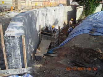
5 Cantilevered Retaining Walls Bored Pile Wall Cantilevered Retaining Walls Caisson Wall / Bored Pile Wall Eliminate/reduce temporary cut behind wall Heavy construction plant Temporary platform required on sloping ground (or provide temporary cut for sitting plant on level ground) Can be wholly in soil or socketted into bedrock. Retaining height can be up to 15m, depending on pile diameter. Caisson wall Bored-pile wall Cantilevered Retaining Walls Cantilevered Retaining Walls Bored Pile Wall Soldier Pile Wall Lighter construction plant compared with bored pile wall Retaining height up to about 6m. Skin wall to be provided. Can also be constructed as secant pile wall. Temporary steel platform for bored pile wall construction.


6 Cantilevered Retaining Walls Soldier Pile Wall Cantilevered Retaining Walls Soldier Pile Wall Soldier piles can also be installed by overburden drilling, similar to socketed H-piles Concentric overburden drill heads Soldier pile installation by Continuous Flight Auger Pile drilling with casing Down-the-hole drill head for rock socket Cantilevered Retaining Walls Cantilevered Retaining Walls Soldier Pile Wall Secant pile wall Soldier pile wall with skin wall under construction


7 Improvement to Existing Retaining Walls Soil Nailing Improvement to Existing Retaining Walls Soil Nailing Soil nails contribute to the stability of the wall by adding resisting force and moment. Though seldom, soil nails can also be used for new retaining walls. Masonry wall improved by soil nailing Improvement to Existing Retaining Walls Soil Nailing Improvement to Existing Retaining Walls Skin Wall R.C. wall improved by soil nailing The skin wall contributes to the stability of the wall by adding dead weight and increasing moment arm of resisting moment.
 - GEOGUIDE 1 (Second Edition) - Guide to Retaining Wall Design PNAP ADV-8 (PNAP 168) - Registration of Slopes and Retaining Walls PNAP ADV-23 (PNAP")
 Geoguide 6 Guide to Reinforced Earth Structure and Slope Design Geoguide 7 Guide to Soil Nail Design and Construction (for design of soil nails in retaining walls) Codes")
8 Improvement to Existing Retaining Walls Skin Wall Design and Construction Considerations Building (Construction) Regulations PNAP APP-54 (PNAP 142) - Retaining Walls - Building (Construction) Regulations Part XIII PNAP APP-63 (PNAP 166) - GEOGUIDE 1 (Second Edition) - Guide to Retaining Wall Design PNAP ADV-8 (PNAP 168) - Registration of Slopes and Retaining Walls PNAP ADV-23 (PNAP 270) - Improvement of Visual Appearance and Landscape Treatment for Man-made Slopes and Retaining Walls Geoguide 1 - Guide to Retaining Wall Design (for new walls) Geotechnical Manual for Slopes (for upgrading of existing walls) Geoguide 6 Guide to Reinforced Earth Structure and Slope Design Geoguide 7 Guide to Soil Nail Design and Construction (for design of soil nails in retaining walls) Codes of Practice for structural concrete, structural steel, foundation, etc. Building (Construction) Regulations Part XIII Retaining Walls Regulation 64 - Interpretation In this Part- "retaining wall" ( 擋土牆 ) means a structure retaining earth or fill. Regulation 65 General Requirement (1) Retaining walls shall be designed and constructed to support safely the earth or fill they retain and other loads without impairing the stability of, or causing damage to, any other building, structure, land, street or services. (2) The design and construction of minor retaining walls shall comply with subregulation (1) but shall be exempted from regulations 66 to 84. (Refer to PNAP APP-54 for definition of minor retaining walls ) Regulations 66 to 84 ( Reg 66 Filters Reg 67 Backfill Material Reg 68 Earth Pressure Reg 69 Water Pressure Reg 70 Minimum Pressure Reg 71 Retaining wall design Reg 72 Loading Condition Reg 73 Site Investigation Reg 74 Adequate Factor of Safety Reg 75 Validity of Design Earth Pressure Reg 76 Masonry and Mass Concrete Walls Reg 77 Drainage Measures to Preserve Stability Reg 78 Performance of Drainage System Reg 79 Surface Channels Reg 80 Safety Required during excavation and construction Reg 81 Weep holes Reg 82 Copings Reg 83 Bonding and Foundation Required Reg 84 Bond Courses Required

9 PNAP APP-54 (PNAP 142) - Retaining Walls Building (Construction) Regulations Part XIII) Provides clarification on Definition on Minor Retaining Walls Drainage and Filter Backfilling Material behind Retaining Wall Rock Faces Retaining Wall Design and Stability Remedial or Preventive Work to an Existing Retaining Wall Monitoring during Construction of Retaining Walls Demolition of Existing Retaining Walls PNAP 142 Retaining Walls Modes of External Instability of Mass Retaining Walls Mass Retaining Wall Actions affecting wall stability Self weight W Active earth pressure P A Passive earth pressure P p Bearing pressure N Base friction S Hydrostatic pressure at back of wall U 1 Hydrostatic pressure at wall base U 2 Surcharage Forces on retaining wall (excluding water forces) Water forces on retaining wall


10 R.C. Retaining Wall R.C. Retaining Walls Retaining Wall with Piled Foundation Virtual Back Modes of external instability same as mass retaining wall. Structural capacity of wall to be designed in accordance with Code of Practice for Structural Use of Concrete. Minipiles and socketted H-piles commonly adopted. Raking piles used to resist lateral forces. R.C. Retaining Walls Retaining Wall with Piled Foundation Cantilevered Retaining Wall External instability by Loss of Overall Stability and Overturning Failure Structural capacity of wall to be checked
11 Earth Pressures Active and Passive Earth Pressure Earth Pressures Earth Pressure Theories Active and passive pressures are dependent on soil strength parameters, c and φ. At-rest Coeff. K o Stress Strain Relationship Planar failure surface Rankine Rankine-Bell Coulomb Trial Wedge Method Ka pressure used for stability check Ko pressure used for structural design Planar-Logarithmic Spiral Caquot & Kerisel Trial Wedge Method Water Pressures Gravity and T-shaped Retaining Walls Water Pressures Cantilevered Retaining Walls Impermeable wall Bored pile/soldier pile wall Flow nets under steady state groundwater seepage Flow nets under steady state groundwater seepage
12 Compaction-induced Earth Pressures Design Standards New Retaining Walls: Geoguide 1 Guide to Retaining Wall Design Limit State Approach with partial factors of safety applied to Loads and Material Parameters Q l = Equivalent weight of roller Roll width Compaction induced pressure assumed to be clearly stated in drawings. Existing Retaining Walls: Geotechnical Manual for Slopes Factor of Safety applied to Sliding, Overturning, Bearing Capacity Overall Factor of Safety following Geotechnical Manual for Slopes to be observed in both cases. Major Inspection Items for Retaining Walls (1) Requirements on Approved Drawings and imposed by BD (2) Contractor s Submissions Method Statement, Drawings, Precautionary & Protective Measures, Materials submissions, etc. (3) Temporary Site Works Formwork, Shoring, Excavation, Temporary Cut Slope etc. (4) Permanent Site Works Founding Condition, Reinforcement Fixing, Concreting, Backfilling. For Cantilevered Walls, founding level of piles, pile verticality, pile structural steel section/pile reinforcement, grouting/concreting Sampling & Testing (1) Concrete and Steel Reinforcement CS1 : 1990 Testing Concrete CS2 : 1995 Carbon Steel Bars for the Reinforcement of Concrete (2) Formwork and Finishes to Concrete Falsework and Formwork Design (3) Founding Material Description of Soil/Rock, Plate Load Test, GCO Probe (4) Backfill Material PNAP APP-15 (PNAP 55) Site Formation Temporary & Permanent Filling Work PNAP APP-54 (PNAP 142) Retaining Walls PNAP APP-64 (PNAP 167) Methods for Testing Hong Kong Soils (GEOSPEC 3 - Model Specification for Soil Testing) (5) Drainage and Filter Material Section 8.5 of the GEOGUIDE 1 (2 nd Edition) GEO Publication No. 1/93 Review of Granular & Geotextile Filters


13 Founding Materials Code of Practice for Foundation Description of Soil / Rock Plate Loading Test Dynamic Probe Test Founding material to be protected from ingress of water after inspection If founding on piles, then design and supervision requirements of piling to be followed. Reference Code of Practice for Foundations GEOGUIDE 2 Guide to Site Investigation Code of Practice for Foundation Reinforcement Submissions Particulars of Bar Reinforcement, e.g. certificate Samples of Materials Bending Schedules Testing Tensile Test Bend Test, Rebend Test Inspection Steel Reinforcement Free of Scale Bar Size, Spacing, Lap Cover


.")

14 Reinforcement - Testing PNAP APP-45 (PNAP 122) Testing of Reinforcement for Concrete Purchaser s test referred to in CS2:1995 performed by HOKLAS laboratory Reinforcement - Testing Tensile Test Individual test result 0.93 x characteristic strength (250MPa/460MPa) Mean of test results Characteristic strength + 10MPa Not necessary to assess mean value if all individual result characteristic strength Bend Test Withstand bend through 180 with no sign of cracks on visual inspection Rebend Test Withstand bend through 45 and rebend without breaking Class 1 Reinforcement from QA manufacturers, handled by a QA Stockist and retaining manufacturer s lot traceability Class 2 Reinforcement from QA manufacturers, handled by a QA Stockist but without manufacturer s lot traceability Class 3 Reinforcement other than Class 1 and Class 2 Reinforcement - Inspection Loose rust, excessive flaky rust or mill scale removed by wire-brushing. Sufficient number of spacers, chairs (spacing 1.5m in general). Spacers to be constructed of concrete or of proprietary plastic or concrete type. Strength should not be less than surrounding concrete. Sufficient number of intersecting and lapping bars tied by tying wire or clips Access over reinforcement to be well supported to avoid displacement of reinforcment Laps in reinforcement to be provided at specified positions with design lap length. Formwork & Finishes to Concrete Submissions Falsework and Formwork Design Time for removal of Falsework & Formwork Cover Spacers, Release Agents, Formwork Tie, Surface Retarders Class of Formed, Unformed, & Treated Finishes Inspection Falsework Sealing of joints Cover to reinforcement bars


15 Formwork & Finishes to Concrete Formwork tied to existing wall Submissions Particulars of Concrete Mix Particulars of Construction Joints Testing Testing for Workability - slump Testing for Compressive Strength - cubes Concreting Inspection Preparation of joints Clearing of debris Compaction Checking of thickness of wall Concreting Slump Test Concreting Slump Test Test of workability Test procedure and details: CS1 Section 2 Sampling from each concrete truck Slump cone 300mm high Measured to nearest 5mm Note: Concrete with high workability, i.e. slump in excess of 150mm, may sometime exhibit a slump pattern similar to that of a collapse slump. In such case, the slump shall still be

, that test result shall be disregarded and investigation shall be made to establish whether the concerned concrete is acceptable or note.")

16 Concreting Concrete Cube for Compression Test Concreting Concrete Cube for Compression Test Test of compressive strength Test procedure and details: CS1 Section 12 Sampling and testing: B(C)R Reg 58 At least one sample from each grade of concrete produced on any one day Two 150mm cubes from each sample of concrete Serial number to be given to each concrete cube Cubes to be adequately cured Test for 28-day compressive strength at HOKLAS laboratory Average of compressive strength of a pair of cubes taken as test result Concreting Concrete Cube for Compression Test Acceptance Criteria: B(C)R Reg 59 If the difference in compressive strength of a pair of cubes exceeds 20% of the test result (i.e. average of the pair), that test result shall be disregarded and investigation shall be made to establish whether the concerned concrete is acceptable or note. Backfilling behind Retaining Walls According to APP-54 (PNAP 142) 1. Backfill material behind retaining walls should have properties that meet design requirements. It should also meet the requirements in Table 1 at Appendix A attached. 2. Material selected for use as backfill generally must not contain : (a) peat, vegetation, timber, organic or other degradable materials; (b) dangerous or toxic material; (c) material susceptible to combustion; (d) metal, rubber, plastic or synthetic material; (e) material susceptible to significant volume change e.g. marine mud, swelling clays and collapsible soils; or (f) soluble material. 3. In addition, the backfill should not be chemically aggressive : e.g. the presence of excessive sulphate in soils can cause accelerated deterioration of concrete and steel.

17 Backfilling behind Retaining Walls PNAP APP-54 (PNAP 142) Appendix A Table 1 Backfilling behind Retaining Walls According to PNAP APP-15 (PNAP 55) The in situ field dry densities of compacted materials forming the peripheral portion of an earth fill slope shall be not less than 95% of the maximum dry density Relative Compaction = In situ dry density Max. dry density > 95% Backfilling behind Retaining Walls PNAP APP-15 (PNAP 55) Testing Frequency Backfilling behind Retaining Walls In situ Field Tests : Sand Replacement Method => determine in situ bulk density (Geospec 3 Test Method 11.1 or 11.2) Nuclear Densometer Method => determine in situ bulk density (Geospec 3 Test Method 11.3) Speedy Test => obtain in situ moisture content (advance information) Laboratory Tests : Oven-drying => determine moisture content (Geospec 3 Test Method 5.1 to 5.3) Geospec 3 Test Method 10.1 to 10.8 => determine max. dry density (Proctor Test) & optimum moisture content


 GEO Publication No.")
18 Backfilling behind Retaining Walls Sand Replacement Test Backfilling behind Retaining Walls Relative Compaction Test Backfilling behind Retaining Walls PNAP 167 Methods for Testing Hong Kong Soils (GEOSPEC 3 - Model Specification for Soil Testing) Where soil tests are to be carried out, only laboratories accredited under the Hong Kong Laboratory Accreditation Scheme (HOKLAS) for the relevant tests shall be employed. The BA will only accept results issued on HOKLAS-endorsed test certificates or reports. Two Types : (i) Granular Filters (ii) Geotextile Filters Drainage and Filter Material Section 8.5 of the GEOGUIDE 1 (2 nd Edition) GEO Publication No. 1/93 Review of Granular & Geotextile Filters

 Stability pores small enough to prevent excessive")


19 Drainage and Filter Material GEO Publication No. 1/93 Review of Granular & Geotextile Filters Drainage and Filter Material GEO Publication No. 1/93 Review of Granular & Geotextile Filters (Extracted from GEO Publication No. 1/93) Stability pores small enough to prevent excessive migration of base soil Permeability more permeable than base soil Segregation Not segregated/contaminated during and after installation Min. thickness 300mm Drainage and Filter Material GEO Publication No. 1/93 Review of Granular & Geotextile Filters Construction of Cantilevered Pile Wall Predrilling For piles designed to be socketted into rock (Grade III Rock with TCR>85%, UCS>25MPa +&PL 50 >1MPa) Pre-drilling Rig Measuring Depth of Drillhole Drillhole Core Box


20 Construction of Cantilevered Pile Wall Construction of Cantilevered Pile Wall Koden Test Checking of bored pile section and verticality Confirmation of Founding Level Inspection of rock sample at founding level Measuring the depth for the founding level Construction of Cantilevered Pile Wall Construction of Cantilevered Pile Wall Koden Test Checking of bored pile section and verticality Checking of cleanliness of water before concreting Air-lifting Inspection of Water Sample


21 Checking of Steel Cage Construction of Cantilevered Pile Wall Construction of Cantilevered Pile Wall Concreting of bored pile by tremie method Use of Pump Truck Concreting by Hopper Construction of Cantilevered Pile Wall Checking of pile integrity Full Core Sonic Test Construction of Cantilevered Pile Wall Sonic Test Checking of pile integrity

")
22 Construction of Cantilevered Pile Wall Verticality Check for Soldier Pile Wall Test of grout (Flow cone test, bleeding test, cube strength) The End
Geoguide 6 The New Guide to Reinforced Fill Structure and Slope Design in Hong Kong
 Geoguide 6 The New Guide to Reinforced Fill Structure and Slope Design in Hong Kong Geotechnical Engineering Office Civil Engineering Department The Government of the Hong Kong Special Administrative Region
SPECIFICATION FOR REINFORCED SOIL WALL
 SPECIFICATION FOR REINFORCED SOIL WALL 1.0 EXTENT OF WORK The work shall consist of Reinforced Soil walls built in accordance with this specification and in conformity with the lines, levels and details
SPECIFICATIONS FOR PRECAST MODULAR BLOCK RETAINING WALL SYSTEM (revised 5/8/7)
") Page 1 of 7 STONE STRONG SYSTEMS SPECIFICATIONS FOR PRECAST MODULAR BLOCK RETAINING WALL SYSTEM (revised 5/8/7) PART 1: GENERAL 1.01 Description A. Work includes furnishing and installing precast modular
Page 1 of 7 STONE STRONG SYSTEMS SPECIFICATIONS FOR PRECAST MODULAR BLOCK RETAINING WALL SYSTEM (revised 5/8/7) PART 1: GENERAL 1.01 Description A. Work includes furnishing and installing precast modular
RETAINING WALLS CHAPTER 13. Omitted parts: Section
 RETAINING WALLS CHAPTER 13 Omitted parts: Section 13.9 13.15-13.17 INTRODUCTION Retaining walls are structures that restrain soil or other materials at locations having an abrupt change in elevation. In
Chapter 18 EARTH RETAINING STRUCTURES
 Chapter 18 EARTH RETAINING STRUCTURES Final SCDOT GEOTECHNICAL DESIGN MANUAL June 2010 SCDOT Geotechnical Design Manual Earth Retaining Structures Table of Contents Section Page 18.1 Introduction...18-1
ENGINEERING DIRECTIVE
 Number: E-95-001 Date: 2/2/95 ENGINEERING DIRECTIVE Ross B. Dindio (Signature on Original) CHIEF ENGINEER The purpose of this engineering directive is to formally notify ALL Department engineering personnel
Topic: Site Formation
 Topic: Site Formation Presentation prepared by Raymond Wong February 2006 Purpose of site formation is to prepare a piece of land in order to: Accommodate building/s or other facilities which will be placed
DESIGN OF RETAINING WALLS
 DESIGN OF RETAINING WALLS Dr. Izni Syahrizal bin Ibrahim Faculty of Civil Engineering Universiti Teknologi Malaysia Email: iznisyahrizal@utm.my Introduction Retaining wall is used to retain earth or other
Soil Mechanics Lateral Earth Pressures page Lateral Earth Pressures in case of inclined ground surface or friction at wall-ground interface
 Soil Mechanics Lateral Earth Pressures page 9 7.6 Lateral Earth Pressures in case of inclined ground surface or friction at wall-ground interface By now, we have considered the wall as perfectly smooth
Lecture Retaining Wall Week 12
 Lecture Retaining Wall Week 12 Retaining walls which provide lateral support to earth fill embankment or any other form of material which they retain them in vertical position. These walls are also usually
5-20 FOUNDATION REPORT/GEOTECHNICAL DESIGN
 5-20 FOUNDATION REPORT/GEOTECHNICAL DESIGN REPORT CHECKLIST FOR EARTH RETAINING SYSTEMS Introduction This checklist was developed to assist the geotechnical project professionals in preparing the Foundation
DESIGNING AND CONSTRUCTION OF T-WALL RETAINING WALL SYSTEM
 Istanbul Bridge Conference August 11-13, 2014 Istanbul, Turkey DESIGNING AND CONSTRUCTION OF T-WALL RETAINING WALL SYSTEM T. C. NEEL and K.BOZKURT ABSTRACT This work shall consist of the design, manufacture
SPECIFICATION FOR PIPE CULVERT CONSTRUCTION
 SPECIFICATION FOR PIPE CULVERT CONSTRUCTION 1. SCOPE Pipe culverts shall be constructed in accordance with this specification and in conformity with the lines, levels and cross-sections shown on the drawings.
Retaining Wall Design
 SIL 211 MEKANIKA TANAH Retaining Wall Design DR. IR. ERIZAL, MAGR DEPARTEMEN TEKNIK SIPIL DAN LINGKUNGAN FAKULTAS TEKNOLOGI PERTANIAN IPB 1 Conventional Retaining Walls Gravity Retaining Structures Stability
7. Draw an equipment set up for the production of a beam by post tensioning. 10. What are the common concrete structures which are produced by
 Construction Technology B (CON4313) Self Assessment Questions: Chapter 1 Prestressed Concrete 1. How does the prestressing of steel tendons in prestressed concrete offer a higher loading capacity than
VERTI-BLOCK - DESIGN MANUAL
 Company Information General Information Verti-Block is the latest innovative forming system from Verti-Crete, LLC. Recognized worldwide for outstanding aesthetics and performance, Verti-Crete s proprietary
Classification of slope
 Slope Protection Classification of slope Natural slope in various conditions, including rock slope Man-made slope - including cut-back slope or slope formed by filled material with adequate compaction,
THE OF KONG LIBRARIES. Hong Collection gift from ; Hong Kong. Civil Engineering Dept.
 THE OF KONG LIBRARIES Hong Collection gift from ; Hong Kong. Civil Engineering Dept. GEOGUIDE 1 GUIDE TO RETAINING WALL DESIGN GEOTECHNICAL ENGINEERING OFFICE Civil Engineering Department Hong Kong..,
RETAINING WALL LEVEL BACKFILL
 City of Poway Development Services Department Building Division (858) 668-4645 (858) 668-4646 (Inspection Line) building@poway.org RETAINING WALL LEVEL BACKFILL Construction of retaining walls, except
Geotechnical Engineering Software GEO5
 Geotechnical Engineering Software GEO5 GEO5 software suite is designed to solve various geotechnical problems. The easy -to -use suite consists of individual programs with an unified and user-friendly
Geotechnical standards in Hong Kong
 Geotechnical standards in Hong Kong ACECC Workshop on Harmonization of Design Codes in Asian Region November 4, 2006, Taipei, Taiwan L. M. Mak President, Hong Kong Geotechnical Society (This paper has
1 Exam Prep Placing Reinforcing Bars Tabs and Highlights
 1 Exam Prep Placing Reinforcing Bars Tabs and s These 1 Exam Prep Tabs are based on the CRSI Placing Reinforcing Bars Recommended Practices, 9 th Edition. Each 1 Exam Prep tabs sheet has five rows of tabs.
Description. This work shall consist of furnishing materials and placement of modular block wall constructed in accordance with
 MODULAR CONCRETE BLOCK RETAINING WALL WITH GROUND REINFORCING The Standard Specifications are revised as follows: 732-R-310r 1of 11 Rev. 12-03-03 SECTION 105, AFTER LINE 48, INSERT AS FOLLOWS: When constructing
Method of Measurement for Road Works Series MM Structural Concrete
 Method of Measurement for Road Works Series MM 1700 - CC-RMP-01700 December 2013 CC Construction & Commissioning Standards TRANSPORT INFRASTRUCTURE IRELAND (TII) PUBLICATIONS About TII Transport Infrastructure
MOA Project # Golden View Drive Intersection & Safety Upgrades
 Appropriate transitions can include extending the insulation beyond the roadway improvements, reducing the insulation thickness, or angling the insulation downward. Use of a frost tolerant section, an
Case Studies on Soil Nailed Retaining Systems for Deep Excavations
 Indian Geotechnical Conference 2010, GEOtrendz December 16 18, 2010 IGS Mumbai Chapter & IIT Bombay Case Studies on Soil Nailed Retaining Systems for Deep Excavations Murthy, B.R. Srinivasa Professor e-mail:
ODOT Design & Construction Requirements for MSE Walls
 ODOT Design & Construction Requirements for MSE Walls Peter Narsavage, P.E. Foundation Engineering Coordinator Ohio Department of Transportation Office of Structural Engineering 2006 Ohio Transportation
Design Manual: Gravity Wall. Section 1
 Design Manual: Gravity Wall Section 1 A Design Manual: Gravity Wall General Information Company Information Verti-Block is the latest innovative forming system from Verti-Crete, LLC. Recognized worldwide
SECTION SPECIFICATION FOR STONEBRIDGE RETAINING WALL SYSTEM
 SECTION 32 32 23 SPECIFICATION FOR STONEBRIDGE RETAINING WALL SYSTEM PART 1: GENERAL 1.01 Scope Work includes furnishing all materials, labor, equipment, and supervision to install a Stonebridge segmental
REPORT STATUS: DATE: Report n :
 REPORT: Expanded clay LWA in CEA Lightweight fill and thermal insulation products for civil engineering applications. Installation and structural quality control on site. STATUS: Technical report DATE:
ICC-ES Evaluation Report Issued July 1, 2011 This report is subject to renewal in one year.
 ICC-ES Evaluation Report ESR-1959 Issued July 1, 2011 This report is subject to renewal in one year. www.icc-es.org (800) 423-6587 (562) 699-0543 A Subsidiary of the International Code Council DIVISION:
PRODUCT DATA SHEET SikaProof Bentonite
 PRODUCT DATA SHEET NATURAL SODIUM BENTONITE BELOW GROUND WATERPROOFING SYSTEM (ONLY TO BE APPLIED BY A SIKA APPROVED CONTRACTOR) PRODUCT DESCRIPTION SikaProof Bentonite is a needle punched thermally locked
Method of Measurement for Road Works Series MM Earthworks
 Method of Measurement for Road Works Series MM 600 - CC-RMP-00600 March 2013 CC Construction & Commissioning Standards TRANSPORT INFRASTRUCTURE IRELAND (TII) PUBLICATIONS About TII Transport Infrastructure
Redi Rock Specification and Installation Manual
 Redi Rock Specification and Installation Manual 1.0 General Scope This Specification covers the Design, Materials and Installation of Redi Rock modular block Retaining and Freestanding Wall systems as
Chapter 13: Retaining Walls
 Chapter 13: Retaining Walls Introduction In general, retaining walls can be divided into two major categories: (a) conventional retaining walls and (b) mechanically stabilized earth walls Conventional
Design Illustrations on the Use of Soil Nails to Upgrade Loose Fill Slopes
 Design Illustrations on the Use of Soil Nails to Upgrade Loose Fill Slopes Geotechnical Engineering Office and The Hong Kong Institution of Engineers (Geotechnical Division) November 2013 2 Disclaimer
Design of Semi gravity Retaining Walls
 Design of Semi gravity Retaining Walls Example 13.1 A semi gravity retaining wall consisting of plain concrete (weight = 145 lb/ft³) is shown in Figure 13.9. The bank of supported earth is assumed to weigh
Advance Design of RC Structure Retaining Wall
 1 Retaining Wall Retaining Walls What are retaining walls Retaining walls are soil-structure systems intended to support earth backfills. Type of retaining walls Gravity retaining wall gravity walls rely
Oweninny Wind Farm. Oweninny Environmental Impact Statement Appendix 5. Turbine Foundation Construction Method Statement
 Oweninny Wind Farm Oweninny Environmental Impact Statement Appendix 5 Turbine Foundation Construction Method Statement Copyright ESB International Limited, all rights reserved. Farm Contents 1 Introduction
DESIGN AND DETAILING OF RETAINING WALLS
 DESIGN AND DETAILING OF RETAINING WALLS (For class held from nd April 07) Dr. M. C. Nataraja, Professor, Civil Engineering Department, Sri Jayachamarajendra Collge of Engineering, Mysore-5a70 006 Phone:
DESIGN CONSIDERATIONS FOR NSWS NATURAL STONE RETAINING AND FREE-STANDING WALL SYSTEMS
 DESIGN CONSIDERATIONS FOR NSWS NATURAL STONE RETAINING AND FREE-STANDING WALL SYSTEMS Natural Stone Wall Solutions, Inc (NSWS ) 2352 Main Street, Suite 103 Concord, MA 01742 (978) 461-1777 Concept and
MSE WALLS CASE STUDIES. by John G. Delphia, P.E. TxDOT Bridge Division Geotechnical Branch
 MSE WALLS CASE STUDIES by John G. Delphia, P.E. TxDOT Bridge Division Geotechnical Branch COMMON RETAINING WALL TYPES CONCRETE BLOCK MSE TEMPORARY EARTH SPREAD FOOTING Gabions Drilled Shaft Soil Nail Tiedback
CF50/100 KW TURBINE ACCESS ROAD, CRANE PLATFORM, CONCRETE, AND LIFTING SPECIFICATIONS C&F GREEN ENERGY REVISION PREPARED BY APPROVED BY DATE
 CF50/100 KW TURBINE ACCESS ROAD, CRANE PLATFORM, CONCRETE, AND LIFTING SPECIFICATIONS C&F GREEN ENERGY REVISION PREPARED BY APPROVED BY DATE 001 First Draft W Hession 12.02.2014 Introduction This document
2.1 Backfill - General
 2.1 Backfill - General Excavations are made for the purpose of constructing bridge substructure elements, and consequently requiring competent backfill material. The backfill material must be adequately
METHOD STATEMENT for INSTALLATION OF MICROPILE
 METHOD STATEMENT for INSTALLATION OF MICROPILE A. MATERIAL TO BE USED 1. Grout Grout shall be mixed from Ordinary Portland Cement and clean water free from harmful substances. Usage of other cement which
PIANC UK Seminar Design Developments and Specification for Steel. Duncan Nicholson Arup Fellow 9/3/17 ICE London
 PIANC UK Seminar Design Developments and Specification for Steel Duncan Nicholson Arup Fellow 9/3/17 ICE London Contents 1. Design Issues 2. SPERWall Edition 3 (2016) 1. Steel Sheet Piles (Section 14)
STANDARD SPECIFICATION FOR CRIBLOCK CONCRETE CRIBWALL
 STANDARD SPECIFICATION FOR CRIBLOCK CONCRETE CRIBWALL 1. SCOPE 2. DESIGN 3. MATERIALS 4. CONSTRUCTION 5. METHOD OF MEASUREMENT AND PAYMENT SCOPE This Specification sets out requirements for the design,
SPECIFICATION FOR ENGINEERED FILLS
 SPECIFICATION FOR ENGINEERED FILLS This specification is intended to be used for the engineered fill. The specification is suitable for most purposes but there may be special conditions existing at some
LANDSCAPE RETAINING WALLS
 SUDAS Standard Specifications Division 9 - Site Work and Landscaping Section 9070 - Landscape Retaining Walls LANDSCAPE RETAINING WALLS PART - GENERAL.0 SECTION INCLUDES A. Modular Block Retaining Walls
A.2.a Random Riprap... Table
 3601 RIPRAP MATERIAL 3601.1 SCOPE Provide stone and filter layer material for use in random or hand-placed riprap, gabion, and revet mattress construction. 3601.2 REQUIREMENTS A Stones A.1 Quality Provide
Design and Installation Guidelines for Retaining Walls. 1 P age. Geo Products, LLC 8615 Golden Spike Lane Houston, TX Phone:
 Design and Installation Guidelines for Retaining Walls 1 P age Geo Products, LLC 8615 Golden Spike Lane Houston, TX 77086 Phone: 281.820.5493 2011 Geo Products, Fax: 281.820.5499 LLC www.geoproducts.org
Bureau of Materials Materials Approval Procedures
 Bureau of Materials Materials Approval Procedures MAP Number: 116-15 Effective Date: April 1, 2015 Approved By: Eileen Sheehy PROCEDURE FOR APPROVAL OF MECHANICALLY STABILIZED EARTH (MSE) RETAINING WALL
T-WALL & STONE STRONG
 shawprecastsolutions.com & STONE STRONG Retaining Walls PRODUCT GUIDE & TECHNICAL REFERENCE MANUAL Providing the right solutions. The Retaining Wall System is a gravity structure constructed of individual
STORMCAPTURE. Installation Manual
 STORMCAPTURE Installation Manual Introduction Site Preparation Delivery & Installation LinkSlabs Backfill Introduction StormCapture (shown in Figure 1) is a total stormwater management system. The highly-configurable
EN REINFORCED MASONRY DESIGN EXAMPLE 1 (NOTE: THIS USES THE UK NATIONAL ANNEX NDP VALUES)
") 42.50 10.00 3.00 20.00 EN 1996-1-1 REINFORCED MASONRY DESIGN EXAMPLE 1 (NOTE: THIS USES THE UK NATIONAL ANNEX NDP VALUES) Reinforced Masonry - Reinforced Brickwork Stem Cantilever Pocket-Type Retaining
42.50 10.00 3.00 20.00 EN 1996-1-1 REINFORCED MASONRY DESIGN EXAMPLE 1 (NOTE: THIS USES THE UK NATIONAL ANNEX NDP VALUES) Reinforced Masonry - Reinforced Brickwork Stem Cantilever Pocket-Type Retaining
CHANGES IN 2006 SPECIFICATIONS SECTION 804 DRIVEN PILES SECTION 814 DRILLED SHAFTS
 CHANGES IN 2006 SPECIFICATIONS SECTION 804 DRIVEN PILES SECTION 814 DRILLED SHAFTS 2006 LADOTD ENGINEERING CONFERENCE Kim Martindale Garlington, P.E. Pavement & Geotechnical Services February 13, 2007
INNOVATIVE SLOPE STABILISATION BY USING ISCHEBECK TITAN SOIL NAILS
 Dipl.-Wirt.Ing. Oliver Freudenreich Friedr. Ischebeck GmbH phone: ++49 2333 8305-0 Loher Str. 31 79 fax: ++49 2333 8305-55 e-mail: freudenreich@ischebeck.de D-58256 Ennepetal www.ischebeck.com INNOVATIVE
INDEX FOR SPECIFICATIONS FOR JACKING CULVERTS THROUGH EMBANKMENTS SCOPE... 2
 INDEX FOR SPECIFICATIONS FOR JACKING CULVERTS THROUGH EMBANKMENTS 410. 1 SCOPE... 2 410. 2 DEFINITIONS 2.1 Tunneling and Jacking... 2 2.2 Tunneling... 2 2.3 Jacking... 2 410. 3 MATERIALS 3.1 General...
SECTION EXCAVATION AND EMBANKMENT. B. Subbase Grading A samples for gradation analysis.
 PART 1 GENERAL 1.1 DESCRIPTION A. The WORK under this Section includes providing all labor, materials, tools and equipment necessary for excavation and embankment construction to the lines, grades and
Anchorplex retaining wall construction guide. Building. Anchorplex. Retaining Wall Systems
 Anchorplex retaining wall construction guide Building Anchorplex Retaining Wall Systems Table of Contents and ow to Use This Guide table of contents ow to Use This Guide. 2 About the Anchorplex System.
Soils and Foundations for Architects and Engineers
 Soils and Foundations for Architects and Engineers Soils and Foundations for Architects and Engineers Chester I. Duncan, Jr., FASCE Professor of Architecture The University of Texas at Arlington I RUf?TURA~
Moll s Gap- Soil Nail Remediation of a Collapsed Retaining Wall Co. Kerry, Ireland
 Moll s Gap- Soil Nail Remediation of a Collapsed Retaining Wall Co. Kerry, Ireland Chris Bailey BSc (Hons) MSc CGeol FGS RoGEP Senior Engineering Geologist ATKINS 29 September 2017, TII Annual Conference,
Statement of Special Inspections Michigan Building Code 2012 (MBC 2012)
") Gaines Charter Township 8555 Kalamazoo Ave SE Caledonia MI 49316 PH: 616 698-6640 Fax: 616 698-2490 www.gainestownship.org Building Department Statement of Special Inspections Michigan Building Code 2012
Gaines Charter Township 8555 Kalamazoo Ave SE Caledonia MI 49316 PH: 616 698-6640 Fax: 616 698-2490 www.gainestownship.org Building Department Statement of Special Inspections Michigan Building Code 2012
SEMINAR. Introduction to Continuous Flight Auger (CFA) piling Thursday 21/8/2013. Facilitator: Martin Larisch
 piling Thursday 21/8/2013. Facilitator: Martin Larisch") SEMINAR Introduction to Continuous Flight Auger (CFA) piling Thursday 21/8/2013 Facilitator: Martin Larisch 1 Brief History of Piling Contractors, its capabilities and market Introduction to CFA piling
SEMINAR Introduction to Continuous Flight Auger (CFA) piling Thursday 21/8/2013 Facilitator: Martin Larisch 1 Brief History of Piling Contractors, its capabilities and market Introduction to CFA piling
Possible solution to past CM exam question. Question 2 July New city centre office block. by Rajavel Inbarajan
 Possible solution to past CM exam question Question 2 July 2015 New city centre office block by Rajavel Inbarajan The information provided should be seen as an interpretation of the brief and a possible
Construction Specification for Utility Adjustments
 Engineering & Construction Services Division Standard Specifications for Road Works TS 4.50 September 2017 for Utility Adjustments Table of Contents TS 4.50.01 SCOPE... 2 TS 4.50.02 REFERENCES... 2 TS
Water Well Decommissioning Guidelines
 Water Well Decommissioning Guidelines Approval Date: June 1, 2007 Effective Date: September 10, 2007 Approved By: Gerard MacLellan Version Control: This is a new guideline I. Introduction The Water Well
NPTEL Course GROUND IMPROVEMENT USING MICROPILES
 Lecture 22 NPTEL Course GROUND IMPROVEMENT USING MICROPILES Prof. G L Sivakumar Babu Department of Civil Engineering Indian Institute of Science Bangalore 560012 Email: gls@civil.iisc.ernet.in Contents
Earthquake Design of Flexible Soil Retaining Structures
 Earthquake Design of Flexible Soil Retaining Structures J.H. Wood John Wood Consulting, Lower Hutt 207 NZSEE Conference ABSTRACT: Many soil retaining wall structures are restrained from outward sliding
Structural Tests and Special Inspections Form. Inspection of Fabricators (1704.2)
") Inspection of Fabricators (1704.2) Furnish inspection reports (1704.2.1) - Fabricators that have not been approved Provide a Certificate of Compliance (1704.2.2) - Approved Fabricators Steel Construction
Inspection of Fabricators (1704.2) Furnish inspection reports (1704.2.1) - Fabricators that have not been approved Provide a Certificate of Compliance (1704.2.2) - Approved Fabricators Steel Construction
Drill Shaft Contractor and Equipment Arrive On-Site CBT Script
 Drill Shaft Contractor and Equipment Arrive On-Site CBT Script Welcome to the Drilled Shaft Inspector Course. This is Lesson 5, Contractor and equipment Arrive On-Site. To begin, select the start button
INSPECTION GUIDE FOR SEGMENTAL RETAINING WALLS TEK 18-11B
 An information series from the national authority on concrete masonry technology INSPECTION GUIDE FOR SEGMENTAL RETAINING WALLS TEK 18-11B Quality Assurance and Testing (2012) INTRODUCTION Segmental retaining
MECHANICALLY STABILIZED EARTH (MSE) WALL SYSTEMS
 WALL SYSTEMS") DRAINAGE SOLUTIONS SINCE 1908 MECHANICALLY STABILIZED EARTH (MSE) WALL SYSTEMS PERMANENT AND TEMPORARY ENGINEERED WALL SOLUTIONS ECONOMICAL DURABLE VERSATILE ARMTEC.COM MSE RETAINING WALLS Armtec Mechanically
DRAINAGE SOLUTIONS SINCE 1908 MECHANICALLY STABILIZED EARTH (MSE) WALL SYSTEMS PERMANENT AND TEMPORARY ENGINEERED WALL SOLUTIONS ECONOMICAL DURABLE VERSATILE ARMTEC.COM MSE RETAINING WALLS Armtec Mechanically
Anchor bolts ASTM F1554, Gr. 36 Wide flange beams ASTM A992, Fy = 50 ksi Misc. structural steel ASTM A36, Fy = 36 ksi
 STRUCTURAL NOTES MATERIAL STRENGTHS Structural Steel Reinforcing Steel Concrete Masonry Structural Lumber Anchor bolts ASTM F1554, Gr. 36 Wide flange beams ASTM A992, Fy = 50 ksi Misc. structural steel
CONCRETE SEGMENTAL RETAINING WALL SYSTEM
 CONCRETE SEGMENTAL RETAINING WALL SYSTEM PART 1: GENERAL SPECIFICATIONS 1.01 Work Included A. Work shall consist of furnishing and constructing a Rockwood Classic 8, Classic 6 and Legend unit segmental
QCS 2014 Section 04: Foundations and Retaining Structures Page 1 Part 01: General Requirements for Piling Work
 2014 Section 04: Foundations and Retaining Structures Page 1 Part 01: General Requirements for Piling Work 1 GENERAL REQUIREMENTS FOR PILING WORK... 2 1.1 GENERAL... 2 1.1.1 Scope 2 1.1.2 References 2
Providing proper drainage system
 Environment Friendly and Cost Effective Alternative to Conventional Graded Filters Providing proper drainage system for structures such as earth retaining structures, pavements, water front structures,
TensarTech TW1 Wall System Earth Retaining Structures
 Tensar model specification MS/TW1S_1 Issue date 28 February 2014 TensarTech TW1 Wall System Earth Retaining Structures This document is intended to form a basis for Tender documents where the following
SECTION CAST-IN-PLACE CONCRETE
 SECTION 03300 CAST-IN-PLACE CONCRETE PART 1 GENERAL 1.01 SECTION INCLUDES A. The Contractor shall furnish all work and materials, including cement, sand and coarse aggregate, water, admixtures, curing
CONTINUOUS FLIGHT AUGER (CFA) PILES QC/QA PROCEDURES. Preferred QC/QA Procedures
 PILES QC/QA PROCEDURES. Preferred QC/QA Procedures") Preferred QC/QA Procedures The Federal Highway Administration (FHWA) has provided QC/QA guidance for this technology as noted below. The reference document also contains information about construction
Preferred QC/QA Procedures The Federal Highway Administration (FHWA) has provided QC/QA guidance for this technology as noted below. The reference document also contains information about construction
Performance of Mechanically Stabilized Earth walls over compressible soils
 Performance of Mechanically Stabilized Earth walls over compressible soils R.A. Bloomfield, A.F. Soliman and A. Abraham The Reinforced Earth Company, Vienna, Virginia, USA ABSTRACT: Two projects have recently
SPECIFICATIONS FOR BRIDGE CONSTRUCTION SECTION 2 BACKFILL. 2.1 General...2-1
 SPECIFICATIONS FOR BRIDGE CONSTRUCTION SECTION 2 BACKFILL TABLE OF CONTENTS 2.1 General...2-1 2.2 Materials...2-1 2.2.1 Compacted Non-granular Material...2-1 2.2.2 Gravel Material and Crushed Aggregate
CIVIL BREADTH Exam Specifications
 NCEES Principles and Practice of Engineering Examination CIVIL BREADTH and STRUCTURAL DEPTH Exam Specifications Effective Beginning with the April 2015 Examinations The civil exam is a breadth and depth
SPECIFICATIONS FOR BRIDGE CONSTRUCTION SECTION 5 REINFORCING STEEL. 5.1 General Certification Fabrication...
 SPECIFICATIONS FOR BRIDGE CONSTRUCTION SECTION 5 REINFORCING STEEL TABLE OF CONTENTS 5.1 General...5-1 5.2 Certification...5-1 5.3 Fabrication...5-1 5.4 Handling and Storage...5-1 5.5 Field Repair of Epoxy
UNDERPINNING A CRANE FOUNDATION
 UNDERPINNING A CRANE FOUNDATION Donald R. McMahon, P.E., McMahon & Mann Consulting Engineers, P.C., Buffalo, New York, USA Andrew J. Nichols, P.E., McMahon & Mann Consulting Engineers, P.C., Buffalo, New
SEGMENTAL BLOCK RETAINING WALLS. Comply with Division 1 - General Provisions and Covenants, as well as the following:
 SEGMENTAL BLOCK RETAINING WALLS PART 1 - GENERAL 1.01 SECTION INCLUDES Segmental Block Retaining Walls 1.02 DESCRIPTION OF WORK Constructing segmental block retaining walls. 1.03 SUBMITTALS Comply with
AUGUST 2017 HASTINGS. retaining walls installation guide
 AUGUST 2017 HASTINGS retaining walls installation guide RETAINING WALL INSTALLATION GUIDE RETAINING WALL information Austral Masonry retaining wall blocks are an ideal choice for retaining walls in gardens,
CONTRACTOR AND EQUIPMENT ARRIVE ON-SITE
 Lesson 5 Inspector CONTRACTOR AND EQUIPMENT ARRIVE ON-SITE Drilled Shaft Installation Plan 5-1 Version 1-1/15 5-1 Learning Outcomes Identify and understand the Role and Duties of the Inspector Verify and
Retaining Walls. Made Easy
 Retaining Walls Made Easy Retaining Walls Made Easy! Contents Page 1 Contents Page 2 Foreword Page 3 Demolition Page 3 Removal Vegetation Page 3 Excavation Page 4 Reinforcement Steel Page 6 Concreting
TRENCHLESS CONSTRUCTION (BORING, JACKING, AND TUNNELING)
") PART 1 - GENERAL TRENCHLESS CONSTRUCTION (BORING, JACKING, AND TUNNELING) 1.01 SECTION INCLUDES A. Trenchless Installation of Carrier Pipe with Casing Pipe B. Trenchless Installation of Carrier Pipe without
PART 1 - GENERAL TRENCHLESS CONSTRUCTION (BORING, JACKING, AND TUNNELING) 1.01 SECTION INCLUDES A. Trenchless Installation of Carrier Pipe with Casing Pipe B. Trenchless Installation of Carrier Pipe without
Temporary Shoring. Specifications, Applications, & Best Practices. Stephen M. (Matt) Revell, P.E. Assistant Geotechnical Engineer
 Revell, P.E. Assistant Geotechnical Engineer") Temporary Shoring Specifications, Applications, & Best Practices Stephen M. (Matt) Revell, P.E. Assistant Geotechnical Engineer Temporary Shoring Specifications, Applications, & Best Practices Temporary
Temporary Shoring Specifications, Applications, & Best Practices Stephen M. (Matt) Revell, P.E. Assistant Geotechnical Engineer Temporary Shoring Specifications, Applications, & Best Practices Temporary
BISON PRECAST FLOORING SPECIFICATION
 BISON PRECAST FLOORING SPECIFICATION 1.0 SCOPE OF THE SPECIFICATION 1.01 Relates to: This specification covers the design, manufacture and associated site work of the following types of floors:- Hollowcore
HIGH TENSION LOAD TRANSFER USING BORED PILES FOR SOUL APARTMENTS, Surfers Paradise
 HIGH TENSION LOAD TRANSFER USING BORED PILES FOR SOUL APARTMENTS, Surfers Paradise Martin Larisch Piling Contractors Pty Ltd ABSTRACT This paper describes two different methodologies of transferring high
SECTION XXXX POLYMER CONCRETE PUMP STATIONS
 SECTION XXXX POLYMER CONCRETE PUMP STATIONS PART 1 GENERAL 1.1 SUMMARY A. This specification shall govern for the furnishing of all work necessary for installation of polymer concrete pump stations to
Geotech Services, X-18, MIDC, Hingna, Nagpur, Maharashtra. Discipline Mechanical Testing Issue Date
 Last Amended on 11.01.2014 Page 1 of 14 I. BUILDING MATERIALS 1. Soil / Rock Plate Load Test IS 1888 1982 (Reaffirmed-2007) Cyclic Plate Load Test IS 5249 1992 Clause 6 (Reaffirmed-2010) Load Test On In-Situ
TUNNEL LINER PLATE INTRODUCTION GENERAL APPLICATIONS CHAPTER 11
 CHAPTER 11 INTRODUCTION The open-trench method of placing underground conduits is commonly used on new construction of culverts, sewers and underpasses. Interference with traffic, as well as inconvenience
The Technical and Contractual Matters of Bored Piling Works. By Wallace Yeung Vibro (H.K.) Ltd.
 Ltd.") The Technical and Contractual Matters of Bored Piling Works By Wallace Yeung Vibro (H.K.) Ltd. What is large diameter bored pile? How to construct a large diameter bored pile? Its advantages and limitation
The Technical and Contractual Matters of Bored Piling Works By Wallace Yeung Vibro (H.K.) Ltd. What is large diameter bored pile? How to construct a large diameter bored pile? Its advantages and limitation
1.364 ADVANCED GEOTECHNICAL ENGINEERING HOMEWORK No. 5
 .364 ADVANCED GEOTECHNICAL ENGINEERING HOMEWORK No. Due: Friday December 2. This question concerns the stability of an open slope cutting that will be used to provide construction access for a 3.2m deep
Concepts of Basement Construction Methods
 Concepts of Basement Construction Methods JULY 2011 MAVERICK UNITED CONSULTING ENGINEERS 1.0 INTRODUCTION This document presents an overall encompassing conceptual summary of the commonly adopted basement