November 16, The Pennsylvania State University. Hunter Woron Structural. Professor M. Kevin Parfitt
|
|
|
- Gervase Maurice Wilkerson
- 5 years ago
- Views:
Transcription

1 November 16, 2011 Hunter Woron Structural Professor M. Kevin Parfitt The Pennsylvania State University
2 Table of Contents Executive Summary 2 Introduction 3 Structural System Summary 4 ETABS Model 9 Codes and References. 10 Loads Gravity. 12 Wind 13 Seismic 18 Load Distribution 20 Load Path Center of Rigidity/Mass.. 21 Relative Stiffness 23 Torsion 24 Shear Direct Shear Torsional Shear.. 26 Shear Strength Check. 28 Drift and Displacement.. 30 Overturning Moments 31 Conclusion. 32 Appendix A: Plans. 33 Appendix B: Loads 40 Appendix C: Load Distribution. 47 Appendix D: Torsion. 54 Appendix E: Shear. 55 Appendix F: Drift and Displacement 57 Appendix G: Overturning Moments. 60 1
3 Executive Summary The following technical report provides an analysis of the existing design of the lateral force resisting system of the CityFlatsHotel. The loads that were calculated in the existing structural conditions report were applied to the lateral force resisting system, which was analyzed for this report. The lateral force resisting system is comprised of reinforced concrete masonry shear walls. A detailed description of the structural system of the building and how all loads are transferred to the foundation is given in this report. To verify the strength of the building, an ETABS model was created to compare the analysis results to the hand calculations performed for the CityFlatsHotel. Note that this model represents an analysis of the existing lateral members only; shear walls and rigid diaphragms. Gravity columns and transfer beams were excluded in order to simplify the model of the CityFlatsHotel. In accordance, all hand calculations also only accounted for the shear walls as the lateral resisting system. Lateral loads were applied to the model to determine center of rigidity, center of mass, torsion, overturning moment, story drift, and story shear. These results were compared to the hand calculations and checked against allowable code requirements. Diaphragms were modeled as rigid area elements with applied area masses that were determined in the existing structural conditions report. Finally, the ETABS model was used to determine the Fundamental Period of the building. After comparing the ETABS model with the hand calculations, a few differences were noticeable in the location of the center of rigidity. The differences are most likely a result of the hand calculations only accounting for the shear walls, whereas the ETABS model includes the rigid diaphragms. As a result, the center of rigidity values calculated by the ETABS model will be used in determining relative stiffness, torsion, shear, and overturning moment. Based on the hand calculations, the shear walls are properly reinforced and provide the majority of the lateral resistance. This verifies that it is only necessary to include the shear walls for this analysis. The result of the overturning moment calculations show that the gravity system of the building will resist any uplift or torsion on the building from lateral loads due to the fact that the lateral loads are only a small fraction compared to the gravity loads. Other results such as displacements and story drifts were found to be within the allowable code limits, and are verified by hand calculations, as well as the ETABS model. Detailed calculations for each analysis performed can be found in the Appendixes at the end of the report. 2
4 Introduction: CityFlatsHotel CityFlatsHotel is the latest eco-boutique hotel located at 61 East 7 th Street in Holland Michigan. This environmentally friendly hotel has been awarded LEED Gold and is only the third ecoboutique hotel to achieve such status in the United States and is the first of its kind to earn such recognition in the Midwest. Located on the outskirts of downtown Holland, which was named the second happiest place in America in 2009, the 56-guest room hotel is a unique place to stay. Not only are the hotel rooms decorated in a variety of ways, so that no two rooms are alike, this 5-story hotel offers many additional features to keep visitors satisfied. Accommodations include guest rooms, junior suites, master suites and more. Coupled with being located close to top of the line shopping, fine dining and extravagant art venues CityFlatsHotel is the place to stay when visiting Holland and its surrounding unique attractions. The ground floor houses the main lobby for the hotel, a fitness suite and the CitySen Lounge. Also available is office space, high-tech conference rooms, and a digital theater for those who may want to conduct business meetings or private get-togethers. The remaining floors of the building are occupied by the various hotel rooms, with the top floor mostly reserved for CityVu Bistro restaurant and City Bru bar. The views from the restaurant of downtown Holland and Lake Macatawa are spectacular, which go well with the diverse fresh entrees served at CityVu Bistro. The exterior of CityFlatsHotel consists of multiple materials. Mainly covered in glass, other features including brick accents, metal panels, and terra cotta finishing make up the building seen at the intersection of College Ave and 7 th Street. The contrast in simple materials leaves an appealing building image and gives it a sense of modernity, which is continued throughout the entire hotel. Accompanying the exterior image and fascinating interior design, efficient features can be found in every room. Such features include but are not limited to cork flooring, occupancy sensors, low flow toilets and faucets, fluorescent lighting, Cradle-to-Cradle countertops, and low VOC products. CityFlatsHotel s lateral system will be analyzed throughout this report by taking a closer look at the structural features that resist the lateral loads that act on the building. An ETABS model of the building was designed to compare the results of the hand calculations with the lateral analysis of the building model. 3
5 Structural Systems Foundation Soils & Structures Inc. completed the geotechnical engineering study for the CityFlatsHotel on July 16, A series of five test borings were drilled in the locations shown in the proposed plan (Figure 1.1). Each test boring was drilled to a depth of 25 feet in order to reveal the types of soil consistent with the location of the site. The results showed that the soil profile consisted of compact light brown fine sand to a depth of 13.0 to 18.0 feet over very compact coarse sand and compact fine silt. In test boring two a small seam of very stiff clay was discovered at 20.0 feet. Groundwater was encountered at a depth of 14.0 feet. From these findings it was recommended that a bearing value of 4000 psf be used for design of rectangular or square spread foundations and a value of 3000 psf be used for strip foundations. Since the test boring was performed in a relatively dry period, it was noted that the water table might rise by as much as 2.0 to 3.0 feet during excessive wet periods. FIGURE 1.1: This is a plan view of the Five Test Boring Locations Note: The layout of the building here was the proposed shape. The actual building takes on an L-shape as can be seen later in Figure 1.8 4
6 Based on the conclusion from the geotechnical report it was decided to have all sand and/or sand fill be compacted to a density of 95 percent of its maximum density as determined by ASTM D1557. By compacting the soil through methods of vibration allowed the soil bearing capacity to be set at 8000 psf for footings. The basement floor consists of 4 concrete slab on grade that has a concrete compressive strength of 3000 psi and is reinforced with 6x6 W2.9xW2.9 welded wire fabric. Examples of the foundation and footings can be seen in Figures 1.2 and 1.3 respectively. This typical layout is consistent throughout the entire foundation system. Figure 1.2: Typical Exterior Foundation Figure 1.3: Typical Column Footing Superstructure Due to the relatively L shape of CityFlatsHotel, the buildings framing system is able to follow a simple grid pattern. The overall building is split into two rectangular shapes that consist of 6 and 7 bays. The typical grid size is between 18-0 to 18-8 wide and 22-6 to 30-2 long. The main floor system used is an 8 precast planking deck with 2 non-composite concrete topping. The concrete topping is normal weight concrete and has a compressive strength of 4000 psi. The floor system is then supported by steel beams, which range in size and include W30x173 s for exterior bays and W8x24 s for interior corridors. Details for these two beam connections can be seen in Figure 1.4 below. 5
7 Figure 1.4: Typical Steel Beam Support Detail The precast plank allows for quicker erection, longer spans, and open interior spaces. The use of precast plank is typical for all floors other than the basement floor and specific areas of the ground floor, which utilizes slab on grade. All floor slabs on grade are 4 thick except for radiant heat areas, which require the slab to be 5 thick. Both of these slabs are reinforced with 6x6 W2.9x2.9 welded wire fabric. Masonry walls are also used throughout the building layout to hold up the precast concrete plank floors. Refer to Appendix A for wall locations. These walls simply consist of concrete masonry units that are reinforced with #5 bars vertically spaced at 16 o.c. and extend the full height of the wall (Figure 1.5). In order to connect the precast planks with the masonry block, 4 dowels, typically 3-0 long spaced at 48 o.c., are grouted into keyways and used to connect the two members together (Figure 1.6). Figure 1.5: Typical Masonry Wall Reinforcing Figure 1.6: Typical Member Connection Detail 6
8 Columns add the final support and are typically HSS columns located around the perimeter of the building as well as along the corridors of the hotel. Refer to Appendix A for plans with column locations. HSS 8x8x3/8 columns were typically used on the exterior and HSS 8x8x1/2 columns were used in the interior. HSS 12x12x5/8 were used in order to support the larger beams and greater tributary areas. All load bearing masonry walls and steel beams will take the reaction load from the precast concrete plank flooring, as well as any additional loads from upper levels, and transfer the loads thru the columns and exterior walls thru to the foundation system. Lateral System The main lateral system for the CityFlatsHotel consists of the concrete masonry shear walls. The exterior as well as the interior walls are constructed with 8 concrete masonry, which extend the entire height of the building. The core shear walls are located around the staircases and elevator shafts. The average spacing between these walls are 18-6 and they extend between 22-6 to 25-6 in length. In addition to the masonry walls there are steel moment connections in the southeast corner of the building similar to (Figure 1.7), which allows for additional lateral support of the two-story entrance atrium. Moment connections are also utilized on the top floor again similar to (Figure 1.7). This is in order to support the large amounts of glazing that is present, as an architectural feature for the restaurant located there. On floors three to five there are lateral braces used again in the southeast corner of the building that help with resisting the lateral load, which is prominent in the North/South direction. This will be expressed later when calculating wind loads. Figure 1.7: Typical Moment Frame Connection 7
9 Roof System The roof framing system like the floor framing system is laid out in a rectangular grid. It consists of 1.5B 20-gauge metal decking supported by K-series joists. The typical joists that are used range between 12K1 an 20K5, which have depths of 12 and 20 respectively. These K-series joists span between 16-6 to The roof deck spans longitudinally, which is perpendicular to the K-series joists. The joists are spaced no further than 5-0 apart and typically no shorter than

10 ETABS Model ETABS is a recognized industry leader for building analysis and design software developed by Computers and Structures, Inc. One of the advantages of this program is the ability to look at each floor of the building strictly as a rigid diaphragm against lateral loading. Therefore, for the analysis of this technical assignment, the building s later system and diaphragms were the only building components modeled as shown in Figures 1.8 and 1.9. Material properties were inputted for the shear walls, and a rigid diaphragm was assigned for the floor. Gravity loads were then applied as additional area masses to the floor diaphragms. Wind and seismic loads were applied about the centers of rigidity of the building. In addition to comparing the results of hand calculations, an ETABS model effectively determines the following: center of mass, center of rigidity, controlling ASCE 7-05 load combinations, story displacements, story drifts, story shears, and the effects of torsion. North Side West Side South Side Figure 1.8: ETABS Model Figure 1.9: ETABS Model 9
11 Codes and References Codes Used in the Original Design 2003 Michigan Building Code ASCE 7-05, Minimum Design Loads for Buildings ACI , Building Code Requirements for Structural Concrete Specifications for Structural Steel Buildings (AISC) International Building Code (IBC), 2006 Codes Used in Analysis ASCE 7-05, Minimum Design Loads for Buildings ACI , Building Code Requirements for Structural Concrete Specifications for Structural Steel Buildings (AISC), 13 th Edition International Building Code (IBC), 2009 PCI Design Handbook, 7 th Edition ETABS Building Analysis and Design Software Computers and Structures, Inc. DRIFT CRITERIA The following allowable drift criteria used to check deflection of CityFlatsHotel is in accordance with the International Building Code, 2006 edition. Allowable Building Drift: wind = H/400 Allowable Story Drift: seismic = 0.02H sx 10
12 LOAD COMBINATIONS The following list shows the various load combinations according to ASCE 7-05 for factored loads using strength design and from the International Building Code, 2006 edition. These load combinations are used in the analysis of the lateral system for this report. 1.4D 1.2D + 1.6L + 0.5L r 1.2D + 1.6L r + 1.0(L or W) 1.2D + 1.6W + 1.0L + 0.5L r 1.2D + 1.0E + 1.0L 0.9D + 1.6W 0.9D + 1.0E All load combinations were considered in the analysis of the ETABS model. After evaluating the story displacement, shears, and drifts computed by ETABS for each of the above load combinations, it was concluded that the controlling load combination for the North/South direction was 1.2D + 1.6W + 1.0L + 0.5L r due to its large surface area. The controlling load combination for the East/West direction was 0.9D + 1.0E. 11
13 Gravity Loads The gravity load conditions determined by ASCE 7-05 are provided for reference in Table 1.1 below and are compared to the Design Loads used by GMB. Live Loads (LL) Area GMB Design Loads (PSF) ASCE 7-05 Load (PSF) Private Guest Rooms Public Spaces Corridors (Private Corridor) / 100 (Public Corridor) Lobbies Stairs Storage/Mechanical (Light) Theater (Fixed) Restaurant/Bar Patio (Exterior) Dead Loads (DL) Material GMB Design Loads (PSF) ASCE 7-05 Load (PSF) 8" Precast w/2" Topping 80 10" Precast w/2" Topping 92 8" Masonry Wall, Full Grout - 16" o.c. Section 3.1 MEP 10 Partition 25 Finishes/Miscellaneous - Roof 15 Snow Load (SL) Area GMB Design Loads (PSF) ASCE 7-05 (PSF) Flat Roof Ground Table 1.1: Summary of Design Loads 12


14 Lateral Loads Wind Analysis The following wind analysis was conducted in accordance with ASCE 7-05, chapter 6. Since the overall building height exceeds 60-0 and reaches a height of 67-2, it is required, as it is stated in Section 6.5, to use Method 2 Analytical Procedure, as apposed to Method 1 Simplified Procedure. All of the wind variables used in determining the wind pressures can be found in Table 1.2. For complete analysis calculations refer to Appendix C. The North/South and East/West wind directions are labeled on the typical floor plan in Figure East/West Figure 1.10: Wind Directions on Typical Plan North/South 13
15 Wind Variables ASCE Reference Name Symbol Value Basic Speed V 90 mph Figure 1 Directional Factor K d 0.85 Table 6-4 Importance Factor I 1.0 Table 6-1 Occupancy Category II Table 1-1 Exposure Category B Section Enclosure Classification Enclosed Section Building Natural Frequency n (Rigid) See Below Topographic Factor K zt 1.0 Section Velocity Pressure Exposure Coefficient Height Z K z Varies Table 6-3 Velocity Height Z q z Varies Equation 6-15 Velocity Mean Roof Height q h 0.87 Equation 6-15 Gust Effect Factor G 0.85 Section Product of Internal Pressure Coefficient & Gust Effect Factor GC pi +/ Figure 6-5 External Pressure Coefficient (Windward) External Pressure Coefficient (Leeward) C p 0.8 (All Values) Figure 6-5 C p -0.5 (North/South) -0.2 (East/West) Table 1.2: Wind Variables and Reference Sections Figure 6-5 Building Natural Frequency Equation: fn1 = (150/H) where H = Building Height (ft.) fn1 = (150/67.167) = Hz the building is considered to be rigid. 14

16 The wind pressures in the North/South direction that were determined in the analysis are in Table 1.3 located below. Wind traveling in the North/South direction is the dominate direction since it has contact with the building through a wall of length as compared to the East/West direction which only has contact with a wall of length /8. Obstruction from the front and back of the hotel will not cause a significant wind load blockage, so any surrounding hindrances have been ignored during the analysis. In Figure 1.11 the windward and leeward pressures at all levels of CityFlatsHotel as well as the base shear can be seen on the building elevation. A basic loading diagram is also provided in Figure 1.12, which shows wind loads and story shears produced from wind coming from the North/South direction. Wind Loads - North/South Direction Height Force of Force of Story Total Total Windward Total Windward Above Wind Pressure (PSF) Total Windward Level Height K Story Story Moment Moment Ground, z q z Pressure Pressure Pressure (ft.) (PSF) Shear (k) Shear (k) (ft-k) (ft-k) z (ft.) Windward Leeward (k) Only (k) Top of Roof Roof Fifth Fourth Third Second First Table 1.3: North/South Wind Loads Sum Figure 1.11: North/South Wind Pressures 15

17 Figure 1.12: Shear and Moment Loading Diagrams 16

18 The wind pressures in the East/West direction that were determined in the analysis are in Table 1.4 located below. Any buildings that may be surrounding CityFlatsHotel can have effects on the full wind loading, however the wind loading must be examined as if buildings were not present. In Figure 1.13 the windward and leeward pressures at all levels of CityFlatsHotel as well as the base shear can be seen on the building elevation. A basic loading diagram is also provided in Figure 1.12, which shows wind loads and story shears produced from wind coming from the East/West direction. Wind Loads - East/West Direction Level Height Force of Force of Story Total Windward Total Windward Above Wind Pressure (PSF) Total Total Windward Height K Story Story Moment Moment Ground, z q z Pressure Pressure Pressure (ft.) (PSF) Shear (k) Shear (k) (ft-k) (ft-k) z (ft.) Windward Leeward (k) Only (k) Top of Roof Roof Fifth Fourth Third Second First Table 1.4: East/West Wind Loads Sum Figure 1.13: East/West Wind 17
19 Seismic Analysis The seismic analysis of CityFlatsHotel was conducted in accordance with ASCE 7-05 chapters 11 and 12. The building was designed to resist the effects of earthquakes using a Site Class for Seismic Design of D. This is in accordance with the IBC. All variables that were used while conducting this analysis are listed in Table 1.5 It is important to note that seismic loads in the North/South direction is the same as loads in the East/West direction due to the structural type being the same throughout. However, it is important to note that the impact may be different due to the geometry, center or rigidity, framing layout, ect. Seismic Design Variables Site Class D Table Occupancy Factor II Table 1-1 Importance Factor 1.0 Table Struc tural System Ordinary Reinforc ed Masonry Wall Table Spec tral Response Ac c eleration, Short S s Figure 22-1 thru Spec tral Response Ac c eleration, 1s S Figure 22-1 thru Site Coeffic ient F a 1.6 Table Site Coeffic ient F v 2.4 Table MCE Spec tral Response Ac c eleration, S m Short s Equation MCE Spec tral Response Ac c eleration, S m 1s Equation Design Spec tral Ac c erleration, Short Sds Equation Design Spectral Accerleration, 1s Sd Eqaution Seismic Design Category Sdc B Table Response Modific ation Coeffic ient R 2.0 Table Building Height (Abov e Grade) [ft.] h n From Design Calculated Perod Upper Limit Coeffic ient C t 0.02 Table Approximate Period Parameter X 0.75 Table Approximate Period Parameter C u 1.7 Table Approximate Fundamental Period T a Equation Fundamental Period T Section Long Period Transition Period T L 12 Figure Seismic Response Coeffic ient C s Equation Structural Period Exponent k Section Table 1.5: Seismic Deign Variables 18
20 In order to effectively calculate the overturning moments and base shear due to seismic loads, it was necessary to calculate the buildings total weight, which was done by determining each individual floors weight. Refer to Appendix D for the detailed calculations of each floors weight. In Table 1.6 the base shear and overturning moments due to seismic loading for each story level can be found. In Figure 1.14 a seismic loading diagram can be seen which shows the story forces and story shears at each floor level. Base Shear and Overturning Moment Distribution k = V = Story Story Lateral Story Floor h x Story k Weight w Area (ft.) Weight (k) x h x C vx Force F x Shear V x (PSF) (k) (k) M x (ft-k) First Second Third Fourth Fifth Roof Total Table 1.6: Base Shear and Overturning Moment Figure 1.14: Story Force and Story Shear 19
21 Load Distribution Load Path In order to get the lateral loads that are applied to the building, either wind or seismic loads, through the building and into the ground there needs to be a clear path. This load path is governed by the concept of relative stiffness, which states that the most rigid members in a building draw the most forces to them. In the case of CityFlatsHotel, lateral forces come in contact with the exterior of the building, are then transmitted through the rigid diaphragms, to the masonry shear walls, and down into the foundation in Figure 1.15: Load Path Diagram order to disperse into the ground. This load path is shown in Figure The exterior shear walls with longer spans resist the majority of the lateral forces due to the minimal resistance the slab provides. The steel columns that are scattered throughout the building only transfers gravity loads from the transfer beams to the foundation. 20

22 Center of Rigidity and Center of Mass Every concrete masonry wall in the CityFlatsHotel is essentially a shear wall because they are all reinforced and grouted. For this assignment, the shear walls analyzed consisted of walls with minimal or no openings for windows. Figure 1.17 has the shear wall number assignments for each shear wall as reference to what shear walls are being discussed throughout the analysis. Exterior and core shear walls are 12 thick while the interior shear walls are 8 thick. These walls vary in length and are located at different distances from the center of rigidity, which is based on Figure 1.16: Center of Mass the thickness, height of wall from base, and length of wall. Figure 1.16 shows the center of mass of CityFlatsHotel that was calculated using ETABS. Figure 1.17: Number Shear Walls 21
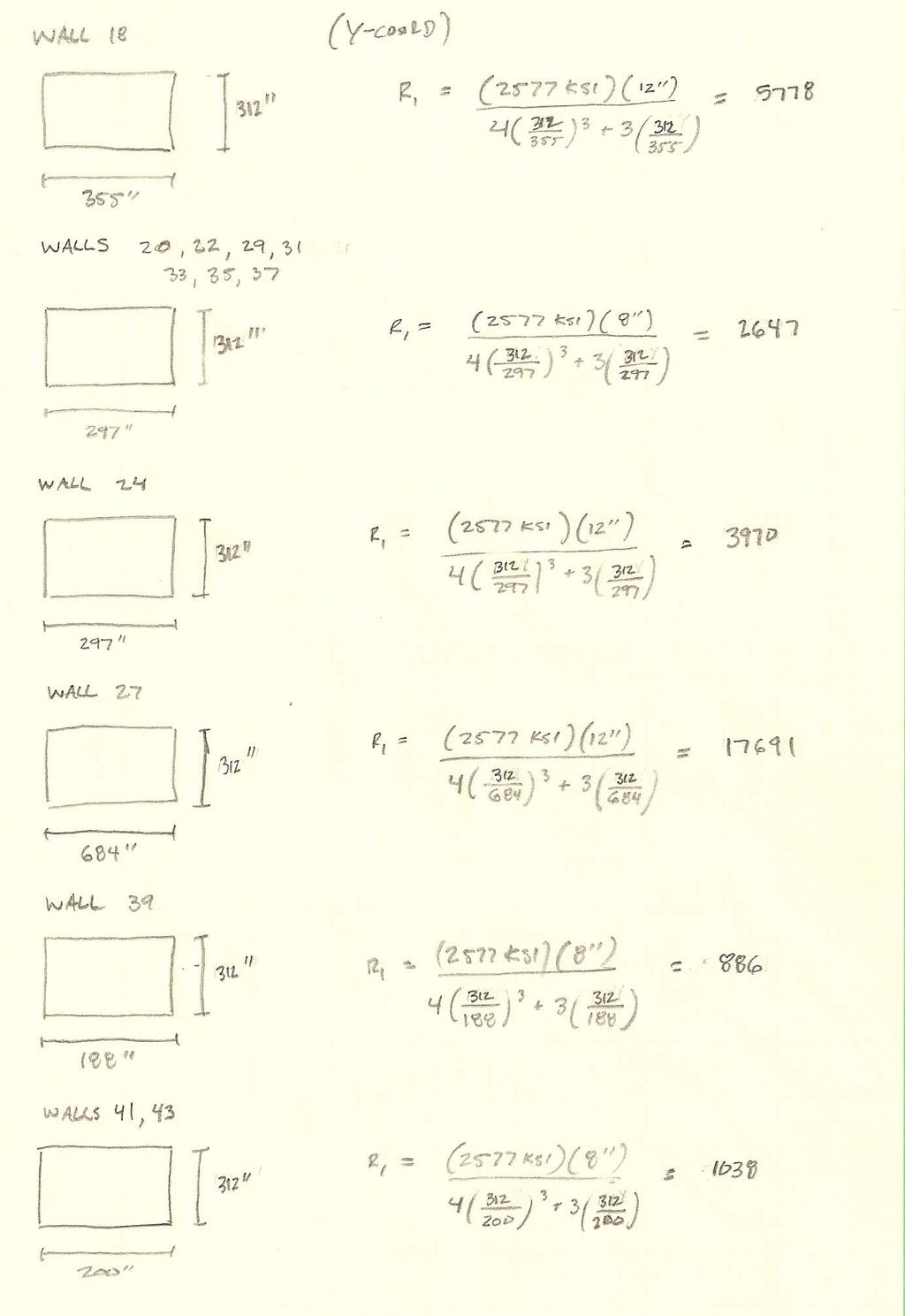
23 Individual wall rigidities are shown in Tables in Appendix C. The rigidities of each wall were calculated using the following equation: Using the rigidities it is possible to determine the center of rigidity of each floor using the following equation: Since the building is made up of two rectangles, it becomes simpler to determine the center of mass of the building. The center of mass does not vary from floor to floor and is consistent throughout the building. Along with the center of mass, the center of rigidity values can be found in Table 1.7, which is a comparison of the ETABS results and hand calculations. The values differ because of the assumptions made for each calculation. The hand calculations for rigidity only account for the shear walls, whereas the ETABS model takes into account the floor diaphragms as well. The ETABS results will be used whenever the center of mass or center of rigidity is needed to complete remaining calculations. Detailed calculations can be found in Appendix C. ETABS vs. Hand Calculation Comparison Center of Rigidity Center of Mass ETABS Calculation Hand Calculation ETABS Calculation X Y X Y X Y Floor Floor Floor Floor Floor Table 1.7: ETABS vs. Hand Calculations 22
24 Relative Stiffness With the rigidity of the walls determined, the relative stiffness, which is the percentage of lateral force being distributed into each shear wall, can be determined. The relative stiffness will not be consistent throughout the entire height of the building, so each wall on every floor can be found using the following equation: The values for the North/South walls at every floor can be found in Table 1.8, and the values for the East/West walls at every floor can be found in Table 1.9 below. By determining the relative stiffness of each wall, these values can be directly applied to the loads at each floor to determine how much of the load each wall will have to resist. Appendix C shows detailed calculations for the relative stiffness of the individual walls. Relative Stiffness (%) North - South Force Floor 1 Floor 2 Floor 3 Floor 4 Floor 5 Wall Wall Wall Wall Wall Wall Wall Wall Wall Wall Wall Wall Wall Wall Wall Wall Wall Wall Wall Wall Wall Wall Wall Wall Wall Wall Wall Wall Table 1.8: Relative Stiffness in North-South Direction Relative Stiffness (%) East - West Force Floor 1 Floor 2 Floor 3 Floor 4 Floor 5 Wall Wall Wall Wall Wall Wall Wall Wall Wall Wall Wall Wall Wall Wall Wall Wall Wall Wall Wall Wall Wall Wall Wall Wall Table 1.9: Relative Stiffness in East-West Direction *Floor 1 and Floor 5 were not calculated by hand since the layout differs from the other floors. 23
25 Torsion Torsion occurs when the center of rigidity and the center of mass locations do not coincide. Eccentricity, which is the distance between the center of rigidity and center of mass, induces a moment that creates additional forces on the building. The resulting force is the torsional shear. When determining the torsional effects on the CityFlatsHotel, two different types of torsional moments need to be taken into account. According to ASCE 7-05, torsion for rigid diaphragms is the sum of the inherent torsional moment and the accidental torsional moment. The inherent torsional moment, M t, is the caused by the eccentricity between the center of rigidity and center of mass. The lateral force exerted on the building at a specified floor level, times the eccentricity, will give the inherent torsional moment. The accidental torsional moment, M ta, is caused by an assumed displacement of the center of mass, due to the rigidity of the slab. This displacement is equal to 5% of the center of mass dimension each way from the actual location perpendicular to the direction of the applied force. Torsional moments produced can be seen in Tables 1.10 and Detailed calculations can be found in Appendix D. Story Level Factored Lateral Force (k) Overall Building Torsion North/South Direction COR-COM (ft.) M t (ft-k) M ta (ft-k) M t,tot (ft-k) Story Story Story Story Story Total: Table 1.10: Torsion in North/South Direction Story Level Factored Lateral Force (k) Overall Building Torsion East/West Direction COR-COM (ft.) M t (ft-k) M ta (ft-k) M t,tot (ft-k) Story Story Story Story Story Total Table 1.11: Torsion in East/West Direction 24
26 Shear The overall shear force at each level is the combination of direct and torsional shear. Direct shear forces relate to the relative stiffness of the shear walls, whereas the torsional shear forces relate to the torsional moments produced on each floor as a result of the wind or seismic loads. Direct Shear The distribution of the lateral forces among the shear walls at each level is considered the direct shear. These lateral forces are directed through the load path where, the wall with larger shear wall stiffness resists the larger load. Tables 1.12 and 1.13 show the direct shears applied to each wall for each floor level. Detailed calculations for obtaining the direct shear for the North/South and East/West direction may be found in Appendix E. North/South Direct Shear 1.2D+1.6W+1. 0L+0.5L r Roof Floor 5 Floor 4 Floor 3 Floor 2 Force (k) Factored Wall Wall Wall Wall Wall Wall Wall Wall Wall Wall Wall Wall Wall Wall Wall Wall Wall Wall Wall Wall Wall Wall Wall Wall Wall Wall Wall Wall Distributed Force (k) Distributed Force (k) East/West Direct Shear 0.9D+1.0E Roof Floor 5 Floor 4 Floor 3 Floor 2 Force (k) Factored Wall Wall Wall Wall Wall Wall Wall Wall Wall Wall Wall Wall Wall Wall Wall Wall Wall Wall Wall Wall Wall Wall Wall Wall Table 1.13: East/West Direct Shear Table 1.12: North/South Direct Shear 25

27 Torsional Shear Since torsion is present in the CityFlatsHotel structure, each shear wall has to resist torsional shear, due to the torsional moments caused on each floor by the eccentricity. The total torsional shear at each wall is dependant on the relative stiffness of each shear wall, where once again, the greater the relative stiffness, the greater the shear force on that wall. To determine the torsional shear, the following equation is used: Where: V tot = Total Story Shear e = eccentricity d i = distance from center of rigidity to shear wall R i = relative stiffness of shear wall J = torsional moment of inertia The torsional shear forces were determined for the shear walls supporting floor 2 and can be found in Table Additional detailed calculations for obtaining the torsional shear can be found in Appendix E. Figure 1.18: Center of Masses 26
28 Factored Story Shear V tot Torsional Shear in Shear Walls Supporting Floor 3 Relative Stiffness R i Distance from COM to COR e (in) Distance from Wall i to COR d i (in) (R i )(d i 2 ) Torsional Shear (k) (k) Wall 1 N/S Wall 3 N/S Wall 4 N/S Wall 6 N/S Wall 8 N/S Wall 10 N/S Wall 12 N/S Wall 13 N/S Wall 14 N/S Wall 16 N/S Wall 17 N/S Wall 19 N/S Wall 21 N/S Wall 23 N/S Wall 25 N/S Wall 26 N/S Wall 28 N/S Wall 30 N/S Wall 32 N/S Wall 34 N/S Wall 36 N/S Wall 38 N/S Wall 40 N/S Wall 44 N/S Wall 45 N/S Wall 47 N/S Wall 49 N/S Wall 51 N/S Wall 2 E/W Wall 5 E/W Wall 7 E/W Wall 9 E/W Wall 11 E/W Wall 15 E/W Wall 18 E/W Wall 20 E/W Wall 22 E/W Wall 24 E/W Wall 27 E/W Wall 29 E/W Wall 31 E/W Wall 33 E/W Wall 35 E/W Wall 37 E/W Wall 39 E/W Wall 41 E/W Wall 42 E/W Wall 43 E/W Wall 46 E/W Wall 48 E/W Wall 50 E/W Wall 52 E/W i)(d 2 i ) = Table 1.14: Torsional Shear 27
29 Shear Strength Check In order to verify if there is sufficient reinforcement in the shear walls, a shear strength check must be performed. According to ACI , the shear strength of a reinforced concrete masonry shear wall can be obtained by the following equation: The shear wall strength checks performed for walls supporting floor 2 can be found in Table Each shear wall was within the capacity determined by the shear strength, which verifies that the masonry reinforcement is adequately designed. Detailed calculations for shear strength can be found in Appendix E. 28
30 Shear Wall Strength Check Supporting Floor 3 Floor Direct Shear Torsional Vertical Spacing Length Thickness Vu (k) (k) Shear (k) Reinforcement (in) (in) (in) A cv (in 2 ) c t n (k) Wall (2) # Wall (2) # Wall (2) # Wall (2) # Wall (2) # Wall (2) # Wall (2) # Wall (2) # Wall (2) # Wall (2) # Wall (2) # Wall (2) # Wall (2) # Wall (2) # Wall (2) # Wall (2) # Wall (2) # Wall (2) # Wall (2) # Wall (2) # Wall (2) # Wall (2) # Wall (2) # Wall (2) # Wall (2) # Wall (2) # Wall (2) # Wall (2) # Wall (2) # Wall (2) # Wall (2) # Wall (2) # Wall (2) # Wall (2) # Wall (2) # Wall (2) # Wall (2) # Wall (2) # Wall (2) # Wall (2) # Wall (2) # Wall (2) # Wall (2) # Wall (2) # Wall (2) # Wall (2) # Wall (2) # Wall (2) # Wall (2) # Wall (2) # Wall (2) # Wall (2) # Table 1.15: Shear Strength Check 29
31 Drift and Displacement Overall drift of nonstructural members is a concern and should be limited as much as possible. The drift is a serviceability consideration that relates the rigidity of each of the shear walls. As the height of the building increases building drift and deformation become larger factors. According to IBC 2006, wind load drift is limited to an allowable drift of = l/400, whereas seismic drift is limited to an allowable drift of = 0.02hsx. Wind controls the drift in the North/South direction of the CityFlatsHotel, while seismic forces control the drift in the East/West direction. The allowable building drift limit for CityFlatsHotel is: limit = 1852 / 400 = 4.63 Each floor is examined independently to determine an approximate story displacement and story drift. In order to determine the overall building drift, the displacement and story drift of each individual floor is summed. The following equation was used to determine the overall building drift: cantilever = flexural + shear Detailed hand calculations used to determine the drift and displacement can be found in Appendix F. Table 1.16 is a summary of story displacement for wall 10. Floor Supported Lateral Force (k) E c (ksi) E r (ksi) I (in 4 ) Thickness (in) Wall 10 Story Displacement Length (in) Height (in) flex shear Story Dissplacement (in) Story Drift (in) Allowable Story Drift (in) Roof Floor Floor Floor Floor Total Wall Displacement (in) Table 1.16: Example Story Displacement 30
32 Overturning Moments Due to the lateral forces and moments that are exerted on the building, overturning affects must be taken into consideration. These overturning moments are a concern because of the impact they potentially have on the foundation system. A calculation must be conducted to determine if the building dead load is sufficient to resist any impact of the overturning moments. As shown in Table 1.17, total overturning moments are provided due to wind and seismic loads. In order to verify that the dead load is adequate to resist overturning moments due to wind and seismic loads, the stresses due to the lateral loads are compared to the stresses due to the building selfweight. The analysis results of the CityFlatsHotel conclude that stresses due to lateral loads are minimal compared to the dead load stresses, therefore the foundation experiences minimal overturning effects. However, a force will be present along the perimeter of the building due to the moment exerted on the structure. Detailed calculations for overturning moments are in Appendix G. Floor Height Above Ground Z (ft) Story Height (ft) Overturning Moments Lateral Force F x (k) N/S Wind Forces Total Moment M x (ft-k) E/W Seismic Forces Lateral Force F x (k) Total Moment M x (ft-k) Roof Floor Floor Floor Floor Floor Total = Table 1.17: Overturning Moments 31
33 Conclusion Creating a model in ETABS and completing a thorough investigation of the lateral resisting system, by applying wind and seismic loads, provided a basic analysis of the CityFlatsHotel s existing lateral system. By evaluating the basic load combinations as defined by ASCE 7-05, it was determined through ETABS that the load case 1.2D+1.6W+1.0L+0.5L r controls in the North/South direction, and 0.9D+1.0E controls in the East/West direction. These results are due to the overall shape, size, and layout of CityFlatsHotel. In order to apply the proper lateral loads to the structure it was necessary to revise the wind and seismic analysis performed in Technical Report 1. These corrected loads were applied to the ETABS model, which was used as a reference to verify that the model and hand calculations were providing similar and reasonable results. It was found that the center of rigidity values differed between the ETABS model and hand calculations. This is because the hand calculations only take into account the shear walls, and ignoring the floor diaphragm, which is included in the computer model analysis. As a result the values from the computer model for center of rigidity and center of mass were used in the remaining calculations. Torsion was present in the building due to the eccentricity between the center of mass and rigidity. This created a torsional shear in addition to the direct shear, which was already acting on the shear walls. A shear strength check was performed to determine if the reinforcement and thickness of the shear walls was designed adequately to resist the total shear. The overall building drift was determined by ETABS and by hand calculations to be within the allowable code limitations. However, because the calculations neglect that the fact that the interior core shear walls act as a unit, the drifts and displacements can only be considered an approximation. Overturning moments were present due to the lateral loads on the building, but a stress check determined that the self-weight of the building resists the overturning moments and the impact on the foundations due to overturning is minimal. These checks conclude that the shear walls designed are adequate to resist the load combinations applied to the CityFlatsHotel. 32

34 Appendix A: Plans Foundation Plan 33
35 First Level Framing Plan 34
36 Second Level Framing Plan 35
37 Third Level Framing Plan 36
38 Fourth Level Framing Plan 37
39 Fifth Level Framing Plan 38
40 Sixth Level (Upper Roof) Framing Plan 39

41 Appendix B: Loads Wind Loads 40

42 41

43 42
44 Seismic Loads Example of Floor Weights Found Seismic Force Resisting System: Second Floor Approximate Area (SF) Floor to Floor Height (ft.) 12 Walls Perimeter (ft.) Height (ft.) Unit Weight (PSF) Weight (k) Superimposed Partitions (PSF) 15 MEP (PSF) 10 Finishes (PSF) 5 Weight (k) 366 Slab Thickness (in.) 8 Unit Weight (PSF) 80 Weight (k) 976 Columns Shape Quantity Weight Column (PLF) Height (ft.) Weight (k) HSS 8x8x3/8" W24x Totals Beams Shape Quantity Weight Beam Length Weight (k) (PLF) (ft.) W8x W8x W12x W12x W18x W24x C 4x Totals Total Weight of Floor (k) Total Weight of Floor (PSF)
45 44

46 45

47 46

48 Appendix C: Load Distribution Rigidity and Relative Stiffness 47

49 48
50 49

51 50

52 51

53 52

54 53

55 Appendix D: Torsion 54
56 Appendix E: Shear 55

57 56

58 Appendix F: Drift and Displacement 57

59 58

60 59

61 Appendix G: Overturning Moments 60
October 19, The Pennsylvania State University. Hunter Woron Structural. Professor M. Kevin Parfitt
 October 19, 2011 Hunter Woron Structural Professor M. Kevin Parfitt The Pennsylvania State University Table of Contents Executive Summary.. 2 Introduction 3 Structural Systems. 4 Foundation.. 4 Superstructure
Technical Report #3. Matthew R Peyton
 Technical Report #3 This Document is Technical Report #3 for 5th year senior thesis in the Architectural Engineering Departments at The Pennsylvania State University. In this report the existing reinforced
Cambria Suites Hotel. Pittsburgh, PA. Technical Report 3. Lateral System Analysis and Confirmation Design
 Cambria Suites Hotel Pittsburgh, PA Technical Report 3 Lateral System Analysis and Confirmation Design November 29, 2010 Table of Contents Table of Contents 2 Executive Summary..4 Introduction: Cambria
MOUNTAIN STATE BLUE CROSS BLUE SHIELD HEADQUARTERS
 MOUNTAIN STATE BLUE CROSS BLUE SHIELD HEADQUARTERS PARKERSBURG, WEST VIRGINIA DOMINIC MANNO STRUCTURAL OPTION FACULTY CONSULTANT: DR. ANDRES LEPAGE Technical Report 3 11-21-08 TABLE OF CONTENTS TABLE OF
OVERALL STRUCTURAL SYSTEM
 EXECUTIVE SUMMARY The at the Pittsburgh International Airport, PA, is a 275,000 square foot multi-use building located directly adjacent to the airport s landside terminal. The building consists of an
Technical Report #1. Matthew R Peyton
 Technical Report #1 This Document is Technical Report #1 for 5th year senior thesis in the Architectural Engineering Departments at The Pennsylvania State University. This Report will include structural
Danielle Shetler - Structural option Courtyard by Marriott Lancaster, PA
 Structural Analysis Overview: During the structural analysis of the in Lancaster, Pa, a redesign of the lateral and gravity system from masonry bearing and shear walls to a staggered truss system was performed.
[TECHNICAL REPORT 3] Lateral System Analysis
![[TECHNICAL REPORT 3] Lateral System Analysis](/thumbs/96/126531717.jpg "[TECHNICAL REPORT 3] Lateral System Analysis") Science Center Research Park 3711 Market St. The Pennsylvania State University Department of Architectural Engineering Senior Thesis 2009-2010 Prepared by: November 30, 2009 [TECHNICAL REPORT 3] Lateral
Science Center Research Park 3711 Market St. The Pennsylvania State University Department of Architectural Engineering Senior Thesis 2009-2010 Prepared by: November 30, 2009 [TECHNICAL REPORT 3] Lateral
1000 CONTINENTAL SQUARE
 1000 CONTINENTAL SQUARE KING OF PRUSSIA, PENNSYLVANIA Carter Davis Hayes Structural Option January 13, 2008 Advisor: Dr. Hanagan TABLE OF CONTENTS TABLE OF CONTENTS... 2 EXECUTIVE SUMMARY... 3 I. STRUCTURAL
Structural Redesign Gravity System
 Redesign Gravity System Design Considerations A composite floor system was used for this design to maximize the efficiency of the material being used. This type of system requires less material and provides
School of Engineering and Applied Science Building Miami University, Oxford, OH Technical Assignment 3 December 3, 2007
 School of Engineering and Applied Science Building Miami University, Oxford, OH Technical Assignment 3 December 3, 2007 Jonathan Kirk AE 481W Senior Thesis The Pennsylvania State University Faculty Advisor:
TECHNICAL REPORT 1. Structural Concepts / Structural Existing Conditions. Penn State Hershey Medical Center Children s Hospital. Hershey, Pennsylvania
 TECHNICAL REPORT 1 Structural Concepts / Structural Existing Conditions Penn State Hershey Medical Center Children s Hospital Matthew V Vandersall The Pennsylvania State University Architectural Engineering
Point Pleasant Apartments Point Pleasant, NJ Ryan P. Flynn Structural Option Faculty Consultant: Dr. Hanagan
 Point Pleasant Apartments Point Pleasant, NJ Ryan P. Flynn Structural Option Faculty Technical Report #3: Lateral System Analysis and Confirmation Design Table of Contents Introduction... 3 Executive Summary...
David A. Walenga Technical Assignment #1
 Executive Summary Contained in this report is design information related to the structural system of the Residence Inn by Marriot located in Stamford, Connecticut. Specifically, this report covers: code
Technical Assignment 3 December 3, 2007
 Technical Assignment 3 December 3, 2007 101 Eola Drive, Orlando, FL Justin Raducha Pennsylvania State University Faculty Advisor: M. Kevin Parfitt Table of Contents Table of Contents... 2 Executive Summary...
Rutgers University Law School Building Addition and Renovation Camden, NJ
 Building Addition and Renovation Camden, NJ Technical Assignment 1 October 5, 2007 Nathan E. Reynolds Structural Option Senior Thesis The Pennsylvania State University Faculty Consultant: Professor M.
Technical Report #3: Lateral System Analysis. Executive Summary
 ERIC MUELLER STRUCTURAL OPTION ADVISOR DR. LEPAGE AE 481W DECEMBER 19, 2006 555 12 TH STREET OAKLAND, CALIFORNIA Technical Report #3: Lateral System Analysis Executive Summary 555 12 th Street is a 21
Structural Technical Report 1 Structural Concepts / Structural Existing Conditions Report
 Michael A. Troxell Structural Option Advisor: Professor Parfitt College of Business Administration Oct. 5, 2005 Structural Technical Report 1 Structural Concepts / Structural Existing Conditions Report
FAIRFIELD INN & SUITES, MARRIOT PITTSBURGH, PA
 1/11/2010 THESIS PROPOSAL FAIRFIELD INN & SUITES, MARRIOT PITTSBURGH, PA Advisor: Dr. Ali Memari Structural Option TABLE OF CONTENTS Table of Contents 2 Executive Summary...3 Introduction: Fairfield Inn
1000 CONNECTICUT AVENUE
 1000 CONNECTICUT AVENUE Gea Johnson Structural Option Faculty Advisor: Dr. Hanagan September 23, 2011 Revised: December 16, 2011 Washington DC Technical : Existing Conditions Table of Contents Executive
G.Muttrah Commercial & Residential Complex Muscat, Sultanate of Oman
 G.Muttrah Commercial & Residential Complex Muscat, Sultanate of Oman Technical Report III Samir Al-Azri Structural Option Consultant: December 1 st, 2009 Page 1 Table of Contents I. Executive summary.
TECHNICAL REPORT III. University Academic Center. Eastern USA. Alexander Altemose. Structural Option. Advisor: Thomas E. Boothby
 TECHNICAL REPORT III University Academic Center Eastern USA Alexander Altemose Structural Option Advisor: Thomas E. Boothby November 12, 2012 Table of Contents Executive Summary 3 Introduction 4 Structural
Technical Assignment #3 November 15, 2004 Lateral System Analysis and Confirmation Design
 Executive Summary Technical Assignment #3 November 15, 2004 Lateral System Analysis and Confirmation Design The Food Science Building in State College, Pennsylvania is a four story above ground steel composite
Executive Summary...2 Introduction...3 Structural System Overview Buffalo,...4 Foundation...4 Floor System...4 Gravity System...4 Lateral System...
 Table of Contents University at Buffalo CTRC/Incubator Executive Summary...2 Introduction...3 Structural System Overview Buffalo,...4 New York Foundation...4 Floor System...4 Gravity System...4 Lateral
FINAL REPORT. Structural Redesign of Hershey Medical Center Children s Hospital. Penn State Hershey Medical Center Children s Hospital
 FINAL REPORT Structural Redesign of Hershey Medical Center Children s Hospital Penn State Hershey Medical Center Children s Hospital The Pennsylvania State University Architectural Engineering Adviser:
Letter of Transmittal
 Letter of Transmittal November 17, 2014 Ali Said Structural Thesis Advisor The Pennsylvania State University aus59@psu.edu Dear Doctor Said, The following technical report fulfills the fourth Technical
HIGH RISE CONDO SOHO, NEW YORK, NY
 HIGH RISE CONDO SOHO, NEW YORK, NY TECHNICAL ASSIGNMENT 1 October 5, 2006 Joseph The Pennsylvania State University Structural Option Faculty Advisor: Andres Lepage TABLE OF CONTENTS TABLE OF CONTENTS 2
Executive Summary. Greg Kochalski. JW Marriott, Grand Rapids, MI
 Executive Summary JW Marriott, Grand Rapids, MI November 21, 2006 Greg Kochalski Structural Advisor: Boothby The JW Marriott is a 24 story hotel currently under construction in Grand Rapids, Michigan and
Imaging Research Building
 University of North Carolina s Imaging Research Building Technical Report 3, LEED AP Structural Option Consultant- Dr. Thomas Boothby December 2, 2009 Table of Contents Executive Summary... 3 Introduction...
Hilton Baltimore Convention Center Hotel Western Podium
 Hilton Baltimore Convention Center Hotel Western Podium CHRIS SIMMONS Structural Option Faculty Consultant: Dr. Ali M. Memari Technical Report 1 TABLE OF CONTENTS EXECUTIVE SUMMARY. Page 3 INTRODUCTION..
John Jay College Expansion Project
 Technical Report #3 Michael Hopper Mike AE Consultant: Dr. Lepage [Type the company name] November 21 st, 2008 Technical Report #3 Table of Contents Executive Summary.3 Introduction.4 Existing Composite
Structural Technical Report I October 5, 2006 Structural Concepts / Structural Existing Conditions Report
 1 THE ODYSSEY ARLINGTON, VA Aaron Snyder Structural Option Advisor: M. Kevin Parfitt, PE Structural Technical Report I October 5, 2006 Structural Concepts / Structural Existing Conditions Report Executive
40 Bond New York, NY. Technical Report 3
 40 Bond Technical Report 3 Samantha D'Agostino Structural Option Consultant - Dr. Thomas Boothby November 21, 2008 Table of Contents Executive Summary... 3 Introduction 4 Architectural Design Concepts.
Executive Summary Building Description: Introduction... 13
 Table of Contents Executive Summary... 2 Building Description:... 2 Report Summary:... 2 Introduction... 3 Building Description:... 3 Current Framing Layout... 4 Report Topics:... 4 Loads and Load Cases...
Xyston Inn. NY. Proposal. Xiaodong Jiang. Structure Option. Advisor: Dr. Linda Hanagan
 Proposal Xiaodong Jiang Structure Option Advisor: Dr. Linda Hanagan December 12, 2014 Executive Summary Xyston Inn is a 17-story hotel building that will be located in Brooklyn, New York. The design of
Hyatt Place North Shore. Pittsburgh, PA T. Technical Assignment #1. Kyle Tennant. Kyle Tenn. Structural (IP) [Type the document subtitle]
![Hyatt Place North Shore. Pittsburgh, PA T. Technical Assignment #1. Kyle Tennant. Kyle Tenn. Structural (IP) [Type the document subtitle]](/thumbs/85/92906985.jpg "Hyatt Place North Shore. Pittsburgh, PA T. Technical Assignment #1. Kyle Tennant. Kyle Tenn. Structural (IP) [Type the document subtitle]") Technical Assignment #1 Hyatt Place North Shore [Type the document subtitle] T Kyle Tenn Kyle Tenn Kyle Tennant Structural (IP) Dr. Ali Memari O c t o b e r 4 2 0 1 0 Table of Contents I. Executive Summary
Technical Assignment #1 Hyatt Place North Shore [Type the document subtitle] T Kyle Tenn Kyle Tenn Kyle Tennant Structural (IP) Dr. Ali Memari O c t o b e r 4 2 0 1 0 Table of Contents I. Executive Summary
Xyston Inn. NY. Proposal. Xiaodong Jiang. Structure Option. Advisor: Dr. Linda Hanagan
 Proposal Xiaodong Jiang Structure Option Advisor: Dr. Linda Hanagan December 12, 2014 Executive Summary Xyston Inn is a 17-story hotel building that will be located in Brooklyn, New York. The design of
Belmont Executive Center; Building A
 Nicholas L. Ziegler: Structural Advisor: Professor M. Kevin Parfitt December 1, 2009 1 Table of Contents Executive Summary...3 Introduction...3 Structural System...4 Foundation System... 4 Column System...
STRUCTURAL TECHNICAL REPORT 1
 Technical Report 1 Page 1 David Lee AE 481W Structural Option Advisor: Andres Lepage URS Office Building October 5, 2006 STRUCTURAL TECHNICAL REPORT 1 Structural Concepts / Structural Existing Conditions
111 MORGAN ST. Ryan Friis
 Technical Report No. 1 September 30, 2002 Executive Summary: 111 Morgan St. is a 9 story cast-in-place concrete condominium building being constructed in Chicago, Illinois. The building s floor system
Structural System. Design Criteria Fire Resistance Concrete designed for 2 HR rating (worst case) Geotechnical Report Allowable Bearing Capacity
 Geotechnical Report Allowable Bearing Capacity") System Codes and Criteria Design Codes and Standards The design code used is the Wisconsin Administrative Code along with the State of Wisconsin Department of Commerce-Safety & Buildings Chapters Comm
System Codes and Criteria Design Codes and Standards The design code used is the Wisconsin Administrative Code along with the State of Wisconsin Department of Commerce-Safety & Buildings Chapters Comm
Table of Contents 2. Structural Systems.4 Foundations.4 Floor System...4 Columns..5 Lateral System...5
 WISCONSIN PLACE RESIDENTIAL TECHNICAL ASSIGNMENT 1 OCTOBER 5, 2007 KURT KRASAVAGE THE PENNSYLVANIA STATE UNIVERSITY STRUCTURAL OPTION FACULTY ADVISOR: DR. ALI MEMARI Table of Contents Table of Contents
Kevin Wigton Structural Option. Technical Report III. Simmons College School of Management, Boston, Ma
 Kevin Wigton Structural Option Technical Report III Simmons College School of Management, Boston, Ma Advisor: Professor Parfitt 12/1/2009 Table of Contents Executive Summary: Technical Report III... 3
TECHNICAL REPORT 3. S.T.E.P.S. Building. Lehigh University. Bethlehem, PA. Technical Report 3. Lateral System Analysis
 TECHNICAL REPORT 3 S.T.E.P.S. Building Lehigh University Lateral System Analysis Bethlehem, PA, Structural Option Faculty Advisor: Linda Hanagan September 17 th, 2012 0 Table of Contents 1 Executive Summary
Simplified Building Schematic for Typical Floor (Levels 9 through 22):
:") Introduction to Structural System Simplified Building Schematic for Typical Floor (Levels 9 through 22): Key: - Tower Columns - Tower Shear Walls - Parking Garage Columns - Parking Garage Shear Walls Solid
Introduction to Structural System Simplified Building Schematic for Typical Floor (Levels 9 through 22): Key: - Tower Columns - Tower Shear Walls - Parking Garage Columns - Parking Garage Shear Walls Solid
Park Potomac Office Building E
 Technical Assignment 1 Kyle Wagner (IP) AE Consultant: Professor Kevin Parfitt October 05, 2009 Table of Contents I. Executive Summary 3 II. Introduction... 4 III. Structural System Overview..... 4 Foundation
Farquhar Park Aquatic Center. York, PA
 Technical Report #1 Jason Kukorlo Consultant: Dr. Linda M. Hanagan October 5, 2009 1 TABLE OF CONTENTS I. Executive Summary.3 II. III. IV. Introduction..4 Structural System Overview Foundation...6 Superstructure..7
Lateral System Analysis and Confirmation Design November 15, 2004
 Jonathan Hill Structural AE Faculty Consultant Dr. Hanagan Lynde and Harry Bradley School of Technology & Trade Milwaukee, Wisconsin Lateral System Analysis and Confirmation Design November 15, 2004 Executive
ECMC Skilled Nursing Facility
 ECMC Skilled Nursing Facility 462 Grider Street Buffalo, NY 14215 Brian Brunnet Structural Option AE 482 Senior Thesis Dr. Ali Memari Presentation Outline Project Background Building Statistics: Location:
Technical Report 1. Kingstowne Section 36A 5680 King Center Drive Kingstowne, VA James Chavanic. Structural Option. Advisor: Dr.
 Technical Report 1 Rendering provided by DCS Design 5680 King Center Drive Kingstowne, VA 22315 Advisor: Dr. Boothby September 17, 2012 TABLE OF CONTENTS Executive Summary 3 Building Introduction 4 Structural
Technical Report #1. Indiana Regional Medical Center Indiana, PA. Cody A. Scheller. Structural Concepts & Existing Conditions Report
 Technical Report #1 Technical Report #1 Structural Concepts & Existing Conditions Report Indiana Regional Medical Center Cody A. Scheller The Pennsylvania State University Architectural Engineering Faculty
Alexis Pacella Structural Option Dr. Schneider Lexington II, Washington D.C. Technical Report #3 November 21,
 1 Executive Summary: Lateral System Analysis and Confirmation Design is an depth look at the lateral system of Lexington II and the loads of which it must carry. The structural system of Lexington II is
Technical Report 1. Seneca Allegany Casino Hotel Addition. Salamanca, NY
 Technical Report 1 Seneca Allegany Casino Hotel Addition Salamanca, NY Nicholas Reed Structural Option Advisor: Prof. Parfitt Executive Summary The purpose of this technical report was to analyze the existing
90% Design Submittal Structural Calculations Parking Garage CDRL
 NORTH METRO RAIL LINE PROJECT Thornton Crossroads at 104 th Avenue Station 90% Design Submittal Structural Calculations Parking Garage CDRL 03-037.11.06 June 2, 2017 Prepared by: Regional Rail Partners
William W. Wilkins Professional Building Columbus, Ohio
 William W. Wilkins Professional Building Columbus, Ohio Technical Assignment 1 October 5, 2006 Michelle Structural Option AE 481W Senior Thesis Faculty Advisor: Dr. Boothby Table of Contents Executive
Southwest Housing, Arizona State University
 Prepared by KSENIA TRETIAKOVA Structural Option 01.09.2012 Architectural Engineering Pennsylvania State University 2012 Southwest Housing, Arizona State University Technical Report #3 Lateral System 01.09.2012
40 Bond New York, NY. Technical Report 1
 40 Bond Technical Report 1 40 Bond is a luxury residential building located in the NoHo neighborhood of Manhattan. The architecture and function of this building greatly impacted the design and development
FAIRFIELD INN & SUITES, MARRIOT PITTSBURGH, PA
 4/7/2010 SENIOR THESIS FINAL REPORT FAIRFIELD INN & SUITES, MARRIOT PITTSBURGH, PA Advisor: Dr. Ali Memari Structural Option P a g e 2 TABLE OF CONTENTS Acknowledgements.. 5 Executive Summary...6 Building
Technical Report #2. Matthew R Peyton
 Technical Report #2 This Document is Technical Report #2 for 5th year senior thesis in the Architectural Engineering Departments at The Pennsylvania State University. This Report is to prepare a study
Structural Technical Report 1 Structural Concepts / Existing Conditions
 Chris Shelow Structural Advisor: M. Kevin Parfitt Koshland Integrated Natural Science Center 10/05/05 AE 481W Structural Technical Report 1 Structural Concepts / Existing Conditions Executive Summary The
Technical Report 1. Residence Inn By Marriott. Structural Option September 29, Existing Conditions / Structural Concepts.
 Katie Ritter Advisor: Dr. Ali Memari Structural Option September 29, 2008 Technical Report 1 Existing Conditions / Structural Concepts Residence Inn By Marriott Norfolk, Virginia 1 P age TABLE OF CONTENTS
Fairfield Inn and Suites Pittsburgh, PA
 Existing Building Information Presentation Outline Construction Management Breadth Study Existing Building Information Location: Downtown Pittsburgh 228 Federal St, Building Statistics: Occupancy - Hotel
Structural Technical Report 1 Structural Concepts/ Structural Existing Conditions Report
 Kelly M. Sadusky The Food Science Building Oct. 6, 2004 Professor Parfitt University Park, PA Structural Option Executive Summery: Structural Technical Report 1 Structural Concepts/ Structural Existing
Arlington, Virginia December 3, 2007 TECHNICAL REPORT III LATERAL SYSTEM ANALYSIS AND CONFIRMATION DESIGN
 TECHNICAL REPORT III LATERAL SYSTEM ANALYSIS AND CONFIRMATION DESIGN EXECUTIVE SUMMARY The is the practice facility for the NHL franchise, Washington Capitals. It is located in Arlington, Virginia just
Design Criteria. Analysis and Design of a High Rise Steel Braced Frame Core 22
 Analysis and Design of a High Rise Steel Braced Frame 22 Design Criteria Design Methodology The design of a high rise lateral force resisting system and gravity system poses itself as a daunting and cumbersome
Trump Taj Mahal Hotel
 Trump Taj Mahal Hotel Atlantic City, New Jersey Thesis Proposal Prepared By: Stephen Reichwein, Structural Option Faculty Advisor: Dr. Andres Lepage The Pennsylvania State University Department of Architectural
Visteon Village Corporate Center
 Visteon Village Corporate Center Van Buren Township, MI Technical Assignment #1 Jamison Morse Structural Option Advisor: Dr. Andres Lapage Jamison Morse Structural Option Visteon Village Center Advisor:
HIGH RISE CONDO SOHO, NEW YORK, NY
 HIGH RISE CONDO SOHO, NEW YORK, NY TECHNICAL ASSIGNMENT 3 November 21, 2006 Joseph Mugford The Pennsylvania State University Structural Option Faculty Advisor: Andres Lepage TABLE OF CONTENTS TABLE OF
Boyds Bear Country Pigeon Forge, TN
 Technical Report 3 Lateral System Analysis and Confirmation Design Executive Summary:, located in Pigeon Forge, Tennessee, is designed as a multifunctional space and tourist attraction for Boyds Collections
Technic. Photo Courtesy of. Ryan
 ASHA National Office Rockville, MD Technic cal Report III Photo Courtesy of Boggs & Partners Architects Ryan Dalrymple Structures Option Table of Contents Executive Summary. Page 3 Introduction... Page
Boyds Bear Country Pigeon Forge, TN
 Technical Report 1 Structural Concepts / Structural Existing Conditions Report Executive Summary:, located in Pigeon Forge, Tennessee, is designed as a multifunctional space and tourist attraction for
Structural Option Indiana Regional Medical Center Indiana, PA
 West View of IRMC Southeast View of IRMC Structural Option Indiana Regional Medical Center Indiana, PA West View of IRMC Southeast View of IRMC Arial View of IRMC Project Information N Location: Occupancy
NATIONAL HARBOR BUILDING M OXON HILL, MARYLAND. Ryan Sarazen Structural Option Technical Report 3 Faculty Consultant: Dr.
 NATIONAL HARBOR BUILDING M OXON HILL, MARYLAND Ryan Sarazen Structural Option Technical Report 3 Faculty Consultant: Dr. Andres Lepage Table of Contents Executive Summary.. 3 Structural Systems Overview...
Hilton Baltimore Convention Center Hotel Western Podium
 Hilton Baltimore Convention Center Hotel Western Podium CHRIS SIMMONS Structural Option Faculty Consultant: Dr. Ali M. Memari Technical Report 2 TABLE OF CONTENTS EXECUTIVE SUMMARY. Page 3 INTRODUCTION..
TECHNICAL REPORT III LATERAL STRUCTURAL SYSTEM ANALYSIS
 TECHNICAL REPORT III LATERAL STRUCTURAL SYSTEM ANALYSIS Chris Vanaskie Structural Peninsula Regional Medical Center Salisbury, MD January 10, 2009 TABLE OF CONTENTS Executive Summary... 3 Introduction...
Letter of Transmittal
 Letter of Transmittal Date: October 17, 2014 To: Dr. Linda Hanagan From: Xiaodong Jiang Dear Dr. Hanagan, This is Xiaodong Jiang, This following report was submitted for Technical Report 3 for AE 481 W.
Traci Peterson Option: Structural Faculty Consultant: Memari. Executive Summary
 1 Traci Peterson Option: Structural Faculty Consultant: Memari The Del Monte Center at The North Shore Pittsburgh, PA Structural Technical Report 3 Lateral System Analysis and Confirmation Design Date
Weill Cornell Medical Research Building 413 E. 69 th Street New York, NY
 Weill Cornell Medical Research Building 413 E. 69 th Street New York, NY Structural Option Technical Report 1 9/23/11 Table of Contents Executive Summary..3 Introduction.4 Structural Systems...5 Foundation
Lateral System Analysis and Confirmation Design
 Andrew Covely Structural Dr. Linda Hanagan The Helena New York City, NY November 15, 2004 Pictures courtesy of Fox & Fowle Architects Lateral System Analysis and Confirmation Design Executive Summary This
REVISED PROPOSAL. University Academic Center. Eastern USA. Alexander Altemose. Structural Option. Advisor: Thomas E. Boothby
 REVISED PROPOSAL University Academic Center Eastern USA Alexander Altemose Structural Option Advisor: Thomas E. Boothby January 11, 2013 Table of Contents Executive Summary 3 Introduction 4 Structural
WESTINGHOUSE ELECTRIC COMPANY CORPORATE HEADQUARTERS CRANBERRY, PA
 WESTINGHOUSE ELECTRIC COMPANY CORPORATE HEADQUARTERS CRANBERRY, PA Technical Assignment 3 November 21, 2008 Advisor: Dr. Linda Hanagan Page 2 of 57 TABLE OF CONTENTS EXECUTIVE SUMMARY... 3 INTRODUCTION...
Structural Design Engineers 120 Montgomery Street, Suite 1410 San Francisco, California / Fax 415/
 120 Montgomery Street, Suite 1410 San Francisco, California 94104 415/781-1505 Fax 415/781-2718 sde@sdesf.com Rajendra Sahai, SE Principal John W. Laws, SE Principal Steven Lepisto, SE Principal STRUCTURAL
OF THREE NEW BUILDINGS BEING CONSTRUCTED TO REPLACE THE EXISTING COMPLEX. THE FLOOR SYSTEM OF GEORGE READ HALL IS A HAMBRO COMPOSITE SYSTEM
 EXECUTIVE SUMMARY: GEORGE READ HALL IS A FIVE STORY DORMITORY ON THE UNIVERSITY OF DELAWARE S CAMPUS. EMCOMPASSING 129,000 SQUARE FEET, IT IS THE LARGEST OF THREE NEW BUILDINGS BEING CONSTRUCTED TO REPLACE
Thesis Proposal. La Jolla Commons Phase II Office Tower San Diego, California. December 13, 2013
 Thesis Proposal December 13, 2013 La Jolla Commons Phase II Office Tower San Diego, California Alyssa Stangl Structural Option Advisor: Dr. Linda Hanagan Table of Contents Executive Summary... 3 Purpose
Johns Hopkins Graduate Student Housing. Thesis Proposal. 929 North Wolfe Street Baltimore, Maryland Brad Oliver Structural Advisor: Professor Memari
 Johns Hopkins Graduate Student Housing 929 North Wolfe Street Brad Oliver Structural Advisor: Professor Memari 12/09/2011 Table of Contents Executive Summary -... 3 Introduction... 4 Structural Systems...
LIFE SCIENCES BUILDING STRUCTURAL CONCEPTS AND EXISTING CONDITIONS
 Structural Technical Report 1 LIFE SCIENCES BUILDING STRUCTURAL CONCEPTS AND EXISTING CONDITIONS Prepared for: Dr. Aly M. Said Dr. Thomas Boothby Professor Kevin Parfitt Dr. Charles D. Cox Prepared by:
Brent Ellmann Structural Option 200 Minuteman Park, Andover, MA Structural Consultant: Dr. Hanagan
 Brief Building Overview: 200 Minuteman Park stands as a 200,000 square foot Class A office building in Andover, Massachusetts, worth roughly $15,000,000. Although the building has a large square footage,
Franklin Square Hospital Center Patient Tower
 Thomas Weaver Structural Option Franklin Square Hospital Center Patient Tower Baltimore, MD Thomas Weaver Structural Option AE 481W Senior Thesis Consultant: Professor M. Kevin Parfitt 12/14/2009 Page
Butler Health System New Inpatient Tower Addition/Remodel. Dr. Ali Memari Technical Report #1. Architects Rendering. Technical Report #1
 Dr. Ali Memari Technical Report # Architects Rendering Technical Report # Due October 5 th, 2009 Dr. Ali Memari Technical Report # Table of Contents I. Executive Summary 3 II. Introduction 4 III. Structural
Pennsylvania College Of Technology Dauphin Hall Williamsport, Pennsylvania
 Pennsylvania College Of Technology Dauphin Hall Williamsport, Pennsylvania Aubert Ndjolba Structural Option AE Senior Thesis- 2011 Thesis Advisor: Dr. Boothby Existing Building Overview Introduction Existing
Global Village Rochester Institute of Technology Rochester, New York
 Presentation Outline Welcome Introduction Architecture Existing Structure Problem Statement Arch. Breadth Structural Depth Conclusion Questions Global Village Rochester Institute of Technology Rochester,
Thesis Proposal. Matthew R Peyton
 This Document is for 5th year senior thesis in the Architectural Engineering Departments at The Pennsylvania State University. S t r u c t u r a l O p t i o n P r o f e s s o r B e h r H o s p i t a l
Third Avenue New York, NY. Structural Concepts/ Structural Existing Conditions Report September 30, Michelle L.
 Executive Summary The structural design of 554-556 Third Avenue is composed of two way concrete slabs supported by a system of columns spanning an average of twenty feet. Lateral loads are resisted by
STRUCTURAL TECHNICAL REPORT 3
 Technical Report 2 Page 1 David Lee AE 481W Structural Option Advisor: Andres Lepage URS Office Building October 27, 2006 STRUCTURAL TECHNICAL REPORT 3 Lateral System Analysis and Confirmation Design Technical
Simplified Building Schematic for Typical Floor (Levels 9 through 22):
:") Introduction to Structural System Simplified Building Schematic for Typical Floor (Levels 9 through 22): Key: - Tower Columns - Tower Shear Walls - Parking Garage Columns - Parking Garage Shear Walls Solid
Introduction to Structural System Simplified Building Schematic for Typical Floor (Levels 9 through 22): Key: - Tower Columns - Tower Shear Walls - Parking Garage Columns - Parking Garage Shear Walls Solid
Earth and Engineering Sciences Building University Park, Pennsylvania
 Executive Summary The Earth and Engineering Sciences building is a 4 story educational and laboratory facility. An additional basement level is located below grade and provides the foundation for the East
John Jay College Expansion Project
 Technical Report #1 Michael Hopper Mike AE Consultant: Dr. Lepage [Type the company name] September 29 th, 2008 Technical Report #1 Table of Contents Executive Summary.3 Introduction.4 Structural System.6
Caitlin Ferrell Structural Option Dr. Boothby, AE Faculty Consultant. Erie Convention Center and Sheraton Hotel
 Caitlin Ferrell Structural Option Dr. Boothby, AE Faculty Consultant Erie Convention Center and Sheraton Hotel Erie, Pennsylvania Technical Report #2: Pro-Con Structural Study of Alternate Floor Systems
GEN*NY*SIS CENTER FOR EXCELLENCE IN CANCER GENOMICS Rensselaer, NY
 Existing Typical Floor Plan The typical floor plan of the Gen*NY*Sis Center for Excellence in Cancer Genomics (CFG) consists of mainly laboratories and offices with an atrium in the center. The hallway
FAIRFIELD INN & SUITES, MARRIOT PITTSBURGH, PA
 10/28/2009 TECHNICAL REPORT II FAIRFIELD INN & SUITES, MARRIOT PITTSBURGH, PA Advisor: Dr. Ali Memari Structural Option TABLE OF CONTENTS Table of Contents 2 Executive Summary...3 Introduction: Fairfield