Holey Silicon as efficient thermoelectric material
|
|
|
- Grace Horton
- 6 years ago
- Views:
Transcription
1 Supporting Information: Holey Silicon as efficient thermoelectric material Jinyao Tang 1, 3*, Hung-Ta Wang 1*, Dong Hyun Lee 4, Melissa Fardy 1, Ziyang Huo 1, Thomas P. Russell 4, 1, 2, 3 Peidong Yang 1 Department of Chemistry, 2 Department of Materials Science and Engineering, University of California, Berkeley, California 94720, USA. 3 Materials Sciences Division, Lawrence Berkeley National Laboratory, Berkeley, California 94720, USA. 4 Department of Polymer Science and Engineering, University of Massachusetts, Amherst, MA 01003, USA. * These authors contributed equally to this work. To whom correspondence should be addressed. p_yang@berkeley.edu 1. Holey Silicon fabrication The HS ribbons used for transport measurements are patterned by optical lithography and then released from SOI substrate (Soitec Inc.) by hydrofluoric acid vapor etching. The SOI wafer consists 100 nm device layer (<100>, Ω cm, phosphorus doped) with 200 nm buried oxide layer. Holey structure is fabricated by DRIE through thin chromium mask (~5 nm) converted from NSL or BCP pattern. Figure S1 shows the schematic of detailed fabrication of 350 nm and 140 nm pitch HS ribbons. 350 nm and 140 nm polystyrene spheres (Bangs laboratories, Inc.) are 1:4 diluted with de-ionized water and subjected to 2 min sonication before coating to insure homogeneous sphere suspension. The substrate is cleaned with piranha for 10 mins and rinsed with de-ionized water followed by N 2 blow-dry. Polystyrene spheres are self-assembled into hexagonal monolayer film via a dip coating process at speed ~4 μm/s in a customized dip coater equipped with isolating shield to prevent disturbing from air flow. Throughout the assembly process, line defects and point defects are sometimes observed mostly due to the non-uniformity of sphere size. Weak oxygen plasma (20 W at ~300 mtorr in the Technics PEII-A plasma system) is then used to etch polystyrene sphere until the desired spacing is obtained. 5 nm chromium film, served as silicon etching
2 mask, is deposited with an e-beam evaporator at 2x10⁻⁶ torr, and the polystyrene spheres are then removed by ultra-sonication in acetone for 5 mins. Silicon etch is performed in a DRIE system, with 600 W (13.56 MHz) applied on coil and 30 W (380 khz) on substrate. After 6 cycles of 5 second passivation plus 6 second etching, 100nm silicon layer is completely etched through. The chromium mask is then removed by soaking the sample in chromium etchant (CR-7s, from Cyantek) for 2 mins at room temperature. A similar chromium mask conversion method is applied to BCP lithography for fabrication of 55 nm pitch HS ribbons, as shown in Figure S2. 55nm-pitch hexagonal structure is patterned on SOI substrate as stated in SI 2. The 5nm chromium mask is deposited onto this holey structured BCP film by e-beam evaporation at 60 degree titling angle. To insure better etching uniformity, sample is further treated with oxygen plasma to thoroughly remove BCP template in order to ensure the silicon is freshly exposed and can be etched away by following DRIE process. SEM is then used to carefully examine the holey structure and >95% etching uniformity of HS is specifically selected for the transport characterizations. 2. Block copolymer (BCP) assembly and characterization Polystyrene-block-poly(4-vinylpyridine) (S4VP) copolymer was purchased from Polymer Source Inc., and used without further purification in this study. Polystyrene homopolymer was synthesized by anionic polymerization. The number average molecular weights (M n ) of polystyrene and poly(4-vinylpyridine) were 51 kg/mol and 18 kg/mol, respectively, and the polydispersity (M w /M n ) of this BCP was The number average molecular weight and the polydispersity of polystyrene homopolymer (hps) were 14.4 kg/mol and 1.03, respectively. The mixture of S4VP and hps with various mixing ratios was dissolved in the mixture of toluene and tetrahydrofuran (70/30, v/v). S4VP thin films (~ 25 nm) were prepared by spin-coating at 2200 rpm on SOI substrates. The films were solventannealed in tetrahydrofuran vapor for 3 hours to induce lateral ordering of BCP microdomains. To generate nanoscopic pores, the surface of S4VP thin films was reconstructed by immersing the substrate into ethanol. To prevent merging holes during a following DRIE process, it is necessary to spread out the separation distance among cylindrical microdomains of P4VP. As introducing hps(14k) into S4VP(69k) thin film, the pitch of cylindrical microdomians of P4VP was
3 gradually increased because hps existed selectively in PS matrix of S4VP thin film. As shown in Figure S3, the pitch in neat S4VP thin film is about 36.1 nm. By adding hps(14k), consequently, it is observed that the pitch of S4VP/hPS (60/40, wt/wt) was finally increased to 55 nm. In this study, we selected this 55 nm pitch S4VP thin film (Figure S3F) to fabricate HS. 3. Thermal conductivity measurement and thermal contact resistance calibration In order to measure HS ribbon s thermal conductivity, the fabricated ribbons on SOI chips are released by vapor HF treatment for about 30 seconds, and individual ribbon is then picked and placed between two SiN x thermal pads by micromanipulation using sharp tungsten probe tips (GGB Industries) mounted on a scanning stage (Marzhauser SM 3.25). Then the device is mounted on mask aligner (Karl Suss MA6) and precisely aligned with prefabricated SiN x stencil mask S1. The stencil mask and thermal device are bonded with I- line photoresist (OCG OiR i). After hotplate baking at 95 C for 10 mins, the whole device/stencil chip is transferred into e-beam evaporator for 300 nm nickel deposition under 2x10⁻⁶ torr. The stencil mask is consequently removed from the device simply by mechanical force without any damages to the suspended structure or bonded ribbon. Thermal measurement is conducted with previously reported technique S2. The thermal contact resistance of the nickel bonding is estimated by comparing thermal resistance of 100nm thick non-holey silicon ribbon covalently fused to SiN x membrane during the thermal device fabrication process (Figure S4A) with the one of nickel bonding device (Figure S4B). Since the covalent bonding should mostly show thermal boundary resistance S3 which is on the order of 1x10⁻⁴ K/μW in this system, it is negligible in the measurement as compared to the silicon ribbon s thermal resistance around 5 K/μW. In order to calibrate the thermal contact resistance of Ni bonding, a 30 μm long, 1 μm wide non- HS ribbon is bonded to thermal device with same protocol as described previously. The measured data is then compared with covalently bonding device with same ribbon geometry. As shown in Figure S4C, the contact resistance of nickel bonding is obtained as the total resistance difference of the two devices, and is around 1.5 K/μW at room temperature. This contact resistance is around 10% of total resistance for 350nm pitch HS, ~6% for 140 nm pitch HS, and ~3% for 55nm pitch HS, specifically shown in Figure S4D.
4 4. Thermal conductivity of HS and comparison with theory To verify the reproducibility of low thermal conductivity in 55nm pitch HS, multiple samples are prepared among several batches. Representative temperature dependent thermal measurement datas are shown in Figure S5. Room temperature thermal conductivities with ribbon geometry are summarized in Table S1. Consistent low thermal conductivities, ranging from 1.14 to 2.03 W/m K are routinely recorded. The thermal conductivity variation observed is mainly due to the small porosity difference from sample to sample. Considering a uniform hexagonal lattice of holes of pitch (center-to-center distance), p and radius, r, simple geometry shows that the porosity φ is, π 3r ϕ = 2 6 p 2 For 35% porosity HS, specifically for 55nm, 140nm, and 350nm HS, this bottleneck, n is 23nm, 59nm, and 152nm, respectively. As discussed in the main text, the necking effect should be responsible for the low thermal conductivity of HS. Two parameters affect the necking effect: pitch and neck. Lower thermal conductivity is expected when the pitch size gets smaller than the frequency dependent phonon MFP; and when the necking becomes smaller, κ can be further suppressed. The first parameter, pitch size, is discussed in main text and shown in Figure 2d. To verify the neck effect, we prepared 350nm HS with different porosity by varying polystyrene size using different oxygen plasma etching time (from 30s to 3mins with 50W); 13%, 27%, 35%, and 40% HS are prepared with the same approach described in section 1. Due to the imperfection of holes packing, the actually necking width is smaller than the ideal values calculated from the perfect hexagonal array of holes, which are around 160nm, 110nm, 70nm and 40nm respectively. In Figure S6, the room temperature thermal conductivities show a clear decrease by shrinking the neck width (increasing porosity), and thus confirmed that the necking effect does play the important role in reducing the HS thermal conductivity. A quantitative comparison between the literature data (including model S4, S5 and experiment S6 ) to the present experiments has been summarized in Figure S6. All our thermal conductivity data are normalized by its porosity. We specifically compared to Hao et al s model because the dimension is the closest to our system. The simulation is 2D which would represent perfect bulk lattice in z direction, while in our system the phonon scattering on top and bottom surface should be considered. As in non-holey silicon, this top/bottom surface
5 scattering lowers the thermal conductivity from 150 W/m K in bulk to ~50 W/m K in 100nm thin film. We estimated 66% reduction in thermal conductivity to correct the thickness discrepancy. The corrected value (i.e. bulk of 25% porosity corrected by the dimension effect) is around 19.3 W/m K which is quite close to our measurement value 14.5 W/m K for 27% porosity 350nm pitch HS. Moreover, the porosity different from 27% to 35% will cause another 33% thermal conductivity reduction according to our measurement. In total, we roughly obtain a correction factor ~0.22. We further apply this correction factor to evaluate the 55nm pitch which result 4-5 W/m K, and this value is still higher than our measurement data. However, the discrepancy is not significant especially there are additional parameters could play a role, such as hole sidewall roughness created in DRIE. 5. Electrical measurement The electrical conductivity is measured by the four point electrical device as shown in Figure S7. The ribbons are usually 1-2 μm in width and μm in length. Most uncertainty of ρ measurement is coming from the ribbon width measurement which can vary up to 4.7% within the measured length. Since the uncertainty from electrical measurement noise is less than 0.1%, we define that the uncertainty of ρ measurement is 4.7%. For the thermopower measurement, the inner two Pt electrodes are connected to Keithley 2182A nanovoltmeter for Seebeck voltage measurement while DC current is applied to heating coil by Keithley 236 source measurement unit to generate temperature gradient. The local temperature is measured by four probe resistance of the inner Pt electrode. As described in previous study, the error of this measurement is estimated as less than 3% due to possible systematic errors of this method S7.
6 Supplementary information references S1. Vazquez-Mena, O.; Villanueva, G.; Savu, V.; Sidler, K.; van den Boogaart, M. A. F.; Brugger, J. Nano Lett 2008, 8, (11), S2. Shi, L.; Li, D.; Yu, C.; Jang, W.; Kim, D.; Yao, Z.; Kim, P.; Majumdar, A. J. Heat Transfer 2003, 125, (5), S3. Swartz, E. T.; Pohl, R. O. Reviews of Modern Physics 1989, 61, (3), 605. S4. Lee, J.-H.; Galli, G. A.; Grossman, J. C. Nano Lett. 2008, 8, (11), S5. Hao, Q.; Chen, G.; Jeng, M.-S. J. Appl. Phys. 2009, 106, (11), / /10. S6. Song, D.; Chen, G. Appl. Phys. Lett. 2004, 84, (5), S7. Hochbaum, A. I.; Chen, R.; Delgado, R. D.; Liang, W.; Garnett, E. C.; Najarian, M.; Majumdar, A.; Yang, P. Nature (London, U. K.) 2008, 451, (7175),
7 Supplementary information figures Figure S1 A B C D Figure S1. Illustration of HS fabrication based on nanosphere lithography. (A) Polystyrene spheres are assembled in monolayer on SOI substrate. (B) Nanospheres are etched with mild oxygen plasma to obtain the desired separation. (C) 5 nm chromium film is deposited followed by sphere lift-off in acetone to form holey structured chromium mask. (D) DRIE etched HS through mask and Cr mask is finally removed.
 Holey structured block copolymer film coated on SOI substrate.")
 BCP film is etched by oxygen plasma, and Cr mask is remained for silicon DRIE etching.")
8 Figure S2 A B C D Figure S2. Illustration of HS fabrication based on Block copolymer (BCP) assembly. (A) Holey structured block copolymer film coated on SOI substrate. (B) 5 nm thick holey structured Cr mask is obtained by e-beam evaporation at 60 tilt angle. (C) BCP film is etched by oxygen plasma, and Cr mask is remained for silicon DRIE etching. (D) After Cr is removed, HS is tailored into ribbons using standard photolithography.


 of")


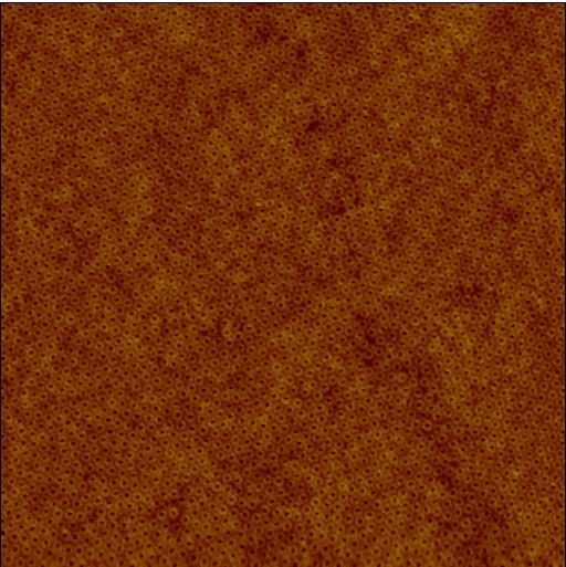


9 Figure S3 A B C D E F Figure S3. AFM images (3 μm x 3 μm, height mode) of reconstructed surface of S4VP(69k)/hPS(14k) with various mixing ratios: (A) neat, (B) 95/5, (C) 90/10, (D) 80/20, (E) 70/30, and (F) 60/40 (wt/wt), respectively.


10 B Figure S4 A B Ni C D
11 Figure S4. Thermal contact resistance estimation. (A) SEM image of SiN x pad/silicon ribbon junction of covalent bonding device. (B) SEM image of nickel bonded device. (C) Contact resistance (blue squares), defined by the total thermal resistance difference of two measured non-holey silicon ribbons, gradually increases toward lower temperature and peaks as 5K/μW at 50K. (D) Contact Resistance to total resistance ratio (black squares) of 55 nm pitched HS ribbon. Contact Resistance is around 3% at room temperature and decreases with lowering temperature, so it is neglected through the entire temperature range of our measurement. The scale bar is 1 µm for both (A) and (B).
12 Figure S5 Figure S5 Temperature dependent of thermal conductivity of multiple 55nm-pitch HS ribbons. The detailed ribbon dimension and the room temperature thermal conductivity are summarized in Table S1.
13 Table S1 Sample number Width (μm) Length (μm) 300K (W/m K) HS HS HS HS HS HS HS HS HS Table S1. Summery of room temperature thermal conductivity data shown in Figure S5. All 55nm pitch HS ribbons have low thermal conductivity, ranging from1.14 to 2.03 Wm -1 K -1, while no width dependence is observed. Note all data have been normalized by its porosity (φ~35%)
14 Figure S6 Figure S6 HS thermal conductivities at room temperature, compared with Hao et al s model (ref S5), Lee et al s model (ref S4), Hao et al s model corrected with our estimated correction factor, and Song and Chen experiment (ref S6). Thermoelectric transport direction of each data is perpendicular to the axial of the hole/pore in all cases. Array structure, porosity, and sample dimension are all marked for reference. All the present HS data are normalized by its porosity. Note: SA denotes for square array, HA denotes for hexagonal array.


15 Figure S7 A B C D
16 Figure S7. HS ribbon thermopower and electrical conductivity measurement (A) SEM image of a typical device used for electrical measurement. The left heating coil is used to create uniform temperature gradient. Two inner Pt electrodes are used for seebeck voltage measurement and temperature sensing, while all four electrdes are used for four probe ρ measurement. (B) SEM image of high magnification of HS ribbon for electrical measurement (C) Typical plot of seebeck volatage vs temperature difference. (D) I-V plot by four probe electrical resistance measurement. (C) and (D) plots are for the 55 nm pitch ribbon shown in Figure 3a.
Macroscopic Arrays of Block Copolymers with Areal Densities of 10 Terbit/inch 2 and Beyond
 Macroscopic Arrays of Block Copolymers with Areal Densities of 10 Terbit/inch 2 and Beyond Soojin Park*, Dong Hyun Lee, Bokyung Kim, Sung Woo Hong Department of Polymer Science and Engineering, University
Vertically aligned Ni magnetic nanowires fabricated by diblock-copolymer-directed Al thin film anodization
 Vertically aligned Ni magnetic nanowires fabricated by diblock-copolymer-directed Al thin film anodization Researcher: Kunbae (Kevin) Noh, Graduate Student, MAE Dept. and CMRR Collaborators: Leon Chen,
All fabrication was performed on Si wafers with 285 nm of thermally grown oxide to
 Supporting Information: Substrate preparation and SLG growth: All fabrication was performed on Si wafers with 285 nm of thermally grown oxide to aid in visual inspection of the graphene samples. Prior
Supplementary Information. for
 Electronic Supplementary Material (ESI) for ChemComm. This journal is The Royal Society of Chemistry 2014 Supplementary Information for Nanoslitting Phase-separated Block Copolymers by Solvent Swelling
Supporting Information: Model Based Design of a Microfluidic. Mixer Driven by Induced Charge Electroosmosis
 Supporting Information: Model Based Design of a Microfluidic Mixer Driven by Induced Charge Electroosmosis Cindy K. Harnett, Yehya M. Senousy, Katherine A. Dunphy-Guzman #, Jeremy Templeton * and Michael
A Functional Micro-Solid Oxide Fuel Cell with. Nanometer Freestanding Electrolyte
 Electronic Supplementary Material (ESI) for Journal of Materials Chemistry A. This journal is The Royal Society of Chemistry 2017 SUPPLEMENTARY INFORMATION A Functional Micro-Solid Oxide Fuel Cell with
Dr. Priyabrat Dash Office: BM-406, Mob: Webpage: MB: 205
 Email: dashp@nitrkl.ac.in Office: BM-406, Mob: 8895121141 Webpage: http://homepage.usask.ca/~prd822/ MB: 205 Nonmanufacturing In continuation from last class... 2 Top-Down methods Mechanical-energy methods
Supporting Information
 Supporting Information Fast-Response, Sensitivitive and Low-Powered Chemosensors by Fusing Nanostructured Porous Thin Film and IDEs-Microheater Chip Zhengfei Dai,, Lei Xu,#,, Guotao Duan *,, Tie Li *,,
Supporting information. In-situ TEM observation of phase transition of nanoscopic patterns on. baroplastic block copolymer film during nanoindentation
 Supporting information In-situ TEM observation of phase transition of nanoscopic patterns on baroplastic block copolymer film during nanoindentation Ara Jo, Gil Ho Gu, Hong Chul Moon, Sung Hyun Han, Sang
R Sensor resistance (Ω) ρ Specific resistivity of bulk Silicon (Ω cm) d Diameter of measuring point (cm)
 ρ Specific resistivity of bulk Silicon (Ω cm) d Diameter of measuring point (cm)") 4 Silicon Temperature Sensors 4.1 Introduction The KTY temperature sensor developed by Infineon Technologies is based on the principle of the Spreading Resistance. The expression Spreading Resistance derives
4 Silicon Temperature Sensors 4.1 Introduction The KTY temperature sensor developed by Infineon Technologies is based on the principle of the Spreading Resistance. The expression Spreading Resistance derives
SUPPLEMENTARY INFORMATIONS
 SUPPLEMENTARY INFORMATIONS Dynamic Evolution of Conducting Nanofilament in Resistive Switching Memories Jui-Yuan Chen, Cheng-Lun Hsin,,, Chun-Wei Huang, Chung-Hua Chiu, Yu-Ting Huang, Su-Jien Lin, Wen-Wei
Fe 2 O 3 on patterned fluorine doped tin oxide for efficient photoelectrochemical water splitting
 Electronic Supplementary Material (ESI) for Journal of Materials Chemistry A. This journal is The Royal Society of Chemistry 2015 Fe 2 O 3 on patterned fluorine doped tin oxide for efficient photoelectrochemical
Wireless implantable chip with integrated Nitinol-based pump for radio-controlled local drug delivery
 Electronic Supplementary Material (ESI) for Lab on a Chip. This journal is The Royal Society of Chemistry 2014 Electronic Supplementary Information Wireless implantable chip with integrated Nitinol-based
Supporting Information. graphene oxide films for detection of low. concentration biomarkers in plasma
 Supporting Information Wafer-scale high-resolution patterning of reduced graphene oxide films for detection of low concentration biomarkers in plasma Jinsik Kim a, Myung-Sic Chae a, Sung Min Lee b, Dahye
CHAPTER 9 AFM PROFILING AND NANOLITHOGRAPHY WITH NEEDLE-TIPPED CANTILEVERS
 CHAPTER 9 AFM PROFILING AND NANOLITHOGRAPHY WITH NEEDLE-TIPPED CANTILEVERS Since Ag 2 Ga nanoneedles can be directly grown on (or even in place of) the tips on AFM cantilevers using the pulling technique
Transfer Printing of Thermoreversible Ion Gels for Flexible Electronics
 Supporting Information Transfer Printing of Thermoreversible Ion Gels for Flexible Electronics Keun Hyung Lee, Sipei Zhang, Yuanyan Gu, Timothy P. Lodge * and C. Daniel Frisbie * Department of Chemical
Screen Printing of Highly Loaded Silver Inks on. Plastic Substrates Using Silicon Stencils
 Supporting Information Screen Printing of Highly Loaded Silver Inks on Plastic Substrates Using Silicon Stencils Woo Jin Hyun, Sooman Lim, Bok Yeop Ahn, Jennifer A. Lewis, C. Daniel Frisbie*, and Lorraine
Cost Effective 3D Glass Microfabrication for Advanced Packaging Applications
 Cost Effective 3D Glass Microfabrication for Advanced Packaging Applications Authors: Jeb. H Flemming, Kevin Dunn, James Gouker, Carrie Schmidt, Roger Cook ABSTRACT Historically, while glasses have many
High Aspect Ratio Silicon Wire Array Photoelectrochemical Cells
 S1 Supporting Information High Aspect Ratio Silicon Wire Array Photoelectrochemical Cells James R. Maiolo III, Brendan M. Kayes, Michael A. Filler, Morgan C. Putnam, Michael D. Kelzenberg, Harry A. Atwater*,
Mater. Res. Soc. Symp. Proc. Vol Materials Research Society
 Mater. Res. Soc. Symp. Proc. Vol. 940 2006 Materials Research Society 0940-P13-12 A Novel Fabrication Technique for Developing Metal Nanodroplet Arrays Christopher Edgar, Chad Johns, and M. Saif Islam
Platypus Gold Coated Substrates. Bringing Science to the Surface
 Platypus Gold Coated Substrates Bringing Science to the Surface Overview Gold Coated Substrates - Gold Coating Introduction - Glossary of Terms - Gold Coating Methods - Critical Features Platypus Gold
Fully-integrated, Bezel-less Transistor Arrays Using Reversibly Foldable Interconnects and Stretchable Origami Substrates
 Electronic Supplementary Material (ESI) for Nanoscale. This journal is The Royal Society of Chemistry 2016 Fully-integrated, Bezel-less Transistor Arrays Using Reversibly Foldable Interconnects and Stretchable
Microelectronic Device Instructional Laboratory. Table of Contents
 Introduction Process Overview Microelectronic Device Instructional Laboratory Introduction Description Flowchart MOSFET Development Process Description Process Steps Cleaning Solvent Cleaning Photo Lithography
Low-temperature, Simple and Fast Integration Technique of Microfluidic Chips by using a UV-curable Adhesive
 Low-temperature, Simple and Fast Integration Technique of Microfluidic Chips by using a UV-curable Adhesive Supplementary Information Channel fabrication Glass microchannels. A borosilicate glass wafer
UV15: For Fabrication of Polymer Optical Waveguides
 CASE STUDY UV15: For Fabrication of Polymer Optical Waveguides Master Bond Inc. 154 Hobart Street, Hackensack, NJ 07601 USA Phone +1.201.343.8983 Fax +1.201.343.2132 main@masterbond.com CASE STUDY UV15:
Supplementary Figure S1 Photograph of MoS 2 and WS 2 flakes exfoliated by different metal naphthalenide (metal = Na, K, Li), and dispersed in water.
, and dispersed in water.") Supplementary Figure S1 Photograph of MoS 2 and WS 2 flakes exfoliated by different metal naphthalenide (metal = Na, K, Li), and dispersed in water. Supplementary Figure S2 AFM measurement of typical LTMDs
Supplementary Figure S1 Photograph of MoS 2 and WS 2 flakes exfoliated by different metal naphthalenide (metal = Na, K, Li), and dispersed in water. Supplementary Figure S2 AFM measurement of typical LTMDs
Direct Patterning of Self Assembled Nano-Structures of Block Copolymers via Electron Beam Lithography
 Macromolecular Research, Vol. 13, No. 5, pp 435-440 (2005) Direct Patterning of Self Assembled Nano-Structures of Block Copolymers via Electron Beam Lithography Bo Kyung Yoon, Wonseok Hwang, Youn Jung
PROCESS FLOW AN INSIGHT INTO CMOS FABRICATION PROCESS
 Contents: VI Sem ECE 06EC63: Analog and Mixed Mode VLSI Design PROCESS FLOW AN INSIGHT INTO CMOS FABRICATION PROCESS 1. Introduction 2. CMOS Fabrication 3. Simplified View of Fabrication Process 3.1 Alternative
Lecture 22: Integrated circuit fabrication
 Lecture 22: Integrated circuit fabrication Contents 1 Introduction 1 2 Layering 4 3 Patterning 7 4 Doping 8 4.1 Thermal diffusion......................... 10 4.2 Ion implantation.........................
Single-digit-resolution nanopatterning with. extreme ultraviolet light for the 2.5 nm. technology node and beyond
 Electronic Supplementary Material (ESI) for Nanoscale. This journal is The Royal Society of Chemistry 205 Supplementary Information for: Single-digit-resolution nanopatterning with extreme ultraviolet
Graphene Biotransistor Interfaced with a Nitrifying Biofilm
 Supporting Information Graphene Biotransistor Interfaced with a Nitrifying Biofilm Morgan Brown 1, Leila Barker 2, Lewis Semprini 2 and Ethan D. Minot 1 1 Department of Physics, Oregon State University
In operandi observation of dynamic annealing: a case. Supplementary Material
 In operandi observation of dynamic annealing: a case study of boron in germanium nanowire devices Supplementary Material Maria M. Koleśnik-Gray, 1,3,4 Christian Sorger, 1 Subhajit Biswas, 2,3 Justin D.
Supporting Online Material for
 www.sciencemag.org/cgi/content/full/321/5891/936/dc1 Supporting Online Material for Density Multiplication and Improved Lithography by Directed Block Copolymer Assembly Ricardo Ruiz,* Huiman Kang, François
A discussion of crystal growth, lithography, etching, doping, and device structures is presented in
 Chapter 5 PROCESSING OF DEVICES A discussion of crystal growth, lithography, etching, doping, and device structures is presented in the following overview gures. SEMICONDUCTOR DEVICE PROCESSING: AN OVERVIEW
Supporting Information for
 Electronic Supplementary Material (ESI) for Nanoscale. This journal is The Royal Society of Chemistry 2015 Supporting Information for Large-Scale Freestanding Nanometer-thick Graphite Pellicle for Mass
6.777J/2.732J Design and Fabrication of Microelectromechanical Devices Spring Term Solution to Problem Set 2 (16 pts)
") 6.777J/2.732J Design and Fabrication of Microelectromechanical Devices Spring Term 2007 By Brian Taff (Adapted from work by Feras Eid) Solution to Problem Set 2 (16 pts) Issued: Lecture 4 Due: Lecture
6.777J/2.732J Design and Fabrication of Microelectromechanical Devices Spring Term 2007 By Brian Taff (Adapted from work by Feras Eid) Solution to Problem Set 2 (16 pts) Issued: Lecture 4 Due: Lecture
Czochralski Crystal Growth
 Czochralski Crystal Growth Crystal Pulling Crystal Ingots Shaping and Polishing 300 mm wafer 1 2 Advantage of larger diameter wafers Wafer area larger Chip area larger 3 4 Large-Diameter Wafer Handling
Metallization deposition and etching. Material mainly taken from Campbell, UCCS
 Metallization deposition and etching Material mainly taken from Campbell, UCCS Application Metallization is back-end processing Metals used are aluminum and copper Mainly involves deposition and etching,
ECE 440 Lecture 27 : Equilibrium P-N Junctions I Class Outline:
 ECE 440 Lecture 27 : Equilibrium P-N Junctions I Class Outline: Fabrication of p-n junctions Contact Potential Things you should know when you leave Key Questions What are the necessary steps to fabricate
There are basically two approaches for bulk micromachining of. silicon, wet and dry. Wet bulk micromachining is usually carried out
 57 Chapter 3 Fabrication of Accelerometer 3.1 Introduction There are basically two approaches for bulk micromachining of silicon, wet and dry. Wet bulk micromachining is usually carried out using anisotropic
Total Points = 110 possible (graded out of 100)
") Lab Report 1 Table of Contents 1. Profiles & Layout (9 Points) 2. Process Procedures (20 points) 3. Calculations (36 Points) 4. Questions (35 Points) 5. Bonus Questions (10 Points) Total Points = 110 possible
Lab Report 1 Table of Contents 1. Profiles & Layout (9 Points) 2. Process Procedures (20 points) 3. Calculations (36 Points) 4. Questions (35 Points) 5. Bonus Questions (10 Points) Total Points = 110 possible
Fabrication of sub-100nm thick Nanoporous silica thin films
 Fabrication of sub-100nm thick Nanoporous silica thin films Abstract M. Ojha, W. Cho, J. L. Plawsky, W. N. Gill Department of chemical and biological engineering, Rensselaer Polytechnic Institute Low refractive
TED PELLA, INC. Microscopy Products for Science and Industry
 PELCO SILICON NITRIDE, SILICON DIOXIDE, BLANK SILICON SUBSTRATES & APERTURES FOR TEM Clean, Debris-free with Exact 3mm TEM Frame and EasyGrip Edges PELCO Silicon Nitride Support Films for TEM Hydrophilic
Supporting Information for the Manuscript: Dramatic. Increase In Polymer Glass Transition Temperature. Under Extreme Nanoconfinement In
 Supporting Information for the Manuscript: Dramatic Increase In Polymer Glass Transition Temperature Under Extreme Nanoconfinement In Weakly-Interacting Nanoparticle Films Haonan Wang, Jyo Lyn Hor, Yue
Macrophase Separation Using Block Copolymer Blends
 Macrophase Separation Using Block Copolymer Blends Rachel Philiph 1,2, Kameron Oser 1, Sam Nicaise 1, and Karl Berggren 1 1 Department of Electrical Engineering and Computer Science, Massachusetts Institute
Intlvac Nanochrome I Sputter System (intlvac_sputter)
") 1. Intlvac_Sputter Specifications The Intlvac Nanochrome I sputter system is configured for DC, AC (40 khz), and RF (13.56 MHz) magnetron sputtering. They system has in-situ quartz lamp heating up to 200C,
1. Intlvac_Sputter Specifications The Intlvac Nanochrome I sputter system is configured for DC, AC (40 khz), and RF (13.56 MHz) magnetron sputtering. They system has in-situ quartz lamp heating up to 200C,
A High Speed Surface Illuminated Si Photodiode. Using Microstructured Holes for Absorption. Enhancements at nm wavelength
 A High Speed Surface Illuminated Si Photodiode Using Microstructured Holes for Absorption Enhancements at 900 1000 nm wavelength Supporting Information Yang Gao, Hilal Cansizoglu, Soroush Ghandiparsi,
Micro-Nano Fabrication Research
 Micro-Nano Fabrication Research Technical Education Quality Improvement Programme 22-23 December 2014 Dr. Rakesh G. Mote Assistant Professor Department of Mechanical Engineering IIT Bombay rakesh.mote@iitb.ac.in;
IC/MEMS Fabrication - Outline. Fabrication
 IC/MEMS Fabrication - Outline Fabrication overview Materials Wafer fabrication The Cycle: Deposition Lithography Etching Fabrication IC Fabrication Deposition Spin Casting PVD physical vapor deposition
Chapter 2 Manufacturing Process
 Digital Integrated Circuits A Design Perspective Chapter 2 Manufacturing Process 1 CMOS Process 2 CMOS Process (n-well) Both NMOS and PMOS must be built in the same silicon material. PMOS in n-well NMOS
NanoSystemsEngineering: NanoNose Final Status, March 2011
 1 NanoSystemsEngineering: NanoNose Final Status, March 2011 The Nanonose project is based on four research projects (VCSELs, 3D nanolithography, coatings and system integration). Below, the major achievements
Lecture 5. SOI Micromachining. SOI MUMPs. SOI Micromachining. Silicon-on-Insulator Microstructures. Agenda:
 EEL6935 Advanced MEMS (Spring 2005) Instructor: Dr. Huikai Xie SOI Micromachining Agenda: SOI Micromachining SOI MUMPs Multi-level structures Lecture 5 Silicon-on-Insulator Microstructures Single-crystal
Electronic Supplementary Information
 Electronic Supplementary Material (ESI) for Journal of Materials Chemistry C. This journal is The Royal Society of Chemistry 2015 Electronic Supplementary Information Water stability and orthogonal patterning
PHYS 534 (Fall 2008) Process Integration OUTLINE. Examples of PROCESS FLOW SEQUENCES. >Surface-Micromachined Beam
 Process Integration OUTLINE. Examples of PROCESS FLOW SEQUENCES. >Surface-Micromachined Beam") PHYS 534 (Fall 2008) Process Integration Srikar Vengallatore, McGill University 1 OUTLINE Examples of PROCESS FLOW SEQUENCES >Semiconductor diode >Surface-Micromachined Beam Critical Issues in Process
PHYS 534 (Fall 2008) Process Integration Srikar Vengallatore, McGill University 1 OUTLINE Examples of PROCESS FLOW SEQUENCES >Semiconductor diode >Surface-Micromachined Beam Critical Issues in Process
Chapter 2 Anti-Dot Substrates
 19 Chapter 2 Anti-Dot Substrates 2.1 Polymer Sphere Lithography Background and Summary Polymer sphere lithography and, in particular, nanosphere lithography have gained recent attention for a wide range
Large-scale fabrication of free-standing and sub-μm PDMS through-holes membranes
 Electronic Supplementary Material (ESI) for. This journal is The Royal Society of Chemistry 2018 Large-scale fabrication of free-standing and sub-μm PDMS through-holes membranes Hai Le-The,* a Martijn
Supporting Information for
 Supporting Information for Core-Shell CdS-Cu 2 S Nanorod Array Solar Cells Andrew Barnabas Wong,, Sarah Brittman,, Yi Yu,, Neil P. Dasgupta,, and Peidong Yang,,,,* Department of Chemistry, University of
Supplementary Figure 1 The lithium polysulfide distribution on the patterned electrode.
 Supplementary Figure 1.The lithium polysulfide distribution on the patterned electrode. SEM image of the ITO-carbon electrode after dipping into Li 2 S 8 solution and drying, which shows the random distribution
Micro-Electro-Mechanical Systems (MEMS) Fabrication. Special Process Modules for MEMS. Principle of Sensing and Actuation
 Fabrication. Special Process Modules for MEMS. Principle of Sensing and Actuation") Micro-Electro-Mechanical Systems (MEMS) Fabrication Fabrication Considerations Stress-Strain, Thin-film Stress, Stiction Special Process Modules for MEMS Bonding, Cavity Sealing, Deep RIE, Spatial forming
Micro-Electro-Mechanical Systems (MEMS) Fabrication Fabrication Considerations Stress-Strain, Thin-film Stress, Stiction Special Process Modules for MEMS Bonding, Cavity Sealing, Deep RIE, Spatial forming
Ultrasensitive and Highly Stable Resistive Pressure Sensors with. Biomaterial-Incorporated Interfacial Layers for Wearable
 Supporting Information Ultrasensitive and Highly Stable Resistive Pressure Sensors with Biomaterial-Incorporated Interfacial Layers for Wearable Health-Monitoring and Human-Machine Interfaces Hochan Chang,,
MICROFLUIDIC ASSEMBLY BLOCKS
 ELECTRONIC SUPPLEMENTARY INFORMATION MICROFLUIDIC ASSEMBLY BLOCKS Minsoung Rhee 1,2 and Mark A. Burns 1,3, * 1 Department of Chemical Engineering, the University of Michigan 2300 Hayward St. 3074 H.H.
Effective Post-TSV-DRIE Wet Clean Process for Through Silicon Via Applications
 Effective Post-TSV-DRIE Wet Clean Process for Through Silicon Via Applications Laura Mauer, John Taddei, John Clark, Kenji Nulman Veeco Precision Surface Processing Horsham, PA 19044 lmauer@veeco.com Abstract
Ajay Kumar Gautam [VLSI TECHNOLOGY] VLSI Technology for 3RD Year ECE/EEE Uttarakhand Technical University
![Ajay Kumar Gautam [VLSI TECHNOLOGY] VLSI Technology for 3RD Year ECE/EEE Uttarakhand Technical University](/thumbs/75/72824557.jpg "Ajay Kumar Gautam [VLSI TECHNOLOGY] VLSI Technology for 3RD Year ECE/EEE Uttarakhand Technical University") 2014 Ajay Kumar Gautam [VLSI TECHNOLOGY] VLSI Technology for 3RD Year ECE/EEE Uttarakhand Technical University Page1 Syllabus UNIT 1 Introduction to VLSI Technology: Classification of ICs, Scale of integration,
2014 Ajay Kumar Gautam [VLSI TECHNOLOGY] VLSI Technology for 3RD Year ECE/EEE Uttarakhand Technical University Page1 Syllabus UNIT 1 Introduction to VLSI Technology: Classification of ICs, Scale of integration,
Supplementary Information for
 Supplementary Information for An ultra-sensitive resistive pressure sensor based on hollow-sphere microstructure induced elasticity in conducting polymer film Lijia Pan, 1,2 Alex Chortos, 3 Guihua Yu,
Procedia Chemistry 1 (2009) Proceedings of the Eurosensors XXIII conference
 Proceedings of the Eurosensors XXIII conference") Procedia Chemistry 1 (2009) 609 613 Procedia Chemistry www.elsevier.com/locate/procedia Proceedings of the Eurosensors XXIII conference Thermal Characterization of Polycrystalline CVD Diamond Thin Films
Procedia Chemistry 1 (2009) 609 613 Procedia Chemistry www.elsevier.com/locate/procedia Proceedings of the Eurosensors XXIII conference Thermal Characterization of Polycrystalline CVD Diamond Thin Films
PARAMETER EFFECTS FOR THE GROWTH OF THIN POROUS ANODIC ALUMINUM OXIDES
 10.1149/1.2794473, The Electrochemical Society PARAMETER EFFECTS FOR THE GROWTH OF THIN POROUS ANODIC ALUMINUM OXIDES S. Yim a, C. Bonhôte b, J. Lille b, and T. Wu b a Dept. of Chem. and Mat. Engr., San
Electronic Supplementary Information. Etching-free patterning method for electrical characterizations of atomically thin CVD-grown MoSe 2 film
 Electronic Supplementary Material (ESI) for Nanoscale. This journal is The Royal Society of Chemistry 2014 Electronic Supplementary Information Etching-free patterning method for electrical characterizations
Fabrication of Nanoscale Silicon Membranes on SOI Wafers Using Photolithography and Selective Etching Techniques:
 Fabrication of Nanoscale Silicon Membranes on SOI Wafers Using Photolithography and Selective Etching Techniques: Participant Names: Moriah Faint, Marcos Rodriguez Mentor: Frank Tsang Date: 1 Introduction
using Stencil Masks Oscar Vazquez-Mena, Takumi Sannomiya, Mahmut Tosun, Veronica Savu, Luis G. Villanueva, Janos Voros, Juergen Brugger
 High Resolution Resistless Nanopatterning on Polymer and Flexible Substrates for Plasmonic Biosensing using Stencil Masks Oscar Vazquez-Mena, Takumi Sannomiya, Mahmut Tosun, Veronica Savu, Luis G. Villanueva,
Change in stoichiometry
 Measurement of Gas Sensor Performance Gas sensing materials: 1. Sputtered ZnO film (150 nm (Massachusetts Institute of Technology) 2. Sputtered SnO 2 film (60 nm) (Fraunhofer Institute of Physical Measurement
EE 5344 Introduction to MEMS. CHAPTER 3 Conventional Si Processing
 3. Conventional licon Processing Micromachining, Microfabrication. EE 5344 Introduction to MEMS CHAPTER 3 Conventional Processing Why silicon? Abundant, cheap, easy to process. licon planar Integrated
350 C for 8 hours in argon atmosphere. Supplementary Figures. Supplementary Figure 1 High-temperature annealing of BP flakes on SiO 2.
 Supplementary Figures Supplementary Figure 1 High-temperature annealing of BP flakes on SiO 2. (a-d) The optical images of three BP flakes on a SiO 2 substrate before (a,b) and after annealing (c,d) at
Process Flow in Cross Sections
 Process Flow in Cross Sections Process (simplified) 0. Clean wafer in nasty acids (HF, HNO 3, H 2 SO 4,...) --> wear gloves! 1. Grow 500 nm of SiO 2 (by putting the wafer in a furnace with O 2 2. Coat
Aligned Carbon Nanofibre-Polymer Composite Membranes. CNT Growth and Manipulation. Eleanor Campbell Dept. of Physics, Göteborg University
 Aligned Carbon Nanofibre-Polymer Composite Membranes CNT Growth and Manipulation Eleanor Campbell Dept. of Physics, Göteborg University Plasma CVD Growth Polymer/Nanofibre Composite Low ambient temperature
Fabrication Process. Crystal Growth Doping Deposition Patterning Lithography Oxidation Ion Implementation CONCORDIA VLSI DESIGN LAB
 Fabrication Process Crystal Growth Doping Deposition Patterning Lithography Oxidation Ion Implementation 1 Fabrication- CMOS Process Starting Material Preparation 1. Produce Metallurgical Grade Silicon
In situ TEM Characterization of Shear Stress-Induced Interlayer. Sliding in the Cross Section View of Molybdenum Disulfide
 In situ TEM Characterization of Shear Stress-Induced Interlayer Sliding in the Cross Section View of Molybdenum Disulfide Juan Pablo Oviedo, Santosh KC, Ning Lu, Jinguo Wang, Kyeongjae Cho, Robert M. Wallace,
In-situ Synthesis of Carbon Nanotube-Graphite. Electronic Devices and Their Integrations onto. Surfaces of Live Insects and Plants
 Supporting Information In-situ Synthesis of Carbon Nanotube-Graphite Electronic Devices and Their Integrations onto Surfaces of Live Insects and Plants Kyongsoo Lee,, Jihun Park,, Mi-Sun Lee,, Joohee Kim,,
WP7 JRA2 JRA2 Research on High Precision Manufacturing. Investigation of optimum NIL stamp fabrication method to copy sub-10 nm BCP features
 DELIVERABLE REPORT WP7 JRA2 JRA2 Research on High Precision Manufacturing D7.1 Investigation of optimum NIL stamp fabrication method to copy sub-10 nm BCP features M18 NFFA-Europe has received funding
Today s Class. Materials for MEMS
 Lecture 2: VLSI-based Fabrication for MEMS: Fundamentals Prasanna S. Gandhi Assistant Professor, Department of Mechanical Engineering, Indian Institute of Technology, Bombay, Recap: Last Class What is
SUPPLEMENTAL INFORMATION: 1. Supplemental methods 2. Supplemental figure legends 3. Supplemental figures
 Supplementary Material (ESI) for Lab on a Chip This journal is The Royal Society of Chemistry 2008 A microfluidics-based turning assay reveals complex growth cone responses to integrated gradients of substrate-bound
Lithography Independent Fabrication of Nano-MOS-Transistors with W = 25 nm and L = 25 nm
 Lithography Independent Fabrication of Nano-MOS-Transistors with W = 25 nm and L = 25 nm J. T. Horstmann John_Horstmann@ieee.org C. Horst Christian.Horst@udo.edu K. F. Goser goser@ieee.org Abstract The
Compact hybrid plasmonic-si waveguide structures utilizing Albanova E-beam lithography system
 Compact hybrid plasmonic-si waveguide structures utilizing Albanova E-beam lithography system Introduction Xu Sun Laboratory of Photonics and Microwave Engineering, Royal Institute of Technology (KTH),
Supplementary Materials for
 www.sciencemag.org/cgi/content/full/336/6084/1007/dc1 Supplementary Materials for Unidirectional Growth of Microbumps on (111)-Oriented and Nanotwinned Copper Hsiang-Yao Hsiao, Chien-Min Liu, Han-wen Lin,
EE C245 ME C218 Introduction to MEMS Design Fall 2011
 Lecture Outline EE C245 ME C218 Introduction to MEMS Design Fall 2011 Prof. Clark T.-C. Nguyen Dept. of Electrical Engineering & Computer Sciences University of California at Berkeley Berkeley, CA 94720
Chapter 2 MOS Fabrication Technology
 Chapter 2 MOS Fabrication Technology Abstract This chapter is concerned with the fabrication of metal oxide semiconductor (MOS) technology. Various processes such as wafer fabrication, oxidation, mask
Correlating the scattered intensities of P3HT and PCBM to the current. densities of polymer solar cells
 Supplementary Information for Correlating the scattered intensities of P3HT and PCBM to the current densities of polymer solar cells Enrique D. Gomez*, Katherine P. Barteau, He Wang, Michael F. Toney,
9/4/2008 GMU, ECE 680 Physical VLSI Design
 ECE680: Physical VLSI Design Chapter II CMOS Manufacturing Process 1 Dual-Well Trench-Isolated CMOS Process gate-oxide TiSi 2 AlCu Tungsten SiO 2 p-well poly n-well SiO 2 n+ p-epi p+ p+ 2 Schematic Layout
Fabrication of regular silicon microstructures by photo-electrochemical etching of silicon
 phys. stat. sol. (c) 2, No. 9, 3198 3202 (2005) / DOI 10.1002/pssc.200461110 Fabrication of regular silicon microstructures by photo-electrochemical etching of silicon G. Barillaro *, P. Bruschi, A. Diligenti,
Colossal Electroresistance in. (La 1-y Pr y ) 0.67 Ca 0.33 MnO 3. Rafiya Javed. July 29, Abstract
 0.67 Ca 0.33 MnO 3. Rafiya Javed. July 29, Abstract") Colossal Electroresistance in (La 1-y Pr y ) 0.67 Ca 0.33 MnO 3 Rafiya Javed July 29, 2010 Abstract At low temperatures, LaPrCaMnO3(LPCMO), a perovskite manganite, exhibits a coexistence of ferromagnetic
Colossal Electroresistance in (La 1-y Pr y ) 0.67 Ca 0.33 MnO 3 Rafiya Javed July 29, 2010 Abstract At low temperatures, LaPrCaMnO3(LPCMO), a perovskite manganite, exhibits a coexistence of ferromagnetic
Surface micromachining and Process flow part 1
 Surface micromachining and Process flow part 1 Identify the basic steps of a generic surface micromachining process Identify the critical requirements needed to create a MEMS using surface micromachining
Microfabrication of Heterogeneous, Optimized Compliant Mechanisms SUNFEST 2001 Luo Chen Advisor: Professor G.K. Ananthasuresh
 Microfabrication of Heterogeneous, Optimized Compliant Mechanisms SUNFEST 2001 Luo Chen Advisor: Professor G.K. Ananthasuresh Fig. 1. Single-material Heatuator with selective doping on one arm (G.K. Ananthasuresh)
SUPPLEMENTARY INFORMATION
 Supplementary Figures SUPPLEMENTARY INFORMATION Supplementary Figure S1. Schematic Representation of temperature-controlled sonication apparatus. 1 Solution Abs (a.u.) 0.18 HiPco SWNT Dispersion in rr-p3ddt/toluene
Hierarchical and Well-ordered Porous Copper for Liquid Transport Properties Control
 Supporting Information Hierarchical and Well-ordered Porous Copper for Liquid Transport Properties Control Quang N. Pham 1, Bowen Shao 2, Yongsung Kim 3 and Yoonjin Won 1,2 * 1 Department of Mechanical
Introduction to Micro/Nano Fabrication Techniques. Date: 2015/05/22 Dr. Yi-Chung Tung. Fabrication of Nanomaterials
 Introduction to Micro/Nano Fabrication Techniques Date: 2015/05/22 Dr. Yi-Chung Tung Fabrication of Nanomaterials Top-Down Approach Begin with bulk materials that are reduced into nanoscale materials Ex:
Atomic Structure of Ultrathin Gold Nanowires
 Supporting Information For Atomic Structure of Ultrathin Gold Nanowires Yi Yu, 1,2 Fan Cui, 1,2 Jianwei Sun, 1,2 and Peidong Yang* 1,2,3,4 1 Department of Chemistry, University of California, Berkeley,
Chapter 4 Fabrication Process of Silicon Carrier and. Gold-Gold Thermocompression Bonding
 Chapter 4 Fabrication Process of Silicon Carrier and Gold-Gold Thermocompression Bonding 4.1 Introduction As mentioned in chapter 2, the MEMs carrier is designed to integrate the micro-machined inductor
Proceedings Post Fabrication Processing of Foundry MEMS Structures Exhibiting Large, Out-of-Plane Deflections
 Proceedings Post Fabrication Processing of Foundry MEMS Structures Exhibiting Large, Out-of-Plane Deflections LaVern Starman 1, *, John Walton 1, Harris Hall 1 and Robert Lake 2 1 Sensors Directorate,
Chemical Vapor Deposition
 Chemical Vapor Deposition ESS4810 Lecture Fall 2010 Introduction Chemical vapor deposition (CVD) forms thin films on the surface of a substrate by thermal decomposition and/or reaction of gas compounds
Ultrasonic Micromachining in the fabrication of MEMS Micro-sensors
 Ultrasonic Micromachining in the fabrication of MEMS Micro-sensors Jamil Akhtar Professor AcSIR New Delhi Chief Scientist & Head, CSIR-CEERI, Pilani, INDIA CEERI, Pilani A constituent laboratory of CSIR,
A Deep Silicon RIE Primer Bosch Etching of Deep Structures in Silicon
 A Deep Silicon RIE Primer Bosch Etching of Deep Structures in Silicon April 2009 A Deep Silicon RIE Primer 1.0) Etching: Silicon does not naturally etch anisotropically in fluorine based chemistries. Si