IBMF STATE OF GOOD REPAIR UPGRADES
|
|
|
- Joanna O’Brien’
- 6 years ago
- Views:
Transcription

1 IBMF STATE OF GOOD REPAIR UPGRADES City of North Las Vegas, Nevada SPECIFICATIONS For December 26, 2013
2 TABLE OF CONTENTS SECTION SECTION SECTION SECTION SECTION SECTION SECTION SECTION SECTION SECTION SECTION SECTION SECTION SECTION SECTION SECTION SECTION SECTION SECTION SECTION SECTION SECTION SECTION SECTION SECTION SECTION SECTION SECTION SECTION SECTION SECTION SECTION RTC IBMF SOGR SUMMARY CONTRACT MODIFICATION PROCEDURES PAYMENT PROCEDURES PROJECT MANAGEMENT AND COORDINATION PHOTOGRAPHIC DOCUMENTATION PRODUCT REQUIREMENTS CLOSEOUT PROCEDURES PROJECT RECORD DOCUMENTS OPERATION AND MAINTENANCE DATA DEMONSTRATION AND TRAINING SOILS AGGREGATE EXCAVATION AND FILL BACKFILL TRENCHING AGGREGATE BASE COURSE PAVING PAVEMENT MARKING CAST-IN-PLACE CONCRETE STRUCTURAL STEEL FRAMING METAL FABRICATIONS POLYVINYL CHLORIDE (PVC) MEMBRANE ROOFING DOORS FINISH HARDWARE GYPSUM BOARD EXTERIOR PAINTING INTERIOR PAINTING HIGH-PERFORMANCE COATINGS PREFABRICATED METAL SECURITY BOOTH PANTOGRAPH LIFT MOTORS AND CONTROLLERS HANGERS AND SUPPORTS i TABLE OF CONTENTS
3 TABLE OF CONTENTS (CONTINUED) SECTION SECTION SECTION SECTION SECTION SECTION SECTION SECTION SECTION SECTION SECTION SECTION SECTION SECTION SECTION SECTION SECTION SECTION SECTION SECTION SECTION VIBRATION ISOLATION MECHANICAL IDENTIFICATION TESTING, ADJUSTING, AND BALANCING COMMISSIONING OF HVAC DIRECT EVAPORATIVE COOLING SECTION PACKAGED ROOFTOP AIR CONDITIONING UNITS SPLIT-SYSTEM AIR-CONDITIONERS IDENTIFICATION FOR ELECTRICAL SYSTEMS PHOTOVOLTAIC SYSTEM INTEGRATED MOUNTING SYSTEM CABINETS, ENCLOSURES AND RACKS COMMUNICATIONS BACKBONE CABLING COMMUNICATIONS HORIZONTAL CABLING ELECTRONIC SYSTEMS GENERAL REQUIREMENTS CONDUCTORS AND CABLES FIBER OPTICS SYSTEM SIGNAL GROUNDING RACEWAYS AND BOXES ACCESS CONTROL SYSTEM ELECTRONIC SYSTEMS AND COMPONENTS DURESS ALARM SYSTEM VIDEO SURVELILLANCE (CCTV) SYSTEM RTC IBMF SOGR ii TABLE OF CONTENTS
4 SECTION SUMMARY PART 1 - GENERAL 1.1 RELATED DOCUMENTS A. Drawings and general provisions of the Contract, including General and Supplementary Conditions and other Division 1 Specification Sections, apply to this Section. 1.2 SUMMARY A. This Section includes the following: 1. Work covered by the Contract Documents. 2. Type of the Contract. 3. Work phases. 4. Use of premises. 5. Owner s Occupancy Requirements. 6. Work restrictions. 7. Specification formats and conventions. 1.3 WORK COVERED BY CONTRACT DOCUMENTS A. Project Identification: Security Upgrades at the Integrated Bus Maintenance Facility, City of North Las Vegas NV. B. Owner: The Regional Transportation Commission, 600 S. Grand Central Parkway, Suite 350, C. Engineer; URS 811 Grier Drive, D. Resident Engineer: Regional Transportation Commission, 600 S. Grand Central Parkway, Las Vegas NV E. This work shall consist of but not be limited to the following: 1. On-site and Building Improvements, including: excavation, trenching, utilities protection, concrete paving, paving, piping and conduits, sidewalk protection, landscaping, security equipment, HVAC work, door repair work, trench plating/protection, pull strings, hangers/supports and security devices. 2. The work shall be coordinated in and around the Bus Schedules and Operations as well as the Building systems and operations and shall not negatively impact the overall operations of the site. RTC IBMF SOGR /07/2013 SUMMARY
5 1.4 WORK PHASES The work for this Contract shall be phased as necessary to coordinate with Bus Schedules and Operations. 1.5 USE OF PREMISES A. General: Contractor shall coordinate with the Owner and Bus Operator to identify a suitable area as required for the storage of materials, staging area. Contractor s use of existing premises is limited by the operations of vehicles, passenger service and transfers and shall be clearly defined based on the Contractor s proposed work sequence. 1.6 WORK SEQUENCE A. Before commencing Work, submit a schedule showing the sequence, commencement dates and completion dates for the Owner s review and approval. 1.7 WORK RESTRICTIONS A. General: Contractor shall coordinate with the Owner and Bus Operator to identify a suitable area as required for the storage of materials, staging area. Contractor s use of existing premises is limited by the operations of vehicles, passenger service and transfers and shall be clearly defined based on the Contractor s proposed work sequence. PART 2 - PRODUCTS (Not used) PART 3 - EXECUTION (Not used) END OF SECTION RTC IBMF SOGR /07/2013 SUMMARY
6 SECTION CONTRACT MODIFICATION PROCEDURES PART 1 - GENERAL 1.1 RELATED DOCUMENTS A. Drawings and general provisions of the Contract, including General and Supplementary Conditions and other Division 1 Specification Sections, apply to this Section. 1.2 SUMMARY A. This Section specifies administrative and procedural requirements for handling and processing Contract modifications. B. Related Sections include the following: 1. Division 1 Section "Product Requirements" for administrative procedures for handling requests for substitutions made after Contract award. 1.3 MINOR CHANGES IN THE WORK A. The Regional Transportation Commission of Southern Nevada (RTC) will issue supplemental instructions authorizing Minor Changes in the Work, not involving adjustment to the Contract Sum or the Contract Time, on a form designated by Resident Engineer. 1.4 PROPOSAL REQUESTS A. Owner-Initiated Proposal Requests: will issue a detailed description of proposed changes in the Work that may require adjustment to the Contract Sum or the Contract Time. If necessary, the description will include supplemental or revised Drawings and Specifications. 1. Proposal Requests issued by the Resident Engineer are for information only. Do not consider them instructions either to stop work in progress or to execute the proposed change. 2. Within time specified in Proposal Request after receipt of Proposal Request, submit a quotation estimating cost adjustments to the Contract Sum and the Contract Time necessary to execute the change. a. Include a list of quantities of products required or eliminated and unit costs, with total amount of purchases and credits to be made. If requested, furnish survey data to substantiate quantities. RTC IBMF SOGR /07/2013 CONTRACT MODIFICATION PROCEDURES
7 b. Indicate applicable taxes, delivery charges, equipment rental, and amounts of trade discounts. c. Include costs of labor and supervision directly attributable to the change. d. Include an updated Contractor's Construction Schedule that indicates the effect of the change, including, but not limited to, changes in activity duration, start and finish times, and activity relationship. Use available total float before requesting an extension of the Contract Time. B. Contractor-Initiated Proposals: If latent or unforeseen conditions require modifications to the Contract, Contractor may propose changes by submitting a request for a change to Resident Engineer. If necessary, the description will include supplemental or revised drawings or specifications. 1. Include a statement outlining reasons for the change and the effect of the change on the Work. Provide a complete description of the proposed change. Indicate the effect of the proposed change on the Contract Sum and the Contract Time. 2. Include a list of quantities of products required or eliminated and unit costs, with total amount of purchases and credits to be made. If requested, furnish survey data to substantiate quantities. 3. Indicate applicable taxes, delivery charges, equipment rental, and amounts of trade discounts. 4. Include costs of labor and supervision directly attributable to the change. 5. Include an updated Contractor's Construction Schedule that indicates the effect of the change, including, but not limited to, changes in activity duration, start and finish times, and activity relationship. Use available total float before requesting an extension of the Contract Time. 6. Comply with requirements in Division 1 Section "Product Requirements" if the proposed change requires substitution of one product or system for product or system specified. C. Proposal Request Form: Use form included designated by Resident Engineer. 1.5 CHANGE ORDER PROCEDURES A. On Owner's approval of a Proposal Request, the Resident Engineer will issue a Change Order for signatures of Owner and Contractor on form included per GC CONSTRUCTION CHANGE DIRECTIVE A. Construction Change Directive: the Resident Engineer may issue a Construction Change Directive. Construction Change Directive instructs Contractor to proceed with a change in the Work, for subsequent inclusion in a Change Order. 1. Construction Change Directive contains a complete description of change in the Work. It also designates method to be followed to determine change in the Contract Sum or the Contract Time. B. Documentation: Maintain detailed records on a time and material basis of work required by the Construction Change Directive. RTC IBMF SOGR /07/2013 CONTRACT MODIFICATION PROCEDURES
8 1. After completion of change, submit an itemized account and supporting data necessary to substantiate cost and time adjustments to the Contract. PART 2 - PRODUCTS (Not Used) PART 3 - EXECUTION (Not Used) END OF SECTION RTC IBMF SOGR /07/2013 CONTRACT MODIFICATION PROCEDURES
9 SECTION PAYMENT PROCEDURES PART 1 - GENERAL 1.1 RELATED DOCUMENTS A. Drawings and general provisions of the Contract, including General and Supplementary Conditions and other Division 1 Specification Sections, apply to this Section. 1.2 SUMMARY A. This Section specifies administrative and procedural requirements necessary to prepare and process Applications for Payment. B. Related Sections include the following: 1. Division 1 Section "Contract Modification Procedures" for administrative procedures for handling changes to the Contract. 2. Division 1 Section "Construction Progress Documentation" for administrative requirements governing preparation and submittal of Contractor's Construction Schedule and Submittals Schedule. 1.3 DEFINITIONS A. Schedule of Values: A statement furnished by Contractor allocating portions of the Contract Sum to various portions of the Work and used as the basis for reviewing Contractor's Applications for Payment. 1.4 SCHEDULE OF VALUES A. Coordination: Coordinate preparation of the Schedule of Values with preparation of Contractor's Construction Schedule. The Schedule shall be in a format approved by the Resident Engineer. 1. Correlate line items in the Schedule of Values with other required administrative forms and schedules, including the following: a. Application for Payment forms with Continuation Sheets. b. Submittals Schedule. c. Contractor's Construction Schedule. 2. Submit the Schedule of Values to Resident Engineer no more than 15 days after Notice to Proceed. RTC IBMF SOGR /07/2013 PAYMENT PROCEDURES
10 B. Format and Content: Use the Project Manual table of contents as a guide to establish line items for the Schedule of Values. Provide at least one line item for each Specification Section. 1. Identification: Include the following Project identification on the Schedule of Values: a. Project name/number and location. b. Contractor's name and address. c. Date of submittal. 2. Arrange the Schedule of Values in tabular form with separate columns to indicate the following for each item listed: a. Related Specification Section or Division. b. Description of the Work. c. Name of subcontractor. d. Name of manufacturer or fabricator. e. Name of supplier. f. Change Orders (numbers) that affect value. g. Dollar value. 1) Percentage of the Contract Sum to nearest one-hundredth percent, adjusted to total 100 percent. 3. Provide a breakdown of the Contract Sum in enough detail to facilitate continued evaluation of Applications for Payment and progress reports. Coordinate with the Project Manual table of contents. Provide several line items for principal subcontract amounts, where appropriate. 4. Round amounts to nearest whole dollar; total shall equal the Contract Sum. 5. Provide a separate line item in the Schedule of Values for each part of the Work where Applications for Payment may include materials or equipment purchased or fabricated and stored, but not yet installed. a. Differentiate between items stored on-site and items stored off-site. If specified, include evidence of insurance or bonded warehousing. 6. Provide separate line items in the Schedule of Values for initial cost of materials, for each subsequent stage of completion, and for total installed value of that part of the Work. 7. Each item in the Schedule of Values and Applications for Payment shall be complete. Include total cost and proportionate share of general overhead and profit for each item. a. Temporary facilities and other major cost items that are not direct cost of actual work-in-place may be shown either as separate line items in the Schedule of Values or distributed as general overhead expense, at Contractor's option. RTC IBMF SOGR /07/2013 PAYMENT PROCEDURES
11 8. Schedule Updating: Update and resubmit the Schedule of Values before the next Applications for Payment when Change Orders or Construction Change Directives result in a change in the Contract Sum. 1.5 APPLICATIONS FOR PAYMENT A. Each Application for Payment shall be consistent with previous applications and payments as certified by Resident Engineer and paid for by Owner. 1. Initial Application for Payment, Application for Payment at time of Substantial Completion, and final Application for Payment involve additional requirements. B. Payment Application Times: Progress payments shall be submitted to the Resident Engineer as stated in GC 29. The period covered by each Application for Payment is one month, ending on the last day of each month. C. Payment Application Forms: Use AIA format or similar format. D. Application Preparation: Complete every entry on form. Notarize and execute by a person authorized to sign legal documents on behalf of Contractor. Resident Engineer will return incomplete applications without action. 1. Entries shall match data on the Schedule of Values and Contractor's Construction Schedule. Use updated schedules if revisions were made. 2. Include amounts of Change Orders and Construction Change Directives issued before last day of construction period covered by application. E. Transmittal: Submit 2 signed and notarized original copies of each Application for Payment to Resident Engineer by a method ensuring receipt within 24 hours. All copies shall include waivers of lien and similar attachments if required. 1. Transmit each copy with a transmittal form listing attachments and recording appropriate information about application. F. Waivers of Mechanic's Lien: With each Application for Payment, submit waivers of mechanic's lien from every entity who is lawfully entitled to file a mechanic's lien arising out of the Contract and related to the Work covered by the payment. 1. Submit partial waivers on each item for amount requested in previous application, after deduction for retainage, on each item. 2. When an application shows completion of an item, submit final or full waivers. 3. Owner reserves the right to designate which entities involved in the Work must submit waivers. 4. Waiver Forms: Submit waivers of lien on forms, executed in a manner acceptable to Owner. G. Initial Application for Payment: Administrative actions and submittals that must precede or coincide with submittal of first Application for Payment include the following: 1. List of subcontractors. RTC IBMF SOGR /07/2013 PAYMENT PROCEDURES
12 2. Schedule of Values. 3. Contractor's Construction Schedule (preliminary if not final). 4. Products list. 5. Schedule of unit prices. 6. Submittals Schedule (preliminary if not final). 7. List of Contractor's staff assignments. 8. List of Contractor's principal consultants. 9. Copies of building permits. 10. Copies of authorizations and licenses from authorities having jurisdiction for performance of the Work. 11. Initial progress report. 12. Report of preconstruction conference. 13. Certificates of insurance and insurance policies. 14. Performance and payment bonds. 15. Data needed to acquire Owner's insurance. 16. Initial settlement survey and damage report if required. H. Application for Payment at Substantial Completion: After issuing the Certificate of Substantial Completion, submit an Application for Payment showing 100 percent completion for portion of the Work claimed as substantially complete. 1. Include documentation supporting claim that the Work is substantially complete and a statement showing an accounting of changes to the Contract Sum. 2. This application shall reflect Certificates of Partial Substantial Completion issued previously for Owner occupancy of designated portions of the Work. I. Final Payment Application: Submit final Application for Payment with releases and supporting documentation not previously submitted and accepted, including, but not limited, to the following: 1. Evidence of completion of Project closeout requirements. 2. Insurance certificates for products and completed operations where required and proof that taxes, fees, and similar obligations were paid. 3. Updated final statement, accounting for final changes to the Contract Sum. 4. AIA Document G706, "Contractor's Affidavit of Payment of Debts and Claims." 5. AIA Document G706A, "Contractor's Affidavit of Release of Liens." 6. AIA Document G707, "Consent of Surety to Final Payment." 7. Evidence that claims have been settled. 8. Final meter readings for utilities, a measured record of stored fuel, and similar data as of date of Substantial Completion or when Owner took possession of and assumed responsibility for corresponding elements of the Work. PART 2 - PRODUCTS (Not Used) PART 3 - EXECUTION (Not Used) END OF SECTION RTC IBMF SOGR /07/2013 PAYMENT PROCEDURES
13 SECTION PROJECT MANAGEMENT AND COORDINATION PART 1 - GENERAL 1.1 RELATED DOCUMENTS A. Drawings and general provisions of the Contract, including General and Supplementary Conditions and other Division 1 Specification Sections, apply to this Section. 1.2 SUMMARY A. This Section includes administrative provisions for coordinating construction operations on Project including, but not limited to, the following: 1. Coordination Drawings. 2. Administrative and supervisory personnel. 3. Project meetings. 4. Requests for Interpretation (RFIs). B. Related Sections include the following: 1. Division 1 Section "Construction Progress Documentation" for preparing and submitting Contractor's Construction Schedule. 2. Division 1 Section "Closeout Procedures" for coordinating closeout of the Contract. 1.3 DEFINITIONS A. RFI: Request from Contractor seeking interpretation or clarification of the Contract Documents. 1.4 COORDINATION A. Coordination: Coordinate construction operations included in different Sections of the Specifications to ensure efficient and orderly installation of each part of the Work. Coordinate construction operations, included in different Sections that depend on each other for proper installation, connection, and operation. 1. Schedule construction operations in sequence required to obtain the best results where installation of one part of the Work depends on installation of other components, before or after its own installation. 2. Coordinate installation of different components with other contractors to ensure maximum accessibility for required maintenance, service, and repair. 3. Make adequate provisions to accommodate items scheduled for later installation. RTC IBMF SOGR /07/2013 PROJECT MANAGEMENT AND COORDINATION
14 4. Where availability of space is limited, coordinate installation of different components to ensure maximum performance and accessibility for required maintenance, service, and repair of all components, including mechanical and electrical. B. Prepare memoranda for distribution to each party involved, outlining special procedures required for coordination. Include such items as required notices, reports, and list of attendees at meetings. 1. Prepare similar memoranda for Owner and separate contractors if coordination of their Work is required. C. Administrative Procedures: Coordinate scheduling and timing of required administrative procedures with other construction activities and activities of other contractors to avoid conflicts and to ensure orderly progress of the Work. Such administrative activities include, but are not limited to, the following: 1. Preparation of Contractor's Construction Schedule. 2. Preparation of the Schedule of Values. 3. Installation and removal of temporary facilities and controls. 4. Delivery and processing of submittals. 5. Progress meetings. 6. Preinstallation conferences. 7. Project closeout activities. 8. Startup and adjustment of systems. 9. Project closeout activities. 1.5 SUBMITTALS A. Submittal log: Prepare a detailed submittal log per CSI and submit this document to the Resident Engineer not more than 30 Days after Notice to Proceed. B. Coordination Drawings: Prepare Coordination Drawings if limited space availability necessitates maximum utilization of space for efficient installation of different components or if coordination is required for installation of products and materials fabricated for each facility and by separate entities. 1. Content: Project-specific information, drawn accurately to scale. Do not base Coordination Drawings on reproductions of the Contract Documents or standard printed data. Include the following information, as applicable: a. Indicate functional and spatial relationships of components of architectural, structural, civil, mechanical, and electrical systems. b. Indicate required installation sequences. c. Indicate dimensions shown on the Contract Drawings and make specific note of dimensions that appear to be in conflict with submitted equipment and minimum clearance requirements. Provide alternate sketches to Architect for resolution of such conflicts. Minor dimension changes and difficult installations will not be considered changes to the Contract. RTC IBMF SOGR /07/2013 PROJECT MANAGEMENT AND COORDINATION
15 2. Sheet Size: At least 8-1/2 by 11 inches but no larger than 30 by 40 inches (750 by 1000 mm). 3. Number of Copies: Submit three opaque copies of each submittal. Resident Engineer will return one copy. a. Submit five copies where Coordination Drawings are required for operation and maintenance manuals. Resident Engineer will retain four copies; remainder will be returned. 4. Refer to individual Sections for Coordination Drawing requirements for Work in those Sections. C. Key Personnel Names: Within 15 days of construction award, submit a list of key personnel assignments, including superintendent and other personnel in attendance at Project site. Identify individuals and their duties and responsibilities; list addresses and telephone numbers, including home and office telephone numbers. Provide names, addresses, and telephone numbers of individuals assigned as standbys in the absence of individuals assigned to Project. 1. Superintendent: The Contractor shall designate a superintendent who shall be authorized to act on behalf of the Contractor, to receive contract modifications, and be responsible for informing others in Contractor s employ or subcontractors of changes to the Work. a. Superintendent shall not be replaced by Contractor except in case of emergency as approved by the Owner. Any subsequent substitution, if approved, will require full-time presence on-site of Contractor s project manager in addition to superintendent. b. Superintendent shall be present at Site for a minimum of eight (8) hours each day that construction work is progressing, or that is a normal business day until all punch list items have been completed. The superintendent shall also be present at the Site during all work performed at other than the above listed times. c. The Contractor shall arrange to have the superintendent available by cellular phone and/or radio on a 24-hour a day, seven days a week basis throughout the term of the construction contract. 1.6 PROJECT MEETINGS A. General: Schedule and conduct meetings and conferences at Project site, unless otherwise indicated. 1. Attendees: Inform participants and others involved, and individuals whose presence is required, of date and time of each meeting. Notify Resident Engineer and Architect of scheduled meeting dates and times. 2. Agenda: Prepare the meeting agenda. Distribute the agenda to all invited attendees. 3. Minutes: Resident Engineer to record significant discussions and agreements achieved. Distribute the meeting minutes to everyone concerned, within three days of the meeting. RTC IBMF SOGR /07/2013 PROJECT MANAGEMENT AND COORDINATION
16 B. Preconstruction Conference: Owner shall schedule a preconstruction conference before starting construction, at a time convenient to Resident Engineer, and Architect, but no later than 15 days after execution of the Agreement. Hold the conference at Project site or another convenient location. Conduct the meeting to review responsibilities and personnel assignments. 1. Attendees: Authorized representatives of Resident Engineer, Architect, and their consultants; Contractor and its superintendent; major subcontractors; suppliers; and other concerned parties shall attend the conference. All participants at the conference shall be familiar with Project and authorized to conclude matters relating to the Work. 2. Agenda: Contractor to discuss items of significance that could affect progress, including the following: a. Tentative construction schedule. b. Critical work sequencing and long-lead items. c. Designation of key personnel and their duties. d. Procedures for processing field decisions and Change Orders. e. Procedures for RFIs. f. Procedures for testing and inspecting. g. Procedures for processing Applications for Payment. h. Distribution of the Contract Documents. i. Submittal procedures. j. Preparation of Record Documents. k. Owner's occupancy requirements. l. Responsibility for temporary facilities and controls. m. Parking availability. n. Office, work, and storage areas. o. Equipment deliveries and priorities. p. First aid. q. Security. r. Progress cleaning. s. Working hours. 3. Minutes: Record and distribute meeting minutes. C. Pre installation Conferences: Contractor to conduct a pre installation conference at Project site before each construction activity that requires coordination with other construction at least 1 week prior to the start of each activity. 1. Attendees: Installer and representatives of manufacturers and fabricators involved in or affected by the installation and its coordination or integration with other materials and installations that have preceded or will follow, shall attend the meeting. Advise Resident Engineer of scheduled meeting dates. 2. Agenda: Review progress of other construction activities and preparations for the particular activity under consideration, including requirements for the following: a. The Contract Documents. b. Related RFIs. c. Related Change Orders. RTC IBMF SOGR /07/2013 PROJECT MANAGEMENT AND COORDINATION
17 d. Purchases. e. Deliveries. f. Submittals. g. Review of mockups. h. Possible conflicts. i. Compatibility problems. j. Time schedules. k. Weather limitations. l. Manufacturer's written recommendations. m. Warranty requirements. n. Compatibility of materials. o. Acceptability of substrates. p. Temporary facilities and controls. q. Space and access limitations. r. Regulations of authorities having jurisdiction. s. Testing and inspecting requirements. t. Installation procedures. u. Coordination with other work. v. Required performance results. w. Protection of adjacent work. x. Protection of construction and personnel. y. Access to utility easements by utility companies. 3. Record significant conference discussions, agreements, and disagreements, including required corrective measures and actions. 4. Reporting: Distribute minutes of the meeting to each party present and to parties who should have been present. 5. Do not proceed with installation if the conference cannot be successfully concluded. Initiate whatever actions are necessary to resolve impediments to performance of the Work and reconvene the conference at earliest feasible date. D. Progress Meetings: Conduct progress meetings at weekly intervals. Coordinate dates of meetings with preparation of payment requests. 1. Attendees: In addition to representatives of the Owner and the Resident Engineer, each contractor, subcontractor, supplier, and other entity concerned with current progress or involved in planning, coordination, or performance of future activities shall be represented at these meetings. All participants at the conference shall be familiar with Project and authorized to conclude matters relating to the Work. 2. Agenda: Review and correct or approve minutes of previous progress meeting. Review other items of significance that could affect progress. Include topics for discussion as appropriate to status of Project. a. Contractor's Construction Schedule: Review progress since the last meeting. Determine whether each activity is on time, ahead of schedule, or behind schedule, in relation to Contractor's Construction Schedule. Determine how construction behind schedule will be expedited; secure commitments from parties involved to do so. Discuss whether schedule revisions are required to ensure that current and subsequent activities will be completed within the Contract Time. RTC IBMF SOGR /07/2013 PROJECT MANAGEMENT AND COORDINATION
18 1) Review schedule for next period. b. Review present and future needs of each entity present, including the following: 1) Interface requirements. 2) Sequence of operations. 3) Status of submittals. 4) Deliveries. 5) Off-site fabrication. 6) Access. 7) Site utilization. 8) Temporary facilities and controls. 9) Work hours. 10) Hazards and risks. 11) Progress cleaning. 12) Quality and work standards. 13) Status of correction of deficient items. 14) Field observations. 15) RFIs. 16) Status of proposal requests. 17) Pending changes. 18) Status of Change Orders. 19) Pending claims and disputes. 20) Documentation of information for payment requests. 3. Minutes: Record the meeting minutes. 4. Reporting: Distribute minutes of the meeting to each party present and to parties who should have been present. a. Schedule Updating: Revise Contractor's Construction Schedule after each progress meeting where revisions to the schedule have been made or recognized. Issue revised schedule concurrently with the report of each meeting. 1.7 REQUESTS FOR INTERPRETATION (RFIs) A. Procedure: Immediately on discovery of the need for interpretation of the Contract Documents, and if not possible to request interpretation at Project meeting, prepare and submit an RFI in the form specified. 1. RFIs shall originate with the Contractor. RFI s submitted by entities other than Contractor will be returned with no response. 2. Coordinate and submit RFIs in a prompt manner so as to avoid delays in Contractor's work or work of subcontractors. B. Frivolous RFIs. Contractor will be assessed the cost of the Resident Engineer and design professional's time and materials for unnecessary or frivolous RFIs. RTC IBMF SOGR /07/2013 PROJECT MANAGEMENT AND COORDINATION
19 C. Content of the RFI: Include a detailed, legible description of item needing interpretation and the following: 1. Project name. 2. Date. 3. Name of Contractor. 4. Name of Resident Engineer. 5. RFI number, numbered sequentially. 6. Specification Section number and title and related paragraphs, as appropriate. 7. Drawing number and detail references, as appropriate. 8. Field dimensions and conditions, as appropriate. 9. Contractor's suggested solution(s). If Contractor's solution(s) impact the Contract Time or the Contract Sum, Contractor shall state impact in the RFI. 10. Contractor's signature. 11. Attachments: Include drawings, descriptions, measurements, photos, Product Data, Shop Drawings, and other information necessary to fully describe items needing interpretation. a. Supplementary drawings prepared by Contractor shall include dimensions, thicknesses, structural grid references, and details of affected materials, assemblies, and attachments. D. Hard-Copy RFIs: Form at end of this Section. 1. Identify each page of attachments with the RFI number and sequential page number. E. Software-Generated RFIs: Software-generated form with substantially the same content as indicated above. 1. Attachments shall be electronic files in Adobe Acrobat PDF format. F. Resident Engineer's Action: Submit RFIs to Resident Engineer. Resident Engineer will review each RFI, determine action required, and return it. Allow seven working days for response for each RFI. RFIs received after 1:00 p.m. will be considered as received the following working day. 1. The following RFIs will be returned by the Resident Engineer without action: a. Requests for approval of submittals. b. Requests for approval of substitutions. c. Requests for coordination information already indicated in the Contract Documents. d. Requests for adjustments in the Contract Time or the Contract Sum. e. Requests for interpretation of actions on submittals. f. Incomplete RFIs or RFIs with numerous errors. 2. Action may include a request for additional information, in which case time for response will start again. RTC IBMF SOGR /07/2013 PROJECT MANAGEMENT AND COORDINATION
20 3. Action on RFIs that may result in a change to the Contract Time or the Contract Sum may be eligible for Contractor to submit Change Proposal according to Division 1 Section "Contract Modification Procedures." a. If Contractor believes the RFI response warrants change in the Contract Time or the Contract Sum, notify Resident Engineer in writing within 5 days of receipt of the RFI response. G. On receipt of Resident Engineer's action, update the RFI log and immediately distribute the RFI response to affected parties. Review response and notify Resident Engineer within five days if Contractor disagrees with response. H. RFI Log: Prepare, maintain, and submit a tabular log of RFIs organized by the RFI number. Submit log weekly. Include the following: 1. Project name. 2. Name and address of Contractor. 3. Name and address of Resident Engineer. 4. RFI number including RFIs that were dropped and not submitted. 5. RFI description. 6. Date the RFI was submitted. 7. Date response was received. 8. Identification of related Minor Change in the Work, Construction Change Directive, and Proposal Request, as appropriate. PART 2 - PRODUCTS (Not Used) PART 3 - EXECUTION (Not Used) END OF SECTION RTC IBMF SOGR /07/2013 PROJECT MANAGEMENT AND COORDINATION
21 SECTION PHOTOGRAPHIC DOCUMENTATION PART 1 - GENERAL 1.1 RELATED DOCUMENTS A. Drawings and general provisions of the Contract, including General and Supplementary Conditions and other Division 1 Specification Sections, apply to this Section. 1.2 SUMMARY A. This Section includes administrative and procedural requirements for the following: 1. Periodic construction photographs. B. Related Sections include the following: 1. Division 1 Section "Submittal Procedures" for submitting photographic documentation. 1.3 SUBMITTALS A. Key Plan: Submit key plan of Project site and building with notation of vantage points marked for location and direction of each photograph. Include same label information as corresponding set of photographs. B. Construction Photographs: Submit three prints of each photographic view. 1. Format: 8-by-10-inch full-color image prints on 8 ½ inch by 11 inch single-weight commercial-grade photographic paper, enclosed back to back in clear plastic sleeves that are punched for standard 3-ring binder. 2. Identification: On back of each print, provide an applied label or rubber-stamped impression with the following information: a. Name of Project. b. Contract Number c. Phase. d. Orientation of view. e. Date photograph was taken. f. Name and address of photographer. g. Photographer s numbered identification of exposure. RTC IBMF SOGR /07/2013 PHOTOGRAPIC DOCUMENTATION
22 3. Digital Images: Submit a complete set of digital image electronic files with each submittal of prints on CD-ROM. Identify electronic media with date photographs were taken. Submit images that have same aspect ratio as the sensor, uncropped. 1.4 QUALITY ASSURANCE A. Photographer Qualifications: An individual who has been regularly engaged as a professional photographer of construction projects and is acceptable to the Owner. 1.5 USAGE RIGHTS A. Obtain and transfer copyright usage rights from photographer to Owner for unlimited reproduction of photographic documentation. PART 2 - PRODUCTS 2.1 PHOTOGRAPHIC MEDIA A. Digital Images: Provide images in uncompressed TIFF format, produced by a digital camera with minimum sensor size of 4.0 megapixels, and at an image resolution of not less than 1024 by 768 pixels. PART 3 - EXECUTION 3.1 CONSTRUCTION PHOTOGRAPHS A. General: Take photographs using the maximum range of depth of field, and that are in focus, to clearly show the Work. Photographs with blurry or out-of-focus areas will not be accepted. 1. Maintain key plan with each set of construction photographs that identifies each photographic location. B. Periodic Construction Photographs: Take photographs monthly as evidence of existing project conditions. Select vantage points to show status of construction and progress since last photographs were taken. END OF SECTION RTC IBMF SOGR /07/2013 PHOTOGRAPIC DOCUMENTATION
23 SECTION PRODUCT REQUIREMENTS PART 1 - GENERAL 1.1 RELATED DOCUMENTS A. Drawings and general provisions of the Contract, including General and Supplementary Conditions and other Division 1 Specification Sections, apply to this Section. 1.2 SUMMARY A. This Section includes administrative and procedural requirements for selection of products for use in Project; product delivery, storage, and handling; manufacturers' standard warranties on products; special warranties; product substitutions; and comparable products. B. Related Sections include the following: 1. Division 1 Section "References" for applicable industry standards for products specified. 2. Division 1 Section "Closeout Procedures" for submitting warranties for Contract closeout. 3. Divisions 2 through 16 Sections for specific requirements for warranties on products and installations specified to be warranted. 1.3 DEFINITIONS A. Products: Items purchased for incorporating into the Work, whether purchased for Project or taken from previously purchased stock. The term "product" includes the terms "material," "equipment," "system," and terms of similar intent. 1. Named Products: Items identified by manufacturer's product name, including make or model number or other designation shown or listed in manufacturer's published product literature that is current as of date of the Contract Documents. 2. New Products: Items that have not previously been incorporated into another project or facility. Products salvaged or recycled from other projects are not considered new products. 3. Comparable Product: Product that is demonstrated and approved through submittal process, or where indicated as a product substitution, to have the indicated qualities related to type, function, dimension, in-service performance, physical properties, appearance, and other characteristics that equal or exceed those of specified product. RTC IBMF SOGR /07/2013 PRODUCT REQUIREMENTS
24 B. Substitutions: Changes in products, materials, equipment, and methods of construction from those required by the Contract Documents and proposed by Contractor. C. Basis-of-Design Product Specification: Where a specific manufacturer's product is named and accompanied by the words "basis of design," including make or model number or other designation, to establish the significant qualities related to type, function, dimension, in-service performance, physical properties, appearance, and other characteristics for purposes of evaluating comparable products of other named manufacturers. 1.4 SUBMITTALS A. Product List: Submit a list, in tabular from, showing specified products. Include generic names of products required. Include manufacturer's name and proprietary product names for each product. 1. Coordinate product list with Contractor's Construction Schedule and the Submittals Schedule. 2. Form: Tabulate information for each product under the following column headings: a. Specification Section number and title. b. Generic name used in the Contract Documents. c. Proprietary name, model number, and similar designations. d. Manufacturer's name and address. e. Supplier's name and address. f. Installer's name and address. g. Projected delivery date or time span of delivery period. h. Identification of items that require early submittal approval for scheduled delivery date. 3. Initial Submittal: Within 30 calendar days after date of commencement of the Work, submit 5 copies of initial product list per submittal log. Include a written explanation for omissions of data and for variations from Contract requirements. a. At Contractor's option, initial submittal may be limited to product selections and designations that must be established early in Contract period. 4. Completed List: Within 60 calendar days after date of commencement of the Work, submit 5 copies of completed product list. Include a written explanation for omissions of data and for variations from Contract requirements. 5. Resident Engineer s Action: Resident Engineer will respond in writing to Contractor within 15 days of receipt of completed product list. Architect's response will include a list of unacceptable product selections and a brief explanation of reasons for this action. Architect's response, or lack of response, does not constitute a waiver of requirement to comply with the Contract Documents. RTC IBMF SOGR /07/2013 PRODUCT REQUIREMENTS
25 B. Substitution Requests: Submit three copies of each request for consideration. Identify product or fabrication or installation method to be replaced. Include Specification Section number and title and Drawing numbers and titles. 1. Substitution Request Form: Use form provided by Owner. 2. Documentation: Show compliance with requirements for substitutions and the following, as applicable: a. Statement indicating why specified material or product cannot be provided. b. Coordination information, including a list of changes or modifications needed to other parts of the Work and to construction performed by Owner and separate contractors, that will be necessary to accommodate proposed substitution. c. Detailed comparison of significant qualities of proposed substitution with those of the Work specified. Significant qualities may include attributes such as performance, weight, size, durability, visual effect, and specific features and requirements indicated. d. Product Data, including drawings and descriptions of products and fabrication and installation procedures. e. Samples, where applicable or requested. f. List of similar installations for completed projects with project names and addresses and names and addresses of architects and owners. g. Material test reports from a qualified testing agency indicating and interpreting test results for compliance with requirements indicated. h. Research/evaluation reports evidencing compliance with building code in effect for Project, from a model code organization acceptable to authorities having jurisdiction. i. Detailed comparison of Contractor's Construction Schedule using proposed substitution with products specified for the Work, including effect on the overall Contract Time. If specified product or method of construction cannot be provided within the Contract Time, include letter from manufacturer, on manufacturer's letterhead, stating lack of availability or delays in delivery. j. Cost information, including a proposal of change, if any, in the Contract Sum. k. Contractor's certification that proposed substitution complies with requirements in the Contract Documents and is appropriate for applications indicated. l. Contractor's waiver of rights to additional payment or time that may subsequently become necessary because of failure of proposed substitution to produce indicated results. 3. Resident Engineer s Action: If necessary, Resident Engineer will request additional information or documentation for evaluation within 7 calendar days of receipt of a request for substitution. Resident Engineer will notify Contractor of acceptance or rejection of proposed substitution within 15 work days of receipt of request, or 7 calendar days of receipt of additional information or documentation, whichever is later. RTC IBMF SOGR /07/2013 PRODUCT REQUIREMENTS
26 a. Form of Acceptance: Change Order. b. Use product specified if Resident Engineer cannot make a decision on use of a proposed substitution within time allocated. C. Comparable Product Requests: Submit three copies of each request for consideration. Identify product or fabrication or installation method to be replaced. Include Specification Section number and title and Drawing numbers and titles. 1. Resident Engineer s Action: If necessary, Resident Engineer will request additional information or documentation for evaluation within one week of receipt of a comparable product request. Resident Engineer will notify Contractor of approval or rejection of proposed comparable product request within 15 days of receipt of request, or 7 days of receipt of additional information or documentation, whichever is later. a. Form of Approval: As specified in Division 1 Section "Submittal Procedures." b. Use product specified if Resident Engineer cannot make a decision on use of a comparable product request within time allocated. D. Basis-of-Design Product Specification Submittal: Comply with requirements in Division 1 Section "Submittal Procedures." Show compliance with requirements. 1.5 QUALITY ASSURANCE A. Compatibility of Options: If Contractor is given option of selecting between two or more products for use on Project, product selected shall be compatible with products previously selected, even if previously selected products were also options. 1.6 PRODUCT DELIVERY, STORAGE, AND HANDLING A. Deliver, store, and handle products using means and methods that will prevent damage, deterioration, and loss, including theft. Comply with manufacturer's written instructions. B. Delivery and Handling: 1. Schedule delivery to minimize long-term storage at Project site and to prevent overcrowding of construction spaces. 2. Coordinate delivery with installation time to ensure minimum holding time for items that are flammable, hazardous, easily damaged, or sensitive to deterioration, theft, and other losses. 3. Deliver products to Project site in an undamaged condition in manufacturer's original sealed container or other packaging system, complete with labels and instructions for handling, storing, unpacking, protecting, and installing. 4. Inspect products on delivery to ensure compliance with the Contract Documents and to ensure that products are undamaged and properly protected. RTC IBMF SOGR /07/2013 PRODUCT REQUIREMENTS
27 C. Storage: 1. Store products to allow for inspection and measurement of quantity or counting of units. 2. Store materials in a manner that will not endanger Project structure. 3. Store products that are subject to damage by the elements, under cover in a weather-tight enclosure above ground, with ventilation adequate to prevent condensation. 4. Store cementitious products and materials on elevated platforms. 5. Store foam plastic from exposure to sunlight, except to extent necessary for period of installation and concealment. 6. Comply with product manufacturer's written instructions for temperature, humidity, ventilation, and weather-protection requirements for storage. 7. Protect stored products from damage and liquids from freezing. 1.7 PRODUCT WARRANTIES A. Warranties specified in other Sections shall be in addition to, and run concurrent with, other warranties required by the Contract Documents. Manufacturer's disclaimers and limitations on product warranties do not relieve Contractor of obligations under requirements of the Contract Documents. 1. Manufacturer's Warranty: Preprinted written warranty published by individual manufacturer for a particular product and specifically endorsed by manufacturer to Owner. 2. Special Warranty: Written warranty required by or incorporated into the Contract Documents, either to extend time limit provided by manufacturer's warranty or to provide more rights for Owner. B. Special Warranties: Prepare a written document that contains appropriate terms and identification, ready for execution. Submit a draft for approval before final execution. 1. Manufacturer's Standard Form: Modified to include Project-specific information and properly executed. 2. Specified Form: When specified forms are included with the Specifications, prepare a written document using appropriate form properly executed. 3. Refer to Divisions 2 through 16 Sections for specific content requirements and particular requirements for submitting special warranties. C. Submittal Time: Comply with requirements in Division 1 Section "Closeout Procedures." RTC IBMF SOGR /07/2013 PRODUCT REQUIREMENTS
28 PART 2 - PRODUCTS 2.1 PRODUCT SELECTION PROCEDURES A. General Product Requirements: Provide products that comply with the Contract Documents, that are undamaged and, unless otherwise indicated, that are new at time of installation. 1. Provide products complete with accessories, trim, finish, fasteners, and other items needed for a complete installation and indicated use and effect. 2. Standard Products: If available, and unless custom products or nonstandard options are specified, provide standard products of types that have been produced and used successfully in similar situations on other projects. 3. Owner reserves the right to limit selection to products with warranties not in conflict with requirements of the Contract Documents. 4. Where products are accompanied by the term "as selected," Architect will make selection. 5. Where products are accompanied by the term "match sample," sample to be matched is Architect's. 6. Descriptive, performance, and reference standard requirements in the Specifications establish "salient characteristics" of products. B. Product Selection Procedures: 1. Product: Where Specifications name a single product and manufacturer, provide the named product that complies with requirements. 2. Manufacturer/Source: Where Specifications name a single manufacturer or source, provide a product by the named manufacturer or source that complies with requirements. 3. Products: Where Specifications include a list of names of both products and manufacturers, provide one of the products listed that complies with requirements. 4. Manufacturers: Where Specifications include a list of manufacturers' names, provide a product by one of the manufacturers listed that complies with requirements. 5. Available Products: Where Specifications include a list of names of both products and manufacturers, provide one of the products listed, or an unnamed product, that complies with requirements. Comply with provisions in Part 2 "Comparable Products" Article for consideration of an unnamed product. 6. Available Manufacturers: Where Specifications include a list of manufacturers, provide a product by one of the manufacturers listed, or an unnamed manufacturer, that complies with requirements. Comply with provisions in Part 2 "Comparable Products" Article for consideration of an unnamed product. 7. Product Options: Where Specifications indicate that sizes, profiles, and dimensional requirements on Drawings are based on a specific product or system, provide the specified product or system. Comply with provisions in Part 2 "Product Substitutions" Article for consideration of an unnamed product or system. 8. Basis-of-Design Product: Where Specifications name a product and include a list of manufacturers, provide the specified product or a comparable product by one RTC IBMF SOGR /07/2013 PRODUCT REQUIREMENTS
29 of the other named manufacturers. Drawings and Specifications indicate sizes, profiles, dimensions, and other characteristics that are based on the product named. Comply with provisions in Part 2 "Comparable Products" Article for consideration of an unnamed product by the other named manufacturers. 9. Visual Selection Specification: Where Specifications include the phrase "as selected from manufacturer's colors, patterns, textures" or a similar phrase, select a product that complies with other specified requirements. a. Standard Range: Where Specifications include the phrase "standard range of colors, patterns, textures" or similar phrase, Architect will select color, pattern, density, or texture from manufacturer's product line that does not include premium items. b. Full Range: Where Specifications include the phrase "full range of colors, patterns, textures" or similar phrase, Architect will select color, pattern, density, or texture from manufacturer's product line that includes both standard and premium items. 2.2 PRODUCT SUBSTITUTIONS A. Timing: Resident Engineer will consider requests for substitution if received within 10 calendar days after the Notice to Proceed. Requests received after that time may be considered or rejected at discretion of Resident Engineer. B. Conditions: Resident Engineer will consider Contractor's request for substitution when the following conditions are satisfied. If the following conditions are not satisfied, Resident Engineer will return requests without action, except to record noncompliance with these requirements: 1. Requested substitution offers Owner a substantial advantage in cost, time, energy conservation, or other considerations, after deducting additional responsibilities Owner must assume. Owner's additional responsibilities may include compensation to Resident Engineer and Architect for redesign and evaluation services, increased cost of other construction by Owner, and similar considerations. 2. Requested substitution does not require extensive revisions to the Contract Documents. 3. Requested substitution is consistent with the Contract Documents and will produce indicated results. 4. Substitution request is fully documented and properly submitted. 5. Requested substitution will not adversely affect Contractor's Construction Schedule. 6. Requested substitution has received necessary approvals of authorities having jurisdiction. 7. Requested substitution is compatible with other portions of the Work. 8. Requested substitution has been coordinated with other portions of the Work. 9. Requested substitution provides specified warranty. 10. If requested substitution involves more than one contractor, requested substitution has been coordinated with other portions of the Work, is uniform and RTC IBMF SOGR /07/2013 PRODUCT REQUIREMENTS
30 consistent, is compatible with other products, and is acceptable to all contractors involved. 2.3 COMPARABLE PRODUCTS A. Conditions: Resident Engineer will consider Contractor's request for comparable product when the following conditions are satisfied. If the following conditions are not satisfied, Resident Engineer will return requests without action, except to record noncompliance with these requirements: 1. Evidence that the proposed product does not require extensive revisions to the Contract Documents, that it is consistent with the Contract Documents and will produce the indicated results, and that it is compatible with other portions of the Work. 2. Detailed comparison of significant qualities of proposed product with those named in the Specifications. Significant qualities include attributes such as performance, weight, size, durability, visual effect, and specific features and requirements indicated. 3. Evidence that proposed product provides specified warranty. 4. List of similar installations for completed projects with project names and addresses and names and addresses of architects and owners, if requested. 5. Samples, if requested. PART 3 - EXECUTION (Not Used) END OF SECTION RTC IBMF SOGR /07/2013 PRODUCT REQUIREMENTS
31 SECTION CLOSEOUT PROCEDURES PART 1 - GENERAL 1.1 RELATED DOCUMENTS A. Drawings and general provisions of the Contract, including General and Supplementary Conditions and other Division 1 Specification Sections, apply to this Section. 1.2 SUMMARY A. This Section includes administrative and procedural requirements for contract closeout, including, but not limited to, the following: 1. Inspection procedures. 2. Warranties. 3. Final cleaning. B. Related Sections include the following: 1. Division 1 Section "Payment Procedures" for requirements for Applications for Payment for Substantial and Final Completion. 2. Division 1 Section "Execution Requirements" for progress cleaning of Project site. 3. Division 1 Section "Project Record Documents" for submitting Record Drawings, Record Specifications, and Record Product Data. 4. Division 1 Section "Operation and Maintenance Data" for operation and maintenance manual requirements. 5. Division 1 Section "Demonstration and Training" for requirements for instructing Owner's personnel. 6. Divisions 2 through 16 Sections for specific closeout and special cleaning requirements for the Work in those Sections. 1.3 SUBSTANTIAL COMPLETION A. Preliminary Procedures: Before requesting inspection for determining date of Substantial Completion, the Contractor shall complete the following. List items below that are incomplete in request. 1. Prepare a list of items to be completed and corrected (punch list), the value of items on the list, and reasons why the Work is not complete. 2. Advise Owner of pending insurance changeover requirements. 3. Submit specific warranties, workmanship bonds, maintenance service agreements, final certifications, and similar documents. RTC IBMF SOGR /07/2013 CLOSEOUT PROCEDURES
32 4. Obtain and submit releases permitting Owner unrestricted use of the Work and access to services and utilities. Include occupancy permits, operating certificates, and similar releases. 5. Prepare and submit Project Record Documents, operation and maintenance manuals, damage or settlement surveys, property surveys, and similar final record information. 6. Deliver tools, spare parts, extra materials, and similar items to location designated by Owner. Label with manufacturer's name and model number where applicable. 7. Make final changeover of permanent locks and deliver keys to Owner. Advise Owner's personnel of changeover in security provisions. 8. Complete startup testing of systems. 9. Submit test/adjust/balance records. 10. Terminate and remove temporary facilities from Project site, along with mockups, construction tools, and similar elements. 11. Advise Owner of changeover in utilities. 12. Submit changeover information related to Owner's occupancy, use, operation, and maintenance. 13. Complete final cleaning requirements, including touchup painting. 14. Touch up and otherwise repair and restore marred exposed finishes to eliminate visual defects. B. Inspection: Submit a written request for inspection for Substantial Completion to the Resident Engineer no more than 72 Hours prior to the scheduled Inspection. On receipt of request, Resident Engineer will either proceed with inspection or notify Contractor of unfulfilled requirements. Resident Engineer will prepare the Certificate of Substantial Completion after inspection or will notify Contractor of items, either on Contractor's list or additional items identified by Architect, that must be completed or corrected and the full use of the facility must be recognized prior to the issuance of substantial completion certificate will be issued. 1. Reinspection: Request reinspection when the Work identified in previous inspections as incomplete is completed or corrected. 2. Results of completed inspection will form the basis of requirements for Final Completion. 1.4 FINAL ACCEPTANCE A. Preliminary Procedures: Before requesting final inspection for determining date of Final Completion, complete the following: 1. Submit a final Application for Payment according to Division 1 Section "Payment Procedures." 2. Submit certified copy of Project Manager s Substantial Completion inspection list of items to be completed or corrected (punch list), endorsed and dated by Architect. The certified copy of the list shall state that each item has been completed or otherwise resolved for acceptance. 3. Submit evidence of final, continuing insurance coverage complying with insurance requirements. 4. Submit pest-control final inspection report and warranty. RTC IBMF SOGR /07/2013 CLOSEOUT PROCEDURES
33 5. Instruct Owner's personnel in operation, adjustment, and maintenance of products, equipment, and systems. 6. The Contractor shall complete all open punch list items identified during substantial completion within 30 Calendar Days prior to the issuance of Final Acceptance. B. Inspection: Submit a written request for final inspection for acceptance. On receipt of request, Resident Engineer will either proceed with inspection or notify Contractor of unfulfilled requirements. Resident Engineer will prepare a final Certificate for Payment after inspection or will notify Contractor of construction that must be completed or corrected before certificate will be issued. 1. Reinspection: Request reinspection when the Work identified in previous inspections as incomplete is completed or corrected. 1.5 LIST OF INCOMPLETE ITEMS (PUNCH LIST) A. Preparation: Submit three copies of list. Include name and identification of each space and area affected by construction operations for incomplete items and items needing correction including, if necessary, areas disturbed by Contractor that are outside the limits of construction. 1. Organize list of spaces in sequential order, starting with exterior areas first. 2. Organize items applying to each space by major element, including categories for ceiling, individual walls, floors, equipment, and building systems. 3. Include the following information at the top of each page: a. Project name. b. Date. c. Name of Resident Engineer. d. Name of Contractor. e. Page number. 1.6 WARRANTIES A. Submittal Time: Submit written warranties on request of Architect for designated portions of the Work where commencement of warranties other than date of Substantial Completion is indicated. The Contractor shall warranty all work for a minimum of 1 year from the date of Final Acceptance - unless otherwise stated. B. Partial Occupancy: Submit properly executed warranties within 15 days of completion of designated portions of the Work that are completed and occupied or used by Owner during construction period by separate agreement with Contractor. C. Organize warranty documents into an orderly sequence based on the table of contents of the Project Manual. RTC IBMF SOGR /07/2013 CLOSEOUT PROCEDURES
34 1. Bind warranties and bonds in heavy-duty, 3-ring, vinyl-covered, loose-leaf binders, thickness as necessary to accommodate contents, and sized to receive 8-1/2-by-11-inch (215-by-280-mm) paper. 2. Provide heavy paper dividers with plastic-covered tabs for each separate warranty. Mark tab to identify the product or installation. Provide a typed description of the product or installation, including the name of the product and the name, address, and telephone number of Installer. 3. Identify each binder on the front and spine with the typed or printed title "WARRANTIES," Project name, and name of Contractor. D. Provide additional copies of each warranty to include in operation and maintenance manuals. PART 2 - PRODUCTS 2.1 MATERIALS A. Cleaning Agents: Use cleaning materials and agents recommended by manufacturer or fabricator of the surface to be cleaned. Do not use cleaning agents that are potentially hazardous to health or property or that might damage finished surfaces. PART 3 - EXECUTION 3.1 FINAL CLEANING A. General: Provide final cleaning. Conduct cleaning and waste-removal operations to comply with local laws and ordinances and Federal and local environmental and antipollution regulations. B. Cleaning: Employ experienced workers or professional cleaners for final cleaning. Clean each surface or unit to condition expected in an average commercial building cleaning and maintenance program. Comply with manufacturer's written instructions. 1. Complete the following cleaning operations before requesting inspection for certification of Substantial Completion for entire Project or for a portion of Project: a. Clean Project site, yard, and grounds, in areas disturbed by construction activities, including landscape development areas, of rubbish, waste material, litter, and other foreign substances. b. Sweep paved areas broom clean. Remove petrochemical spills, stains, and other foreign deposits. c. Rake grounds that are neither planted nor paved to a smooth, eventextured surface. d. Remove tools, construction equipment, machinery, and surplus material from Project site. e. Clean exposed exterior and interior hard-surfaced finishes to a dirt-free condition, free of stains, films, and similar foreign substances. Avoid RTC IBMF SOGR /07/2013 CLOSEOUT PROCEDURES
35 disturbing natural weathering of exterior surfaces. Restore reflective surfaces to their original condition. f. Remove debris and surface dust from limited access spaces, including roofs, plenums, shafts, trenches, equipment vaults, manholes, attics, and similar spaces. g. Sweep concrete floors broom clean in unoccupied spaces. h. Vacuum carpet and similar soft surfaces, removing debris and excess nap; shampoo if visible soil or stains remain. i. Clean transparent materials, including mirrors and glass in doors and windows. Remove glazing compounds and other noticeable, visionobscuring materials. Replace chipped or broken glass and other damaged transparent materials. Polish mirrors and glass, taking care not to scratch surfaces. j. Remove labels that are not permanent. k. Touch up and otherwise repair and restore marred, exposed finishes and surfaces. Replace finishes and surfaces that cannot be satisfactorily repaired or restored or that already show evidence of repair or restoration. 1) Do not paint over "UL" and similar labels, including mechanical and electrical nameplates. l. Wipe surfaces of mechanical and electrical equipment and similar equipment. Remove excess lubrication, paint and mortar droppings, and other foreign substances. m. Replace parts subject to unusual operating conditions. n. Clean plumbing fixtures to a sanitary condition, free of stains, including stains resulting from water exposure. o. Replace disposable air filters and clean permanent air filters. Clean exposed surfaces of diffusers, registers, and grills. p. Clean ducts, blowers, and coils if units were operated without filters during construction. q. Clean light fixtures, lamps, globes, and reflectors to function with full efficiency. Replace burned-out bulbs, and those noticeably dimmed by hours of use, and defective and noisy starters in fluorescent and mercury vapor fixtures to comply with requirements for new fixtures. r. Leave Project clean and ready for occupancy. C. Pest Control: Engage an experienced, licensed exterminator to make a final inspection and rid Project of rodents, insects, and other pests. Prepare a report. D. Comply with safety standards for cleaning. Do not burn waste materials. Do not bury debris or excess materials on Owner's property. Do not discharge volatile, harmful, or dangerous materials into drainage systems. Remove waste materials from Project site and dispose of lawfully. END OF SECTION RTC IBMF SOGR /07/2013 CLOSEOUT PROCEDURES
36 SECTION PROJECT RECORD DOCUMENTS PART 1 - GENERAL 1.1 RELATED DOCUMENTS A. Drawings and general provisions of the Contract, including General and Supplementary Conditions and other Division 1 Specification Sections, apply to this Section. 1.2 SUMMARY A. This Section includes administrative and procedural requirements for Project Record Documents, including the following: 1. Record Drawings. 2. Record Specifications. 3. Record Product Data. B. Related Sections include the following: 1. Division 1 Section "Closeout Procedures" for general closeout procedures. 2. Division 1 Section "Operation and Maintenance Data" for operation and maintenance manual requirements. 3. Divisions 2 through 16 Sections for specific requirements for Project Record Documents of the Work in those Sections. 1.3 SUBMITTALS A. Record Drawings: Comply with the following: 1. Number of Copies: Submit copies of Record Drawings as follows: a. Initial Submittal: Submit one set of plots from corrected Record CAD Drawings and one set of marked-up Record Prints. Resident Engineer will initial and date each plot and mark whether general scope of changes, additional information recorded, and quality of drafting are acceptable. Resident Engineer will return plots and prints for organizing into sets, printing, binding, and final submittal. b. Final Submittal: Submit one set of marked-up Record Prints, one set of Record CAD Drawing files, one set of Record CAD Drawing plots, and three copies printed from record plots. Plot and print each Full Size Drawings, whether or not changes and additional information were recorded. 1) Electronic Media: CD-R. RTC IBMF SOGR /07/2013 PROJECT RECORD DOCUMENTS
37 B. Record Specifications: Submit one copy of Project's Specifications, including addenda and contract modifications. C. Record Product Data: Submit one copy of each Product Data submittal. 1. Where Record Product Data is required as part of operation and maintenance manuals, submit marked-up Product Data as an insert in manual instead of submittal as Record Product Data. PART 2 - PRODUCTS 2.1 RECORD DRAWINGS A. Record Prints: Maintain one set of blue- or black-line white prints of the Contract Drawings and Shop Drawings. 1. Preparation: Mark Record Prints to show the actual installation where installation varies from that shown originally. Require individual or entity who obtained record data, whether individual or entity is Installer, subcontractor, or similar entity, to prepare the marked-up Record Prints. a. Give particular attention to information on concealed elements that would be difficult to identify or measure and record later. b. Accurately record information in an understandable drawing technique. c. Record data as soon as possible after obtaining it. Record and check the markup before enclosing concealed installations. 2. Content: Types of items requiring marking include, but are not limited to, the following: a. Dimensional changes to Drawings. b. Revisions to details shown on Drawings. c. Depths of foundations below first floor. d. Locations and depths of underground utilities. e. Revisions to routing of piping and conduits. f. Revisions to electrical circuitry. g. Actual equipment locations. h. Duct size and routing. i. Locations of concealed internal utilities. j. Changes made by Change Order or Construction Change Directive. k. Changes made following Project Manager s written orders. l. Details not on the original Contract Drawings. m. Field records for variable and concealed conditions. n. Record information on the Work that is shown only schematically. 3. Mark the Contract Drawings or Shop Drawings, whichever is most capable of showing actual physical conditions, completely and accurately. If Shop Drawings are marked, show cross-reference on the Contract Drawings. RTC IBMF SOGR /07/2013 PROJECT RECORD DOCUMENTS
38 4. Mark record sets with erasable, red-colored pencil. Use other colors to distinguish between changes for different categories of the Work at same location. 5. Mark important additional information that was either shown schematically or omitted from original Drawings. 6. Note Construction Change Directive numbers, alternate numbers, Change Order numbers, and similar identification, where applicable. B. Record CAD Drawings: Immediately before inspection for Certificate of Substantial Completion, review marked-up Record Prints with Resident Engineer. When authorized, prepare a full set of corrected CAD Drawings of the Contract Drawings, as follows: 1. Format: Same CAD program, version, and operating system as the original Contract Drawings. 2. Format: DWG. 3. Incorporate changes and additional information previously marked on Record Prints. Delete, redraw, and add details and notations where applicable. 4. Refer instances of uncertainty to Architect through Resident Engineer for resolution. 5. Architect will furnish Contractor one set of CAD Drawings of the Contract Drawings for use in recording information. a. Architect makes no representations as to the accuracy or completeness of CAD Drawings as they relate to the Contract Drawings. C. Newly Prepared Record Drawings: Prepare new Drawings instead of preparing Record Drawings where Resident Engineer determines that neither the original Contract Drawings nor Shop Drawings are suitable to show actual installation. 1. New Drawings may be required when a Change Order is issued as a result of accepting an alternate, substitution, or other modification. 2. Consult Resident Engineer for proper scale and scope of detailing and notations required to record the actual physical installation and its relation to other construction. Integrate newly prepared Record Drawings into Record Drawing sets; comply with procedures for formatting, organizing, copying, binding, and submitting. D. Format: Identify and date each Record Drawing; include the designation "PROJECT RECORD DRAWING" in a prominent location. 1. Record Prints: Organize Record Prints and newly prepared Record Drawings into manageable sets. Bind each set with durable paper cover sheets. Include identification on cover sheets. 2. Record Transparencies: Organize into unbound sets matching Record Prints. Place transparencies in durable tube-type drawing containers with end caps. Mark end cap of each container with identification. If container does not include a complete set, identify Drawings included. 3. Record CAD Drawings: Organize CAD information into separate electronic files that correspond to each sheet of the Contract Drawings. Name each file with the sheet identification. Include identification in each CAD file. RTC IBMF SOGR /07/2013 PROJECT RECORD DOCUMENTS
39 4. Identification: As follows: a. Project name. b. Date. c. Designation "PROJECT RECORD DRAWINGS." d. Name of Architect and Resident Engineer. e. Name of Contractor. 2.2 RECORD SPECIFICATIONS A. Preparation: Mark Specifications to indicate the actual product installation where installation varies from that indicated in Specifications, addenda, and contract modifications. 1. Give particular attention to information on concealed products and installations that cannot be readily identified and recorded later. 2. Mark copy with the proprietary name and model number of products, materials, and equipment furnished, including substitutions and product options selected. 3. Record the name of manufacturer, supplier, Installer, and other information necessary to provide a record of selections made. 4. For each principal product, indicate whether Record Product Data has been submitted in operation and maintenance manuals instead of submitted as Record Product Data. 2.3 RECORD PRODUCT DATA A. Preparation: Mark Product Data to indicate the actual product installation where installation varies substantially from that indicated in Product Data submittal. 1. Give particular attention to information on concealed products and installations that cannot be readily identified and recorded later. 2. Include significant changes in the product delivered to Project site and changes in manufacturer's written instructions for installation. 2.4 MISCELLANEOUS RECORD SUBMITTALS A. Assemble miscellaneous records required by other Specification Sections for miscellaneous record keeping and submittal in connection with actual performance of the Work. Bind or file miscellaneous records and identify each, ready for continued use and reference. RTC IBMF SOGR /07/2013 PROJECT RECORD DOCUMENTS
40 PART 3 - EXECUTION 3.1 RECORDING AND MAINTENANCE A. Recording: Maintain one copy of each submittal during the construction period for Project Record Document purposes. Post changes and modifications to Project Record Documents as they occur; do not wait until the end of Project. B. Maintenance of Record Documents and Samples: Store Record Documents and Samples in the field office apart from the Contract Documents used for construction. Do not use Project Record Documents for construction purposes. Maintain Record Documents in good order and in a clean, dry, legible condition, protected from deterioration and loss. Provide access to Project Record Documents for Resident Engineer's reference during normal working hours. END OF SECTION RTC IBMF SOGR /07/2013 PROJECT RECORD DOCUMENTS
41 SECTION OPERATION AND MAINTENANCE DATA PART 1 - GENERAL 1.1 RELATED DOCUMENTS A. Drawings and general provisions of the Contract, including General and Supplementary Conditions and other Division 1 Specification Sections, apply to this Section. 1.2 SUMMARY A. This Section includes administrative and procedural requirements for preparing operation and maintenance manuals, including the following: 1. Operation and maintenance documentation directory. 2. Emergency manuals. 3. Operation manuals for systems, subsystems, and equipment. 4. Maintenance manuals for the care and maintenance of products, materials, finishes and systems and equipment. B. Related Sections include the following: 1. Division 1 Section "Submittal Procedures" for submitting copies of submittals for operation and maintenance manuals. 2. Division 1 Section "Closeout Procedures" for submitting operation and maintenance manuals. 3. Division 1 Section "Project Record Documents" for preparing Record Drawings for operation and maintenance manuals. 4. Divisions 2 through 16 Sections for specific operation and maintenance manual requirements for the Work in those Sections. 1.3 DEFINITIONS A. System: An organized collection of parts, equipment, or subsystems united by regular interaction. B. Subsystem: A portion of a system with characteristics similar to a system. 1.4 SUBMITTALS A. Initial Submittal: Submit 2 draft copies of each manual at least 15 days before requesting inspection for Substantial Completion of the requested equipment systems. Include a complete operation and maintenance directory. Resident Engineer will return RTC IBMF SOGR /07/2013 OPERATION AND MAINTENANCE DATA
42 one copy of draft and mark whether general scope and content of manual are acceptable. B. Final Submittal: Submit two copies of each manual in final form at least 15 days before final inspection. Resident Engineer will return copy with comments within 15 days after final inspection. 1. Correct or modify each manual to comply with Resident Engineer s comments. Submit 3 copies of each corrected manual within 15 working days of receipt of Resident Engineer s comments. 1.5 COORDINATION A. Where operation and maintenance documentation includes information on installations by more than one factory-authorized service representative, assemble and coordinate information furnished by representatives and prepare manuals. PART 2 - PRODUCTS 2.1 OPERATION AND MAINTENANCE DOCUMENTATION DIRECTORY A. Organization: Include a section in the directory for each of the following: 1. List of documents. 2. List of systems. 3. List of equipment. 4. Table of contents. B. List of Systems and Subsystems: List systems alphabetically. Include references to operation and maintenance manuals that contain information about each system. C. List of Equipment: List equipment for each system, organized alphabetically by system. For pieces of equipment not part of system, list alphabetically in separate list. D. Tables of Contents: Include a table of contents for each emergency, operation, and maintenance manual. E. Identification: In the documentation directory and in each operation and maintenance manual, identify each system, subsystem, and piece of equipment with same designation used in the Contract Documents. If no designation exists, assign a designation according to ASHRAE Guideline 4, "Preparation of Operating and Maintenance Documentation for Building Systems." 2.2 MANUALS, GENERAL A. Organization: Unless otherwise indicated, organize each manual into a separate section for each system and subsystem, and a separate section for each piece of RTC IBMF SOGR /07/2013 OPERATION AND MAINTENANCE DATA
43 equipment not part of a system. Each manual shall contain the following materials, in the order listed: 1. Title page. 2. Table of contents. 3. Manual contents. B. Title Page: Enclose title page in transparent plastic sleeve. Include the following information: 1. Subject matter included in manual. 2. Name and address of Project. 3. Name and address of Owner. 4. Date of submittal. 5. Name, address, and telephone number of Contractor. 6. Name and address of Resident Engineer. 7. Cross-reference to related systems in other operation and maintenance manuals. C. Table of Contents: List each product included in manual, identified by product name, indexed to the content of the volume, and cross-referenced to Specification Section number in Project Manual. 1. If operation or maintenance documentation requires more than one volume to accommodate data, include comprehensive table of contents for all volumes in each volume of the set. D. Manual Contents: Organize into sets of manageable size. Arrange contents alphabetically by system, subsystem, and equipment. If possible, assemble instructions for subsystems, equipment, and components of one system into a single binder. 1. Binders: Heavy-duty, 3-ring, vinyl-covered, loose-leaf binders, in thickness necessary to accommodate contents, sized to hold 8-1/2-by-11-inch (215-by- 280-mm) paper; with clear plastic sleeve on spine to hold label describing contents and with pockets inside covers to hold folded oversize sheets. a. If two or more binders are necessary to accommodate data of a system, organize data in each binder into groupings by subsystem and related components. Cross-reference other binders if necessary to provide essential information for proper operation or maintenance of equipment or system. b. Identify each binder on front and spine, with printed title "OPERATION AND MAINTENANCE MANUAL," Project title or name, and subject matter of contents. Indicate volume number for multiple-volume sets. 2. Dividers: Heavy-paper dividers with plastic-covered tabs for each section. Mark each tab to indicate contents. Include typed list of products and major components of equipment included in the section on each divider, crossreferenced to Specification Section number and title of Project Manual. 3. Protective Plastic Sleeves: Transparent plastic sleeves designed to enclose diagnostic software diskettes for computerized electronic equipment. RTC IBMF SOGR /07/2013 OPERATION AND MAINTENANCE DATA
44 4. Supplementary Text: Prepared on 8-1/2-by-11-inch (215-by-280-mm) white bond paper. 5. Drawings: Attach reinforced, punched binder tabs on drawings and bind with text. a. If oversize drawings are necessary, fold drawings to same size as text pages and use as foldouts. b. If drawings are too large to be used as foldouts, fold and place drawings in labeled envelopes and bind envelopes in rear of manual. At appropriate locations in manual, insert typewritten pages indicating drawing titles, descriptions of contents, and drawing locations. 2.3 EMERGENCY MANUALS A. Content: Organize manual into a separate section for each of the following: 1. Type of emergency. 2. Emergency instructions. 3. Emergency procedures. B. Type of Emergency: Where applicable for each type of emergency indicated below, include instructions and procedures for each system, subsystem, piece of equipment, and component: 1. Fire. 2. Flood. 3. Gas leak. 4. Water leak. 5. Power failure. 6. Water outage. 7. System, subsystem, or equipment failure. 8. Chemical release or spill. C. Emergency Instructions: Describe and explain warnings, trouble indications, error messages, and similar codes and signals. Include responsibilities of Owner's operating personnel for notification of Installer, supplier, and manufacturer to maintain warranties. D. Emergency Procedures: Include the following, as applicable: 1. Instructions on stopping. 2. Shutdown instructions for each type of emergency. 3. Operating instructions for conditions outside normal operating limits. 4. Required sequences for electric or electronic systems. 5. Special operating instructions and procedures. 2.4 OPERATION MANUALS A. Content: In addition to requirements in this Section, include operation data required in individual Specification Sections and the following information: RTC IBMF SOGR /07/2013 OPERATION AND MAINTENANCE DATA
45 1. System, subsystem, and equipment descriptions. 2. Performance and design criteria if Contractor is delegated design responsibility. 3. Operating standards. 4. Operating procedures. 5. Operating logs. 6. Wiring diagrams. 7. Control diagrams/operating Logic. 8. Piped system diagrams. 9. Precautions against improper use. 10. HVAC Drawings. 11. Approved Coordination Drawings, as required. 12. License requirements including inspection and renewal dates. B. Descriptions: Include the following: 1. Product name and model number. 2. Manufacturer's name. 3. Equipment identification with serial number of each component. 4. Equipment function. 5. Operating characteristics. 6. Limiting conditions. 7. Performance curves. 8. Engineering data and tests. 9. Complete nomenclature and number of replacement parts. C. Operating Procedures: Include the following, as applicable: 1. Startup procedures. 2. Equipment or system break-in procedures. 3. Routine and normal operating instructions. 4. Regulation and control procedures. 5. Instructions on stopping. 6. Normal shutdown instructions. 7. Seasonal and weekend operating instructions. 8. Required sequences for electric or electronic systems. 9. Special operating instructions and procedures. 10. Spare/critical parts and functions. D. Systems and Equipment Controls: Describe the sequence of operation, and diagram controls as installed. E. Piped Systems: Diagram piping as installed, and identify color-coding where required for identification. F. HVAC Systems, as installed including all devices. RTC IBMF SOGR /07/2013 OPERATION AND MAINTENANCE DATA
46 2.5 PRODUCT MAINTENANCE MANUAL A. Content: Organize manual into a separate section for each product, material, and finish. Include source information, product information, maintenance procedures, repair materials and sources, and warranties and bonds, as described below. B. Source Information: List each product included in manual, identified by product name and arranged to match manual's table of contents. For each product, list name, address, and telephone number of Installer or supplier and maintenance service agent, and cross-reference Specification Section number and title in Project Manual. C. Product Information: Include the following, as applicable: 1. Product name and model number. 2. Manufacturer's name. 3. Color, pattern, and texture. 4. Material and chemical composition. 5. Reordering information for specially manufactured products. D. Maintenance Procedures: Include manufacturer's written recommendations and the following: 1. Inspection procedures. 2. Types of cleaning agents to be used and methods of cleaning. 3. List of cleaning agents and methods of cleaning detrimental to product. 4. Schedule for routine cleaning and maintenance. 5. Repair instructions. E. Repair Materials and Sources: Include lists of materials and local sources of materials and related services. F. Warranties and Bonds: Include copies of warranties and bonds and lists of circumstances and conditions that would affect validity of warranties or bonds. 1. Include procedures to follow and required notifications for warranty claims. 2.6 SYSTEMS AND EQUIPMENT MAINTENANCE MANUAL A. Content: For each system, subsystem, and piece of equipment not part of a system, include source information, manufacturers' maintenance documentation, maintenance procedures, maintenance and service schedules, spare parts list and source information, maintenance service contracts, and warranty and bond information, as described below. B. Source Information: List each system, subsystem, and piece of equipment included in manual, identified by product name and arranged to match manual's table of contents. For each product, list name, address, and telephone number of Installer or supplier and maintenance service agent, and cross-reference Specification Section number and title in Project Manual. RTC IBMF SOGR /07/2013 OPERATION AND MAINTENANCE DATA
47 C. Manufacturers' Maintenance Documentation: Manufacturers' maintenance documentation including the following information for each component part or piece of equipment: 1. Standard printed maintenance instructions and bulletins. 2. Drawings, diagrams, and instructions required for maintenance, including disassembly and component removal, replacement, and assembly. 3. Identification and nomenclature of parts and components. 4. List of items recommended to be stocked as spare parts. D. Maintenance Procedures: Include the following information and items that detail essential maintenance procedures: 1. Test and inspection instructions. 2. Troubleshooting guide. 3. Precautions against improper maintenance. 4. Disassembly; component removal, repair, and replacement; and reassembly instructions. 5. Aligning, adjusting, and checking instructions. 6. Demonstration and training videotape, if available. E. Maintenance and Service Schedules: Include service and lubrication requirements, list of required lubricants for equipment, and separate schedules for preventive and routine maintenance and service with standard time allotment. 1. Scheduled Maintenance and Service: Tabulate actions for daily, weekly, monthly, quarterly, semiannual, and annual frequencies. 2. Maintenance and Service Record: Include manufacturers' forms for recording maintenance. F. Spare Parts List and Source Information: Include lists of replacement and repair parts, with parts identified and cross-referenced to manufacturers' maintenance documentation and local sources of maintenance materials and related services. G. Maintenance Service Contracts: Include copies of maintenance agreements with name and telephone number of service agent. H. Warranties and Bonds: Include copies of warranties and bonds and lists of circumstances and conditions that would affect validity of warranties or bonds. 1. Include procedures to follow and required notifications for warranty claims. PART 3 - EXECUTION 3.1 MANUAL PREPARATION A. Operation and Maintenance Documentation Directory: Prepare a separate manual that provides an organized reference to emergency, operation, and maintenance manuals. RTC IBMF SOGR /07/2013 OPERATION AND MAINTENANCE DATA
48 B. Emergency Manual: Assemble a complete set of emergency information indicating procedures for use by emergency personnel and by Owner's operating personnel for types of emergencies indicated. C. Product Maintenance Manual: Assemble a complete set of maintenance data indicating care and maintenance of each product, material, and finish incorporated into the Work. D. Operation and Maintenance Manuals: Assemble a complete set of operation and maintenance data indicating operation and maintenance of each system, subsystem, and piece of equipment not part of a system. 1. Engage a factory-authorized service representative to assemble and prepare information for each system, subsystem, and piece of equipment not part of a system. 2. Prepare a separate manual for each system and subsystem, in the form of an instructional manual for use by Owner's operating personnel. E. Manufacturers' Data: Where manuals contain manufacturers' standard printed data, include only sheets pertinent to product or component installed. Mark each sheet to identify each product or component incorporated into the Work. If data include more than one item in a tabular format, identify each item using appropriate references from the Contract Documents. Identify data applicable to the Work and delete references to information not applicable. 1. Prepare supplementary text if manufacturers' standard printed data are not available and where the information is necessary for proper operation and maintenance of equipment or systems. F. Drawings: Prepare drawings supplementing manufacturers' printed data to illustrate the relationship of component parts of equipment and systems and to illustrate control sequence and flow diagrams. Coordinate these drawings with information contained in Record Drawings to ensure correct illustration of completed installation. 1. Do not use original Project Record Documents as part of operation and maintenance manuals. 2. Comply with requirements of newly prepared Record Drawings in Division 1 Section "Project Record Documents." G. Comply with Division 1 Section "Closeout Procedures" for schedule for submitting operation and maintenance documentation. END OF SECTION RTC IBMF SOGR /07/2013 OPERATION AND MAINTENANCE DATA
49 SECTION DEMONSTRATION AND TRAINING PART 1 - GENERAL 1.1 RELATED DOCUMENTS A. Drawings and general provisions of the Contract, including General and Supplementary Conditions and other Division 1 Specification Sections, apply to this Section. 1.2 SUMMARY A. This Section includes administrative and procedural requirements for instructing Owner's personnel, including the following: 1. Demonstration of operation of systems, subsystems, and equipment. 2. Training in operation and maintenance of systems, subsystems, and equipment. 3. Demonstration and training videotapes. B. Related Sections include the following: 1. Division 1 Section "Project Management and Coordination" for requirements for pre instruction conferences. 2. Divisions 2 through 16 Sections for specific requirements for demonstration and training for products in those Sections. 1.3 SUBMITTALS A. Instruction Program: Submit two copies of outline of instructional program for demonstration and training, including a schedule of proposed dates, times, length of instruction time, and instructors' names for each training module. Include learning objective and outline for each training module. 1. At completion of training, submit two complete training manuals for Owner's use. B. Qualification Data: For facilitator name, address and qualifications. C. Attendance Record: For each training module, submit list of participants and length of instruction time. D. Evaluations: For each participant and for each training module, submit results and documentation of performance-based test. E. Demonstration and Training Videotapes: Submit two copies within seven days of end of each training module. RTC IBMF SOGR /07/2013 DEMONSTRATION AND TRAINING
50 1. Identification: On each copy, provide an applied label with the following information: a. Name of Project. b. Name and address of photographer. c. Name of Resident Engineer. d. Name of Contractor. e. Date videotape was recorded. f. Description of vantage point, indicating location, direction (by compass point), and elevation or story of construction. 2. Transcript: Prepared on 8-1/2-by-11-inch (215-by-280-mm) paper, punched and bound in heavy-duty, 3-ring, vinyl-covered binders. Mark appropriate identification on front and spine of each binder. Include a cover sheet with same label information as the corresponding videotape. Include name of Project and date of videotape on each page. 3. Video Tape each individual session as directed by the Resident Engineer. 1.4 QUALITY ASSURANCE A. Facilitator Qualifications: A firm or individual experienced in training or educating maintenance personnel in a training program similar in content and extent to that indicated for this Project, and whose work has resulted in training or education with a record of successful learning performance. B. Instructor Qualifications: A factory-authorized service representative, complying with requirements in Division 1 Section "Quality Requirements," experienced in operation and maintenance procedures and training. C. Photographer Qualifications: A professional photographer who is experienced photographing construction projects. D. Pre-instruction Conference: Conduct conference at Project site to comply with requirements in Division 1 Section "Project Management and Coordination." Review methods and procedures related to demonstration and training including, but not limited to, the following: 1. Inspect and discuss locations and other facilities required for instruction. 2. Review and finalize instruction schedule and verify availability of educational materials, instructors' personnel, audiovisual equipment, and facilities needed to avoid delays. 3. Review required content of instruction. 4. For instruction that must occur outside, review weather and forecasted weather conditions and procedures to follow if conditions are unfavorable. RTC IBMF SOGR /07/2013 DEMONSTRATION AND TRAINING
51 1.5 COORDINATION A. Coordinate instruction schedule with Owner's operations. Adjust schedule as required to minimize disrupting Owner's operations. B. Coordinate instructors, including providing notification of dates, times, length of instruction time, and course content. C. Coordinate content of training modules with content of approved emergency, operation, and maintenance manuals. Do not submit instruction program until operation and maintenance data has been reviewed and approved by Architect. PART 2 - PRODUCTS 2.1 INSTRUCTION PROGRAM A. Program Structure: Develop an instruction program that includes individual training modules for each system and equipment not part of a system, as required by individual Specification Sections, and as follows: 1. Motorized doors, including overhead coiling and sectional doors. 2. Maintenance equipment, including vehicle lifts, paint booth equipment and systems, vehicle wash equipment and systems, parts and tool lifts, fueling equipment and systems, and traffic control devices. 3. Fire-protection systems, including fire alarm and fire-extinguishing systems. 4. Gas detection systems. 5. Automated Fare Retrieval systems. 6. Vehicle management systems. 7. Intrusion detection systems. 8. Conveying systems, including parts and tool lifts and cranes. 9. HVAC systems, including air-handling equipment, air distribution systems and terminal equipment and devices. 10. HVAC instrumentation and controls. 11. Electrical service and distribution, including transformers switchboards, panelboards and motor controls. 12. Packaged engine generators, including transfer switches. 13. Lighting equipment and controls. 14. Communication systems, including voice and data equipment. B. Training Modules: Develop a learning objective and teaching outline for each module. Include a description of specific skills and knowledge that participant is expected to master. For each module, include instruction for the following: 1. Basis of System Design, Operational Requirements, and Criteria: Include the following: a. System, subsystem, and equipment descriptions. b. Performance and design criteria if Contractor is delegated design responsibility. RTC IBMF SOGR /07/2013 DEMONSTRATION AND TRAINING
52 c. Operating standards. d. Regulatory requirements. e. Equipment function. f. Operating characteristics. g. Limiting conditions. h. Performance curves. 2. Documentation: Review the following items in detail: a. Emergency manuals. b. Operations manuals. c. Maintenance manuals. d. Project Record Documents. e. Identification systems. f. Warranties and bonds. g. Maintenance service agreements and similar continuing commitments. 3. Emergencies: Include the following, as applicable: a. Instructions on meaning of warnings, trouble indications, and error messages. b. Instructions on stopping. c. Shutdown instructions for each type of emergency. d. Operating instructions for conditions outside of normal operating limits. e. Sequences for electric or electronic systems. f. Special operating instructions and procedures. 4. Operations: Include the following, as applicable: a. Startup procedures. b. Equipment or system break-in procedures. c. Routine and normal operating instructions. d. Regulation and control procedures. e. Control sequences. f. Safety procedures. g. Instructions on stopping. h. Normal shutdown instructions. i. Operating procedures for emergencies. j. Operating procedures for system, subsystem, or equipment failure. k. Seasonal and weekend operating instructions. l. Required sequences for electric or electronic systems. m. Special operating instructions and procedures. 5. Adjustments: Include the following: a. Alignments. b. Checking adjustments. c. Noise and vibration adjustments. d. Economy and efficiency adjustments. RTC IBMF SOGR /07/2013 DEMONSTRATION AND TRAINING
53 6. Troubleshooting: Include the following: a. Diagnostic instructions. b. Test and inspection procedures. 7. Maintenance: Include the following: a. Inspection procedures. b. Types of cleaning agents to be used and methods of cleaning. c. List of cleaning agents and methods of cleaning detrimental to product. d. Procedures for routine cleaning e. Procedures for preventive maintenance. f. Procedures for routine maintenance. g. Instruction on use of special tools. 8. Repairs: Include the following: a. Diagnosis instructions. b. Repair instructions. c. Disassembly; component removal, repair, and replacement; and reassembly instructions. d. Instructions for identifying parts and components. e. Review of spare parts needed for operation and maintenance. PART 3 - EXECUTION 3.1 PREPARATION A. Assemble educational materials necessary for instruction, including documentation and training module. Assemble training modules into a combined training manual. B. Set up instructional equipment at instruction location. 3.2 INSTRUCTION A. Facilitator: Engage a qualified facilitator to prepare instruction program and training modules, to coordinate instructors, and to coordinate between Contractor and Owner for number of participants, instruction times, and location. B. Engage qualified instructors to instruct Owner's personnel to adjust, operate, and maintain systems, subsystems, and equipment not part of a system. 1. Owner will furnish Contractor with names and positions of participants. C. Scheduling: Provide instruction at mutually agreed on times. For equipment that requires seasonal operation, provide similar instruction at start of each season. 1. Schedule training with Owner with at least fourteen days' advance notice. RTC IBMF SOGR /07/2013 DEMONSTRATION AND TRAINING
54 D. Cleanup: Collect used and leftover educational materials and give to Owner. Remove instructional equipment. Restore systems and equipment to condition existing before initial training use. END OF SECTION RTC IBMF SOGR /07/2013 DEMONSTRATION AND TRAINING
55 SECTION SOILS PART 1 - GENERAL 1.1 SECTION INCLUDES A. Subsoil materials and topsoil materials. 1.2 RELATED SECTIONS A. Section Aggregate. B. Section Rough Grading. C. Section Backfill. D. Section Trenching. E. Section Landscape Grading. F. Section Exterior Plants. 1.3 REFERENCES A. AASHTO T180 - Moisture-Density Relations of Soils Using a 10-lb (4.54 kg) Rammer and an 18-in. (457 mm) Drop. B. ASTM D Moisture-Density Relations of Soils and Soil-Aggregate Mixtures Using 10 pound (4.54 Kg) Rammer and 18 inch (457 mm) Drop. C. ASTM D Classification of Soils for Engineering Purposes. D. ASTM D Density of Soil and Soil-Aggregate in Place by Nuclear Methods (Shallow Depth). E. ASTM D Moisture Content of Soil and Soil-Aggregate in Place by Nuclear Methods (Shallow Depth). 1.4 SUBMITTALS A. Samples: Submit, in air-tight containers, 2-pound sample of each type of fill to testing laboratory. B. Materials Source: Submit name of imported materials source. 1.5 QUALITY ASSURANCE RTC IBMF SOGR /07/2013 SOILS
56 A. Perform Work in accordance with Uniform Standard Specifications for Public Works Construction Off-Site Improvements, Clark County Area, Nevada, latest edition and Clark County Public Works Supplements. B. Maintain one copy on site. PART 2 - PRODUCTS 2.1 SUBSOIL MATERIALS A. Subsoil: Conforming to Uniform Standard Specifications for Public Works Construction Off-Site Improvements, Clark County Area, Nevada, latest edition and Clark County Public Works Supplements. 2.2 TOPSOIL MATERIALS A. Topsoil Type: Conforming to Uniform Standard Specifications for Public Works Construction Off-Site Improvements, Clark County Area, Nevada, latest edition and Clark County Public Works Supplements. 2.3 SOURCE QUALITY CONTROL A. Testing and Analysis of Subsoil Material: Perform in accordance with Uniform Standard Specifications for Public Works Construction Off-Site Improvements, Clark County Area, Nevada, latest edition and Clark County Public Works Supplements. B. Testing and Analysis of Topsoil Material: Perform in accordance with Uniform Standard Specifications for Public Works Construction Off-Site Improvements, Clark County Area, Nevada, latest edition and Clark County Public Works Supplements. C. If tests indicate materials do not meet specified requirements, change material and retest. D. Provide materials of each type from same source throughout the Work. PART 3 - EXECUTION 3.1 SOIL REMOVAL A. Excavate subsoil and topsoil as required for construction. Strip topsoil to whatever depth it may occur in designated areas. B. Remove lumped soil, boulders, and rock. C. Stockpile excavated material in area designated by the owner and remove excess material not being used, from site. RTC IBMF SOGR /07/2013 SOILS
57 3.2 STOCKPILING A. Stockpile materials on site at locations designated by Owner B. Stockpile in sufficient quantities to meet Project schedule and requirements. C. Separate differing materials with dividers or stockpile apart to prevent mixing. D. Prevent intermixing of soil types or contamination. E. Direct surface water away from stockpile site to prevent erosion or deterioration of materials. F. Material shall be stockpiled on impervious material and covered over with same material, until disposal. 3.3 STOCKPILE CLEANUP A. Remove stockpile, leave area in a clean and neat condition. Grade site surface to prevent free standing surface water. END OF SECTION RTC IBMF SOGR /07/2013 SOILS
58 SECTION AGGREGATE PART 1 - GENERAL 1.1 SECTION INCLUDES A. Aggregate materials for fill, drainage, and grading purposes. 1.2 RELATED SECTIONS A. Section Rough Grading. B. Section Backfill. C. Section Trenching. D. Section Aggregate Base Course. E. Section Landscape Grading. 1.3 REFERENCES A. AASHTO M147 - Materials for Aggregate and Soil-Aggregate. B. AASHTO T180 - Moisture-Density Relations of Soils Using a 10-lb (4.54 kg) Rammer and an 18-in. (457 mm) Drop. C. ASTM C Sieve Analysis of Fine and Coarse Aggregates. D. ASTM D Moisture-Density Relations of Soils and Soil-Aggregate Mixtures Using 10 pound (4.54 Kg) Rammer and 18 inch (457 mm) Drop. E. ASTM D Classification of Soils for Engineering Purposes. F. ASTM D Density of Soil and Soil-Aggregate in Place by Nuclear Methods (Shallow Depth). G. ASTM D Moisture Content of Soil and Soil-Aggregate in Place by Nuclear Methods (Shallow Depth). H. ASTM D Liquid Limit, Plastic Limit, and Plasticity Index of Soils. 1.4 SUBMITTALS A. Samples: Submit, in air-tight containers, 2-pound sample of each type of aggregate to testing laboratory. RTC IBMF SOGR /07/2013 AGGREGATE
59 B. Materials Source: Submit name of imported materials suppliers. 1.5 QUALITY ASSURANCE A. Perform Work in accordance with Uniform Standard Specifications for Public Works Construction Off-Site Improvements, Clark County Area, Nevada, latest edition and Clark County Public Works Supplements. B. Maintain one copy on site. PART 2 - PRODUCTS 2.1 COARSE AGGREGATE MATERIALS A. Aggregate Base Courses Type 1 and Type II: Conforming to Uniform Standard Specifications for Public Works Construction Off-Site Improvements, Clark County Area, Nevada, latest edition and Clark County Public Works Supplements. B. Aggregate for Bituminous Courses: Conforming to Uniform Standard Specifications for Public Works Construction Off-Site Improvements, Clark County Area, Nevada, latest edition and Clark County Public Works Supplements. C. Gravel Mulch (Decomposed Granite): Coarse Stone: washed stone; free of shale, clay, friable material and debris; graded in accordance with ASTM C 136; within the following limits: Sieve Size Percent Passing 3 inches inches 90 to inch 70 to 100 3/4-inch 0 to 50 3/8-inch 0 to 10 No. 8 0 to 5 No to 3 D. Aggregate for Portland Cement Products: Conforming to Uniform Standard Specifications for Public Works Construction Off-Site Improvements, Clark County Area, Nevada, latest edition and Clark County Public Works Supplements. 2.2 SOURCE QUALITY CONTROL RTC IBMF SOGR /07/2013 AGGREGATE
60 A. Aggregate Material - Testing and Analysis: Perform in accordance with Uniform Standard Specifications for Public Works Construction Off-Site Improvements, Clark County Area, Nevada, latest edition and Clark County Public Works Supplements. B. If tests indicate materials do not meet specified requirements, change material or material source and retest. C. Provide materials of each type from same source throughout the Work. PART 3 - EXECUTION 3.1 STOCKPILING A. Stockpile materials on site at locations designated by Owner. B. Stockpile in sufficient quantities to meet Project schedule and requirements. C. Separate differing materials with dividers or stockpile apart to prevent mixing. D. Direct surface water away from stockpile site so as to prevent erosion or deterioration of materials. E. Materials shall be stockpiled on impervious material and covered over with same material, until disposed of. 3.2 STOCKPILE CLEANUP A. Remove stockpile, leave area in a clean and neat condition. Grade site surface to prevent free standing surface water. END OF SECTION RTC IBMF SOGR /07/2013 AGGREGATE
61 SECTION EXCAVATION AND FILL PART 1 - GENERAL 1.1 SECTION INCLUDES A. Excavating for roads, parking areas, and site grading; paving and landscaping and excavating for foundations and site structures. 1.2 RELATED DOCUMENTS A. Section Soils B. Section Aggregate C. Section Backfill D. Section Trenching E. Section Landscape Grading F. Section Exterior Plants 1.3 SUBMITTALS A. Samples: Submit, in air-tight container, 2 pound sample of each type of fill to testing laboratory, as directed by the Owner. B. Materials Source: Submit name of imported materials source PART 2 - PRODUCTS (NOT USED) PART 3 - EXECUTION 3.1 PREPARATION A. Identify required lines, levels, contours and datum locations. B. Locate, identify and protect utilities that remain from damage. C. Notify utility company to remove and relocate utilities. RTC IBMF SOGR /07/2013 EXCAVATION AND FILL
62 D. Protect plant life, lawns, rock outcroppings and other features remaining as a portion of final landscaping. E. Protect bench marks, survey control points, existing structures, fences, sidewalks, paving, parking lots, bumpers and curbs from excavating equipment and vehicular traffic. 3.2 EXCAVATING A. Underpin adjacent structures which may be damaged during excavating work. B. Excavate subsoil to accommodate building foundations, slabs on grade, paving, parking lots, site structures and construction operations. C. Compact disturbed load bearing soil in direct contact with foundations to original bearing capacity; perform compaction in accordance with Section and D. Slope banks with machine to angle of repose or less until shored. E. Do not interfere with 45 degree bearing splay of foundations. F. Grade top perimeter of excavating to prevent surface water from draining into excavation. G. Hand trim excavation; Remove loose matter. H. Remove lumped subsoil, boulders and rock up to 1/3 cubic yard measured by volume from site. I. Notify Owner of any unexpected subsurface conditions and discontinue affected Work in area until notified to resume Work. J. Correct areas over excavated with backfill and compact replacement as specified for authorized excavation or replace with fill concrete as directed. K. Stockpile excavated material in area designated on site in accordance with Section 02060; remove excess or unsuitable material from site. L. Provide steel roadway plates of sufficient strength in the parking lot area of excavation to assure traffic flow is not interrupted. 3.3 FIELD QUALITY CONTROL A. Provide visual inspection of bearing surfaces. B. Perform work in accordance with Uniform Standards Specifications for Public Works Construction Off-Site Improvements, Clark County Area, Nevada, latest edition and Clark County Public Works Supplements. RTC IBMF SOGR /07/2013 EXCAVATION AND FILL
63 3.4 PROTECTION A. Prevent displacement of loose soils from falling into excavation; maintain soil stability. B. Protect bottom of excavations and soil adjacent to and beneath foundation from freezing. C. Protect structures, utilities and other facilities from damage caused by settlement. lateral movement, undermining, washout and other hazards created by earth operations. END OF SECTION RTC IBMF SOGR /07/2013 EXCAVATION AND FILL
64 SECTION BACKFILL PART 1 - GENERAL 1.1 SECTION INCLUDES A. Site filling and backfilling, fill under slabs on grade, fill under paving, fill under sidewalks, and fill under parking lots consolidation and compaction as scheduled. 1.2 RELATED DOCUMENTS A. Section Soils B. Section Aggregate C. Section 2315 Excavation and Fill D. Section Trenching E. Section Landscape Grading F. Section Exterior Plants 1.3 REFERENCES A. AASHTO T180 Moisture-Density Relations of Soils using a 10-lb (4.54 kg) Rammer and an 18-in. (457 mm) Drop. B. ASTM D 1556 Density of Soil in Place by the Sand Cone Method C. ASTM D 1557 Moisture-Density Relations of Soils and Soil-Aggregate Mixtures Using a 10 pound (4.54 kg) Rammer and 18-in. (457 mm) Drop. D. ASTM D 2922 Density of Soil and Soil-Aggregate in Place by Nuclear Methods (Shallow Depth). E. ASTM D 3017 Moisture Content of Soil and Soil-Aggregate in Place by Nuclear Methods (Shallow Depth). F. ASTM D 4253 Maximum Index Density AND Unit Weight of Soils Using a Vibratory Table. RTC IBMF SOGR /07/2013 BACKFILL
65 1.4 SUBMITTALS A. Samples: Submit, in air-tight container, 2 pound sample of each type of fill to testing laboratory, as directed by the Owner. B. Materials Source: Submit name of imported materials source PART 2 - PRODUCTS 2.1 FILL MATERIALS A. Aggregate Base Courses Type 1 and Type II As specified in Section B. Structural Fill: Conforming to Uniform Standard Specifications for Public Works Construction Off-Site Improvements, Clark County Area, Nevada, latest edition and Clark County Public Works Supplements. C. Concrete: Lean concrete conforming to Section with compressive strength of 150 pounds per square inch. PART 3 - EXECUTION 3.1 EXAMINATION A. Very subdrainage, damproofing or weatherproofing installation has been inspected. B. Verify structural ability of unsupported walls to support loads imposed by fill. 3.2 PREPARATION A. Compact subgrade to density requirements for subsequent backfill materials. B. Cutout soft areas of subgrade not capable of compaction in place. Backfill with Aggregate Base Course Type II fill and compact to density equal to or greater than requirements for subsequent fill materials. C. Scarify and proof roll subgrade surface to a depth 8 inches to identify soft spots; fill and compact to density equal to or greater than requirements for subsequent fill materials. 3.3 BACKFILLING A. Backfill areas to contours and elevations with unfrozen materials. B. Systematically backfill to allow for maximum time for natural settlement. Do not backfill porous, wet, frozen, spongy subgrade surfaces. RTC IBMF SOGR /07/2013 BACKFILL
66 C. Place and compact backfill materials to Uniform Standard Specifications for Public Works Construction Off-Site Improvements, Clark County Area, Nevada, latest edition and Clark County Public Works Supplements. D. Employ a placement method that does not disturb or damage other work. E. Maintain optimum moisture content of backfill materials to attain required compaction density. F. Backfill against supported foundation walls. Do not backfill against unsupported foundation walls. G. Backfill simultaneously on each side of unsupported foundation walls until support are in place. H. Make gradual grade changes. Blend slope into level areas. I. Remove surplus backfill materials from site. J. Leave fill material stockpile areas free from excess fill materials. 3.4 TOLERANCES A. Top Surface of Backfilling Under Paved Areas: Plus or minus 1 inch from required elevations. B. Top Surface and General Backfilling: Plus or minus 1 inch from required elevations. 3.5 FIELD QUALITY CONTROL A. Compaction testing will be in accordance with ASTM D B. If tests indicate work does not meet specified requirements, remove work, replace and retest. C. Frequency of Tests: In accordance with Uniform Standard Specifications for Public Works Construction Off-Site Improvements, Clark County Area, Nevada, latest edition and Clark County Public Works Supplements 3.6 PROTECTION OF UNFINISHED WORK A. Reshape and re-compact fills subjected to vehicular traffic. B. Provide required metal traffic plates to protect this work. END OF SECTION RTC IBMF SOGR /07/2013 BACKFILL
67 SECTION TRENCHING PART 1 - GENERAL 1.1 SECTION INCLUDES A. Excavating trenches for utilities from 5 feet outside building to municipal utilities; compacted fill from top of utility bedding to subgrade elevations; and backfilling and compaction. 1.2 RELATED SECTIONS A. Section Aggregate. B. Section Site Clearing. C. Section Excavation and Fill. D. Section Backfill. E. Section Landscape Grading. F. Section Cast-in-Place Concrete: Concrete materials. G. Section Raceway and Boxes. 1.3 REFERENCES A. AASHTO T180 - Moisture-Density Relations of Soils Using a 10-lb (4.54 kg) Rammer and an 18-in. (457 mm) Drop. B. ASTM D Density of Soil in Place by the Sand-Cone Method. C. ASTM D Moisture-Density Relations of Soils and Soil-Aggregate Mixtures Using 10 pound (4.54 Kg) Rammer and 18 inch (457 mm) Drop. D. ASTM D Density of Soil and Soil-Aggregate in Place by Nuclear Methods (Shallow Depth). E. ASTM D Moisture Content of Soil and Soil-Aggregate Mixtures. 1.4 DEFINITIONS A. Utility: Any buried pipe, duct, conduit, or cable. 1.5 SUBMITTALS RTC IBMF SOGR /07/2013 TRENCHING
68 A. Submit details of sheeting and bracing proposed for use to A/E for review. 1.6 FIELD MEASUREMENTS A. Verify field measurements prior to fabrication. 1.7 COORDINATION A. Verify Work associated with lower elevation utilities is complete before placing higher elevation utilities. PART 2 - PRODUCTS 2.1 FILL MATERIALS A. Approved Fill Material: As specified in and in accordance with the Uniform Design and Construction Standards for Potable Water Systems and Design and Construction Standards for Waste Water Collection Systems, latest editions. B. Structural Fill: As specified Per RTC Sunset Maintenance Facility, Clark County, Nevada geotechnical report; bore hole locations, findings of subsurface materials and recommendations. C. Concrete: Structural concrete conforming to Section with a compressive strength of 150-pounds per square inch. PART 3 - EXECUTION 3.1 LINES AND GRADES A. Grades: 1. Lay pipes true to lines and grades indicated. 2. Maintain grade alignment of pipe by use of string line parallel with grade line and vertically above centerline of pipe. Establish line on level batter boards at intervals of not more than 25 feet. Batter boards shall span trench and be rigidly anchored to substantial posts driven into ground on each side of trench. Set three adjacent batter boards before laying pipe to provide check on grades and line. Determine elevation and position of string line from elevation and position of offset points or stakes located along pipe route. Pipe shall not be laid using side lines for line or grade. 3. As alternative means of establishing alignment and grade, utilize "Laser- Beam" instrument with competent operator. B. Location of Pipe Lines: 1. Location and approximate depths of proposed pipe lines shall be as shown on Drawings. 2. Owner reserves right to make changes in lines, grades, and depths of pipe lines and manholes. RTC IBMF SOGR /07/2013 TRENCHING
69 3.2 PREPARATION A. Identify required lines, levels, contours, and datum locations. B. Protect plant life, lawns, rock outcropping and other features remaining as a portion of final landscaping. C. Protect bench marks, existing structures, fences, sidewalks, paving, and curbs from excavating equipment and vehicular traffic. D. Maintain and protect above and below grade utilities which are to remain. E. Cut out soft areas of subgrade not capable of compaction in place. Backfill with approved material and compact to density equal to or greater than requirements for subsequent backfill material. 3.3 EXCAVATING A. Excavate subsoil required for utilities to municipal utilities. B. Cut trenches sufficiently wide to enable installation and allow inspection. Remove water or materials that interfere with Work. C. Do not interfere with 45-degree bearing splay of foundations. D. Hand trim excavation. Hand trim for bell and spigot pipe joints. Remove loose matter. E. Remove lumped subsoil, boulders, and rock up to 1/3-cubic yard, measured by volume. F. Correct areas over excavated areas with backfill and compact replacement as specified for authorized excavation or replace with fill concrete as directed. G. Stockpile excavated material in area designated on site and remove excess material not being used, from site. 3.4 TRENCHING A. Excavations: 1. Excavate so that pipe can be laid and jointed properly. Make trench so that pipe can be laid to alignment and depth as shown on Drawings; excavate only so far in advance of pipe laying as permitted by Owner. Excavation shall not be more than 2 feet wider at bottom than outside diameter of pipe or structure. If there is no interference with construction or adjacent property, and if soil permits, side walls of excavation may be sloped starting at a point 2 feet above top of pipe. RTC IBMF SOGR /07/2013 TRENCHING
70 2. Excavate trench to depth required to provide uniform and continuous bearing and support for pipe on bedding material at every point between joints, except where pipe slings or other lifting tackle are withdrawn. 3. Excavation Below Grade: a. Where excavation indicates that the subsurface materials at the bottom of the trench are in a loose or soft state, the Contractor shall be advised to excavate to a depth where suitable material is encountered, as directed by the Owner. b. Where the bottom of the trench has been excavated by mistake to a greater depth than required, the Contractor shall refill this area using approved material. No additional compensation shall be given to the Contractor. Refilling with earth to bring the bottom of the trench to the proper grade will not be permitted. 4. Excavation within 24 inches of existing utilities shall be governed by the respective utility. B. Trenching in Advance of Pipe Laying: Trench for pipe lines shall not be opened for distance of more than 200 feet at any one time, unless authorized by Owner. At no time will more than 50 feet of trench be left open at end of a working day. Provide protection of open trench, as reviewed by Owner. 3.5 SHEETING AND BRACING A. General: 1. Sheeting and bracing of excavations shall conform to latest statutes of State of Nevada governing safety of workers in construction industry. When necessary, install sheeting and bracing to prevent ground movement that may cause damage or settlement to adjacent structures, pipelines, and utilities. Repair damage due to settlement because of failure to use sheeting or because of inadequate bracing, or through negligence or fault in any other manner. 2. Shore, sheet, brace, or slope sides of trenches in unsuitable, loose, or soft material, 5 feet or more in depth, or otherwise support by means of sufficient strength to protect employees working within. B. Sheeting Requirements: 1. Where excavations are made with vertical sides which require supporting, sheeting and bracing shall be of sufficient strength to sustain sides of excavations and shall prevent movement which could in any way injure Work or adjacent structures, or diminish working space sufficiently to delay Work. Take precautions where there is additional pressure due to presence of other structures. 2. Select sheeting and bracing of sufficient dimensions and strength to adequately support sides of trenches and excavations. Submit details of sheeting and bracing proposed for use to Owner for review. 3. Timber sheeting shall conform in quality to select structural Douglas Fir lumber and shall be sound, live timber, free from sap, large checks, shakes, loose or decayed knots, worm holes, and other imperfections which may impair its strength or durability. RTC IBMF SOGR /07/2013 TRENCHING
71 3.6 BACKFILLING 4. In wet excavation, use grooved sheeting to prevent passage of soil. Fill voids between sheeting and face of excavation with suitable material rammed in place. 5. Remove sheeting and bracing before completion of Work, unless otherwise directed in writing by Owner. Cut off sheeting which is left in place 18 inches below original ground surface or as directed by Owner. Untreated wood will not be allowed to be left in place. A. Backfill trenches to contours and elevations with unfrozen fill materials. B. Systematically backfill to allow maximum time for natural settlement. Do not backfill over porous, wet, frozen, or spongy subgrade surfaces. C. Approved Fill Material: Place and compact material in equal continuous layers not exceeding 8-inches compacted depth. D. Employ placement method that does not disturb or damage foundation perimeter drainage, utilities in trench. E. Maintain optimum moisture content of fill materials to attain required compaction density. F. Remove surplus fill materials from site. G. Leave fill material stockpile areas completely free of excess fill materials. 3.7 TOLERANCES A. Top Surface of Backfilling Under Paved Areas: Plus or minus 0.08-foot from required elevations. B. Top Surface of General Backfilling: Plus or minus 0.08-foot from required elevations. 3.8 FIELD QUALITY CONTROL A. Compaction testing will be performed in accordance with ASTM D 1556, ASTM D 1557, AASHTO T180, ASTM D 2922, and ASTM D B. If tests indicate Work does not meet specified requirements, remove Work, replace, compact, and retest. C. Frequency of Tests: As specified in and in accordance with the Uniform Design and Construction Standards for Potable Water Systems and Design and Construction Standards for Waste Water Collection Systems, latest editions. 3.9 PROTECTION OF FINISHED WORK RTC IBMF SOGR /07/2013 TRENCHING
72 A. Reshape and recompact fills subjected to vehicular traffic during construction SCHEDULE A. Sanitary Piping: Cover pipe and bedding with approved fill material, in 8-inch lifts, compacted to 95 percent. B. Duct Bank: Cover duct and bedding with approved fill material, to subgrade elevation, compacted to 95 percent. END OF SECTION RTC IBMF SOGR /07/2013 TRENCHING
73 SECTION AGGREGATE BASE COURSE PART 1 - GENERAL 1.1 SECTION INCLUDES A. Aggregate base course. 1.2 RELATED SECTIONS A. Section Aggregate. B. Section Backfill. C. Section Trenching. D. Section Parking Bumpers. E. Section Landscape Grading. 1.3 REFERENCES A. AASHTO T180 - Moisture-Density Relations of Soils Using a 10-lb (4.54 kg) Rammer and an 18-in. (457 mm) Drop. B. ASTM D Moisture-Density Relations of Soils and Soil-Aggregate Mixtures, Using 5.5 pound (2.49 Kg) Rammer and 12 inch (304.8 mm) Drop. C. ASTM D Moisture-Density Relations of Soils and Soil-Aggregate Mixtures Using 10 pound (4.54 Kg) Rammer and an 18 inch (457 mm) Drop. D. ASTM D Density and Unit Weight of Soil in Place by the Rubber Balloon Method. E. ASTM D Density of Soil and Soil-Aggregate in Place by Nuclear Methods (Shallow Depth). F. ASTM D Moisture Content of Soil and Soil-Aggregate Mixtures. PART 2 - PRODUCTS 2.1 MATERIALS RTC IBMF SOGR /07/2013 AGGREGATE BASE COURSE
74 A. Aggregate Fill Type: As specified in Uniform Standard Specifications for Public Works Construction Off-Site Improvements, Clark County Area, Nevada, latest edition and Clark County Public Works Supplements. PART 3 - EXECUTION 3.1 EXAMINATION A. Verify substrate has been inspected, gradients and elevations are correct, and is dry. 3.2 PREPARATION A. Correct irregularities in substrate gradient and elevation by scarifying, reshaping, and re-compacting. B. Do not place fill on soft, muddy, or frozen surfaces. 3.3 AGGREGATE PLACEMENT A. Spread aggregate over prepared substrate to a total compacted thickness listed on the drawings. B. Place aggregate in maximum 4, 6, or 8-inch layers and roller compact to specified density. C. Level and contour surfaces to elevations and gradients indicated. D. Add small quantities of fine aggregate to coarse aggregate as appropriate to assist compaction. E. Add water to assist compaction. If excess water is apparent, remove aggregate and aerate to reduce moisture content. F. Use mechanical tamping equipment in areas inaccessible to compaction equipment. 3.4 TOLERANCES A. Flatness: Maximum variation of 1/4-inch measured with 10 foot straight edge. B. Scheduled Compacted Thickness: Within 1/4-inch. C. Variation from Design Elevation: Within 1/2-inch. 3.5 FIELD QUALITY CONTROL A. Compaction testing will be performed in accordance with ASTM D 698. RTC IBMF SOGR /07/2013 AGGREGATE BASE COURSE
75 B. If tests indicate Work does not meet specified requirements, remove Work, replace and retest. C. Frequency of Tests: Per Owner s requirements. END OF SECTION RTC IBMF SOGR /07/2013 AGGREGATE BASE COURSE
76 SECTION PAVING PART 1 - GENERAL 1.1 RELATED DOCUMENTS A. Drawings and general provisions of the Contract, including General and Supplementary Conditions and Division 1, Division 2 Specification Sections, apply to this Section. 1.2 SUMMARY A. Section Includes: 1. Cold milling of existing hot-mix asphalt pavement. 2. Hot-mix asphalt patching. 3. Hot-mix asphalt paving. 4. Asphalt surface treatments. B. Related Sections: 1. Document: Uniform Standard Specifications for Public Works Construction Off- Site Improvements, Clark County Area, Nevada, latest edition and Clark County Public Works Supplements. 2. Section Soils 3. Section Aggregate Base Course 4. Section Pavement Marking 1.3 DEFINITION A. Hot-Mix Asphalt Paving Terminology: Refer to ASTM D 8 for definitions of terms. 1.4 SUBMITTALS A. Product Data: For each type of product indicated. Include technical data and tested physical and performance properties. 1. Job-Mix Designs: As specified in Uniform Standard Specifications for Public Works Construction Off-Site Improvements, Clark County Area, Nevada, latest edition and Clark County Public Works Supplements. B. Material Certificates: For each paving material, from manufacturer. RTC IBMF SOGR /06/2013 Las Vegas, Nevada PAVING
77 C. Material Test Reports: For each paving material. 1.5 QUALITY ASSURANCE & WARRANTY A. Manufacturer Qualifications: As specified in Uniform Standard Specifications for Public Works Construction Off-Site Improvements, Clark County Area, Nevada, latest edition and Clark County Public Works Supplements. B. Installer Qualifications: As specified in Uniform Standard Specifications for Public Works Construction Off-Site Improvements, Clark County Area, Nevada, latest edition and Clark County Public Works Supplements. C. Testing Agency Qualifications: As specified in Uniform Standard Specifications for Public Works Construction Off-Site Improvements, Clark County Area, Nevada, latest edition and Clark County Public Works Supplements. D. Regulatory Requirements: As specified in Uniform Standard Specifications for Public Works Construction Off-Site Improvements, Clark County Area, Nevada, latest edition and Clark County Public Works Supplements. Measurement and payment provisions and safety program submittals included in standard specifications do not apply to this Section. E. Warranty of Construction: Provide as a minimum a 12 month material and labor warranty on all materials installed. 1.6 DELIVERY, STORAGE, AND HANDLING A. Deliver pavement-marking materials to Project site in original packages with seals unbroken and bearing manufacturer's labels containing brand name and type of material, date of manufacture, and directions for storage. B. Store pavement-marking materials in a clean, dry, protected location within temperature range required by manufacturer. Protect stored materials from direct sunlight. 1.7 PROJECT CONDITIONS A. Environmental Limitations: Do not apply asphalt materials if subgrade is wet or excessively damp, if rain is imminent or expected before time required for adequate cure, or if the following conditions are not met: 1. Prime Coat: Minimum surface temperature of 60 deg F (15.6 deg C). 2. Tack Coat: Minimum surface temperature of 60 deg F (15.6 deg C). 3. Slurry Coat: Comply with weather limitations in ASTM D Asphalt Base Course: Minimum surface temperature of 40 deg F (4.4 deg C) and rising at time of placement. RTC IBMF SOGR /06/2013 Las Vegas, Nevada PAVING
78 5. Asphalt Surface Course: Minimum surface temperature of 60 deg F (15.6 deg C) at time of placement. PART 2 - PRODUCTS 2.1 AGGREGATES A. General: As specified in Uniform Standard Specifications for Public Works Construction Off-Site Improvements, Clark County Area, Nevada, latest edition and Clark County Public Works Supplements. B. Coarse Aggregate: As specified in Uniform Standard Specifications for Public Works Construction Off-Site Improvements, Clark County Area, Nevada, latest edition and Clark County Public Works Supplements. C. Mineral Filler: As specified in Uniform Standard Specifications for Public Works Construction Off-Site Improvements, Clark County Area, Nevada, latest edition and Clark County Public Works Supplements. 2.2 ASPHALT MATERIALS A. Asphalt Binder: As specified in Uniform Standard Specifications for Public Works Construction Off-Site Improvements, Clark County Area, Nevada, latest edition and Clark County Public Works Supplements. B. Asphalt Cement: As specified in Uniform Standard Specifications for Public Works Construction Off-Site Improvements, Clark County Area, Nevada, latest edition and Clark County Public Works Supplements. C. Prime Coat: As specified in Uniform Standard Specifications for Public Works Construction Off-Site Improvements, Clark County Area, Nevada, latest edition and Clark County Public Works Supplements. D. Tack Coat: As specified in Uniform Standard Specifications for Public Works Construction Off-Site Improvements, Clark County Area, Nevada, latest edition and Clark County Public Works Supplements. E. Fog Seal: As specified in Uniform Standard Specifications for Public Works Construction Off-Site Improvements, Clark County Area, Nevada, latest edition and Clark County Public Works Supplements. F. Water: Potable. 2.3 MIXES A. Hot-Mix Asphalt: As specified in Uniform Standard Specifications for Public Works Construction Off-Site Improvements, Clark County Area, Nevada, latest edition and Clark County Public Works Supplements. RTC IBMF SOGR /06/2013 Las Vegas, Nevada PAVING
79 PART 3 - EXECUTION 3.1 EXAMINATION A. Verify that subgrade is dry and in suitable condition to begin paving. B. Proof-roll subgrade below pavements with heavy pneumatic-tired equipment to identify soft pockets and areas of excess yielding. Do not proof-roll wet or saturated subgrades. 1. Completely proof-roll subgrade in one direction [, repeating proof-rolling in direction perpendicular to first direction]. Limit vehicle speed to 3 mph (5 km/h). 2. Proof roll with a loaded 10-wheel, tandem-axle dump truck weighing not less than 15 tons (13.6 tonnes). 3. Excavate soft spots, unsatisfactory soils, and areas of excessive pumping or rutting, as determined by Architect, and replace with compacted backfill or fill as directed. C. Proceed with paving only after unsatisfactory conditions have been corrected. D. Verify that utilities, traffic loop detectors, and other items requiring a cut and installation beneath the asphalt surface have been completed and that asphalt surface has been repaired flush with adjacent asphalt prior to beginning installation of imprinted asphalt. 3.2 PATCHING A. Hot-Mix Asphalt Pavement: Saw cut perimeter of patch and excavate existing pavement section to sound base. Excavate rectangular or trapezoidal patches, extending 12 inches (300 mm) into adjacent sound pavement, unless otherwise indicated. Cut excavation faces vertically. Remove excavated material. Recompact existing unbound-aggregate base course to form new subgrade. B. Tack Coat: Apply uniformly to vertical surfaces abutting or projecting into new, hot-mix asphalt paving at a rate of 0.05 to 0.15 gal. /sq. yd. (0.2 to 0.7 L/sq. m). 1. Allow tack coat to cure undisturbed before applying hot-mix asphalt paving. 2. Avoid smearing or staining adjoining surfaces, appurtenances, and surroundings. Remove spillages and clean affected surfaces. C. Patching: Fill excavated pavements with hot-mix asphalt base mix for full thickness of patch and, while still hot, compact flush with adjacent surface. D. Patching: Partially fill excavated pavements with hot-mix asphalt base mix and, while still hot, compact. Cover asphalt base course with compacted, hot-mix surface layer finished flush with adjacent surfaces. RTC IBMF SOGR /06/2013 Las Vegas, Nevada PAVING
80 3.3 REPAIRS A. Leveling Course: Install and compact leveling course consisting of hot-mix asphalt surface course to level sags and fill depressions deeper than 1 inch (25 mm) in existing pavements. 1. Install leveling wedges in compacted lifts not exceeding 3 inches (75 mm) thick. B. Crack and Joint Filling: Remove existing joint filler material from cracks or joints to a depth of 1/4 inch (6 mm). 1. Clean cracks and joints in existing hot-mix asphalt pavement. 2. Use emulsified-asphalt slurry to seal cracks and joints less than 1/4 inch (6 mm) wide. Fill flush with surface of existing pavement and remove excess. 3. Use hot-applied joint sealant to seal cracks and joints more than 1/4 inch (6 mm) wide. Fill flush with surface of existing pavement and remove excess. C. For repairs to concrete paving, please refer to applicable portions of Unified Facilities Criteria (UFC) , found at the following website: SURFACE PREPARATION A. General: Immediately before placing asphalt materials, remove loose and deleterious material from substrate surfaces. Ensure that prepared subgrade is ready to receive paving. B. Herbicide Treatment: Apply herbicide according to manufacturer's recommended rates and written application instructions. Apply to dry, prepared subgrade or surface of compacted-aggregate base before applying paving materials. 1. Mix herbicide with prime coat if formulated by manufacturer for that purpose. C. Prime Coat: Apply uniformly over surface of compacted unbound-aggregate base course at a rate of 0.10 to 0.25 gal. /sq. yd. (0.45 to 1.1 L/sq. m). Apply enough material to penetrate and seal but not flood surface. Allow prime coat to cure. 1. If prime coat is not entirely absorbed within 24 hours after application, spread sand over surface to blot excess asphalt. Use enough sand to prevent pickup under traffic. Remove loose sand by sweeping before pavement is placed and after volatiles have evaporated. 2. Protect primed substrate from damage until ready to receive paving. D. Tack Coat: Apply uniformly to surfaces of existing pavement at a rate of 0.05 to 0.15 gal. /sq. yd. (0.2 to 0.7 L/sq. m). 1. Allow tack coat to cure undisturbed before applying hot-mix asphalt paving. 2. Avoid smearing or staining adjoining surfaces, appurtenances, and surroundings. Remove spillages and clean affected surfaces. RTC IBMF SOGR /06/2013 Las Vegas, Nevada PAVING
81 3.5 HOT-MIX ASPHALT PLACING A. Machine place hot-mix asphalt on prepared surface, spread uniformly, and strike off. Place asphalt mix by hand to areas inaccessible to equipment in a manner that prevents segregation of mix. Place each course to required grade, cross section, and thickness when compacted. 1. Place hot-mix asphalt base course in number of lifts and thicknesses indicated. 2. Place hot-mix asphalt surface course in single lift. 3. Spread mix at minimum temperature of 250 deg F (121 deg C). 4. Begin applying mix along centerline of crown for crowned sections and on high side of one-way slopes unless otherwise indicated. 5. Regulate paver machine speed to obtain smooth, continuous surface free of pulls and tears in asphalt-paving mat. B. Place paving in consecutive strips not less than 10 feet (3 m) wide unless infill edge strips of a lesser width are required. 1. After first strip has been placed and rolled, place succeeding strips and extend rolling to overlap previous strips. Complete a section of asphalt base course before placing asphalt surface course. C. Promptly correct surface irregularities in paving course behind paver. Use suitable hand tools to remove excess material forming high spots. Fill depressions with hot-mix asphalt to prevent segregation of mix; use suitable hand tools to smooth surface. 3.6 JOINTS A. Construct joints as specified in Uniform Standard Specifications for Public Works Construction Off-Site Improvements, Clark County Area, Nevada, latest edition and Clark County Public Works Supplements. 3.7 COMPACTION A. General: Begin compaction as soon as placed hot-mix paving will bear roller weight without excessive displacement. Compact hot-mix paving with hot, hand tampers or with vibratory-plate compactors in areas inaccessible to rollers. 1. Complete compaction before mix temperature cools to 185 deg F (85 deg C). B. Breakdown Rolling: Complete breakdown or initial rolling immediately after rolling joints and outside edge. Examine surface immediately after breakdown rolling for indicated crown, grade, and smoothness. Correct lay down and rolling operations to comply with requirements. C. Intermediate Rolling: Begin intermediate rolling immediately after breakdown rolling while hot-mix asphalt is still hot enough to achieve specified density. Continue rolling until hot-mix asphalt course has been uniformly compacted to the following density: RTC IBMF SOGR /06/2013 Las Vegas, Nevada PAVING
82 1. Average Density: 96 percent of reference laboratory density according to ASTM D 6927 or AASHTO T 245, but not less than 94 percent nor greater than 100 percent. 2. Average Density: 92 percent of reference maximum theoretical density according to ASTM D 2041, but not less than 90 percent nor greater than 96 percent. D. Finish Rolling: Finish roll paved surfaces to remove roller marks while hot-mix asphalt is still warm. E. Edge Shaping: While surface is being compacted and finished, trim edges of pavement to proper alignment. Bevel edges while asphalt is still hot; compact thoroughly. F. Repairs: Remove paved areas that are defective or contaminated with foreign materials and replace with fresh, hot-mix asphalt. Compact by rolling to specified density and surface smoothness. G. Protection: After final rolling, do not permit vehicular traffic on pavement until it has cooled and hardened. H. Erect barricades to protect paving from traffic until mixture has cooled enough not to become marked. 3.8 INSTALLATION TOLERANCES A. Pavement Thickness: Compact each course to produce the thickness indicated within the following tolerances: 1. Base Course: Plus or minus 1/2 inch (13 mm). 2. Surface Course: Plus 1/4 inch (6 mm), no minus. B. Pavement Surface Smoothness: Compact each course to produce a surface smoothness within the following tolerances as determined by using a 10-foot (3-m) straightedge applied transversely or longitudinally to paved areas: 1. Base Course: 1/4 inch (6 mm). 2. Surface Course: 1/8 inch (3 mm). 3. Crowned Surfaces: Test with crowned template centered and at right angle to crown. Maximum allowable variance from template is 1/4 inch (6 mm). 3.9 SURFACE TREATMENTS A. Fog Seals: Apply fog seal at a rate of 0.10 to 0.15 gal. /sq. yd. (0.45 to 0.7 L/sq. m) to existing asphalt pavement and allow to cure. With fine sand, lightly dust areas receiving excess fog seal. B. Slurry Seals: Apply slurry coat in a uniform thickness according to ASTM D 3910 and allow to cure. RTC IBMF SOGR /06/2013 Las Vegas, Nevada PAVING
83 1. Roll slurry seal to remove ridges and provide a uniform, smooth surface FIELD QUALITY CONTROL A. Testing Agency: Engage a qualified testing agency to perform tests and inspections. B. Thickness: In-place compacted thickness of hot-mix asphalt courses will be determined according to ASTM D C. Surface Smoothness: Finished surface of each hot-mix asphalt course will be tested for compliance with smoothness tolerances. D. In-Place Density: Testing agency will take samples of uncompacted paving mixtures and compacted pavement according to ASTM D Reference maximum theoretical density will be determined by averaging results from four samples of hot-mix asphalt-paving mixture delivered daily to site, prepared according to ASTM D 2041, and compacted according to job-mix specifications. 2. In-place density of compacted pavement will be determined by testing core samples according to ASTM D 1188 or ASTM D a. One core sample will be taken for every 1000 sq. yd. (836 sq. m) or less of installed pavement, with no fewer than 3 cores taken. b. Field density of in-place compacted pavement may also be determined by nuclear method according to ASTM D 2950 and correlated with ASTM D 1188 or ASTM D E. Replace and compact hot-mix asphalt where core tests were taken. F. Remove and replace or install additional hot-mix asphalt where test results or measurements indicate that it does not comply with specified requirements DISPOSAL A. Except for material indicated to be recycled, remove excavated materials from Project site and legally dispose of them in an EPA-approved landfill. 1. Do not allow milled materials to accumulate on-site. END OF SECTION RTC IBMF SOGR /06/2013 Las Vegas, Nevada PAVING
84 IBMF Fixed Route Equipment Operation Checklist Fixed Route Maintenance - Sitework Item No. RTC FA TAG# Description Location Notes Comments Color Code 001 No Tag Asphalt Pavement North roadway, Parking lots - see drawing Uneven surface, cracks see photos & drawing No Tag Concrete Apron IBMF central areas. See drawing for Areas 1-6 Cracks, breakage see photos & Drawing No Tag Commercial Driver Lot Uneven surface, cracks 2 Color Key Totals 1 Severe (Out of Service) 0 2 Critical (Not Out of Service) 3 3 Minor (In Service) 0 4 Standard (In Service) 0 5 Missing Items 0 6 Could Not Test 0 L:\Jacobs PMC\Asset Lists\ IBMF Inventoried Equipment Lists\IBMF Inventoried Equipment Rev3 Page 1 of 1
85 IBMF FIXED ROUTE BUILDING ASPHALT AND CONCRETE AREAS


86 Ashpalt Area 1 PHOTO NO. 1 PHOTO NO. 2 PHOTO NO. 3 PHOTO NO. 4 PHOTO NO. 5 PHOTO NO. 6 PHOTO NO. 7 PHOTO NO. 8 PHOTO NO. 9 PHOTO NO. 10 PHOTO NO. 11


87 Ashpalt Area 2 PHOTO NO. 1 PHOTO NO. 2 PHOTO NO. 3 PHOTO NO. 4 PHOTO NO. 5 PHOTO NO. 6 PHOTO NO. 7 PHOTO NO. 8 PHOTO NO. 9 PHOTO NO. 10 PHOTO NO. 11 PHOTO NO. 12


88 Ashpalt Area 2 PHOTO NO. 13 PHOTO NO. 14


89 Ashpalt Area 3 PHOTO NO. 1 PHOTO NO. 2 PHOTO NO. 3 PHOTO NO. 4 PHOTO NO. 5 PHOTO NO. 6 PHOTO NO. 7 PHOTO NO. 8 PHOTO NO. 9 PHOTO NO. 10 PHOTO NO. 11 PHOTO NO. 12


90 Ashpalt Area 3 PHOTO NO. 13 PHOTO NO. 14 PHOTO NO. 15 PHOTO NO. 16 PHOTO NO. 17 PHOTO NO. 18 PHOTO NO. 19 PHOTO NO. 20


91 Ashpalt Area 4 PHOTO NO. 1 PHOTO NO. 2 PHOTO NO. 3

92 IBMF FIXED ROUTE BUILDING ASPHALT AND CONCRETE AREAS


93 Concrete Apron Area 1 PHOTO NO. 1 PHOTO NO. 2 PHOTO NO. 3 PHOTO NO. 4 PHOTO NO. 5 PHOTO NO. 6 PHOTO NO. 7 PHOTO NO. 8 PHOTO NO. 9 PHOTO NO. 10 PHOTO NO. 11 PHOTO NO. 12


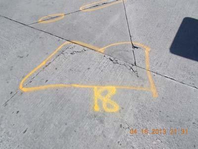


94 Concrete Apron Area 1 PHOTO NO. 13 PHOTO NO. 14 PHOTO NO. 15 PHOTO NO. 16 PHOTO NO. 17 PHOTO NO. 18 PHOTO NO. 19 PHOTO NO. 20 PHOTO NO. 21 PHOTO NO. 22 PHOTO NO. 23 PHOTO NO. 24


95 Concrete Apron Area 1 PHOTO NO. 25 PHOTO NO. 26 PHOTO NO. 27 PHOTO NO. 28 PHOTO NO. 29 PHOTO NO. 30 PHOTO NO. 31 PHOTO NO. 32 PHOTO NO. 33 PHOTO NO. 34 PHOTO NO. 35 PHOTO NO. 36


96 Concrete Apron Area 1 PHOTO NO. 37 PHOTO NO. 38 PHOTO NO. 39 PHOTO NO. 40 PHOTO NO. 41 PHOTO NO. 42 PHOTO NO. 43 PHOTO NO. 44 PHOTO NO. 45 PHOTO NO. 46 PHOTO NO. 47 PHOTO NO. 48


97 Concrete Apron Area 1 PHOTO NO. 49 PHOTO NO. 50 PHOTO NO. 51 PHOTO NO. 52 PHOTO NO. 53 PHOTO NO. 54 PHOTO NO. 55 PHOTO NO. 56 PHOTO NO. 57 PHOTO NO. 58 PHOTO NO. 59 PHOTO NO. 60


98 Concrete Apron Area 1 PHOTO NO. 61 PHOTO NO. 62 PHOTO NO. 63 PHOTO NO. 64 PHOTO NO. 65 PHOTO NO. 66 PHOTO NO. 67 PHOTO NO. 68 PHOTO NO. 69 PHOTO NO. 70 PHOTO NO. 71 PHOTO NO. 72


99 Concrete Apron Area 1 PHOTO NO. 73 PHOTO NO. 74 PHOTO NO. 75 PHOTO NO. 76 PHOTO NO. 77 PHOTO NO. 78 PHOTO NO. 79 PHOTO NO. 80


100 Concrete Apron Area 2 PHOTO NO. 1 PHOTO NO. 2 PHOTO NO. 3 PHOTO NO. 4 PHOTO NO. 5 PHOTO NO. 6 PHOTO NO. 7 PHOTO NO. 8 PHOTO NO. 9 PHOTO NO. 10 PHOTO NO. 11 PHOTO NO. 12


101 Concrete Apron Area 2 PHOTO NO. 13 PHOTO NO. 14 PHOTO NO. 15 PHOTO NO. 16 PHOTO NO. 17 PHOTO NO. 18 PHOTO NO. 19 PHOTO NO. 20 PHOTO NO. 21 PHOTO NO. 22 PHOTO NO. 23 PHOTO NO. 24


102 Concrete Apron Area 2 PHOTO NO. 25 PHOTO NO. 26 PHOTO NO. 27 PHOTO NO. 28 PHOTO NO. 29 PHOTO NO. 30 PHOTO NO. 31 PHOTO NO. 32 PHOTO NO. 33 PHOTO NO. 34 PHOTO NO. 35 PHOTO NO. 36


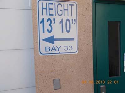


103 Concrete Apron Area 2 PHOTO NO. 37 PHOTO NO. 38 PHOTO NO. 39 PHOTO NO. 40 PHOTO NO. 41 PHOTO NO. 42 PHOTO NO. 43 PHOTO NO. 44 PHOTO NO. 45 PHOTO NO. 46 PHOTO NO. 47 PHOTO NO. 48


104 Concrete Apron Area 2 PHOTO NO. 49 PHOTO NO. 50 PHOTO NO. 51 PHOTO NO. 52 PHOTO NO. 53 PHOTO NO. 54 PHOTO NO. 55 PHOTO NO. 56 PHOTO NO. 57 PHOTO NO. 58 PHOTO NO. 59 PHOTO NO. 60


105 Concrete Apron Area 2 PHOTO NO. 61 PHOTO NO. 62 PHOTO NO. 63 PHOTO NO. 64 PHOTO NO. 65 PHOTO NO. 66 PHOTO NO. 67 PHOTO NO. 68 PHOTO NO. 69 PHOTO NO. 70 PHOTO NO. 71 PHOTO NO. 72


106 Concrete Apron Area 2 PHOTO NO. 73 PHOTO NO. 74 PHOTO NO. 75 PHOTO NO. 76 PHOTO NO. 77 PHOTO NO. 78 PHOTO NO. 79 PHOTO NO. 80 PHOTO NO. 81 PHOTO NO. 82 PHOTO NO. 83 PHOTO NO. 84


107 Concrete Apron Area 2 PHOTO NO. 85 PHOTO NO. 86 PHOTO NO. 87 PHOTO NO. 88


108 PHOTO NO. 1 Concrete Apron Area 3 PHOTO NO. 2 PHOTO NO. 3 PHOTO NO. 4 PHOTO NO. 5 PHOTO NO. 6 PHOTO NO. 7 PHOTO NO. 8 PHOTO NO. 9 PHOTO NO. 10 PHOTO NO. 11 PHOTO NO. 12


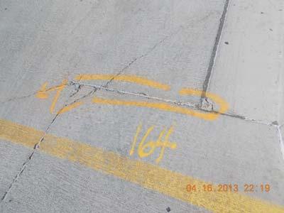


109 Concrete Apron Area 3 PHOTO NO. 13 PHOTO NO. 14 PHOTO NO. 15 PHOTO NO. 16 PHOTO NO. 17 PHOTO NO. 18 PHOTO NO. 19 PHOTO NO. 20 PHOTO NO. 21 PHOTO NO. 22 PHOTO NO. 23 PHOTO NO. 24


110 Concrete Apron Area 3 PHOTO NO. 25 PHOTO NO. 26 PHOTO NO. 27 PHOTO NO. 28 PHOTO NO. 29 PHOTO NO. 30 PHOTO NO. 31 PHOTO NO. 32 PHOTO NO. 33 PHOTO NO. 34


111 Concrete Apron Area 4 PHOTO NO. 1 PHOTO NO. 2 PHOTO NO. 3 PHOTO NO. 4 PHOTO NO. 5 PHOTO NO. 6 PHOTO NO. 7 PHOTO NO. 8 PHOTO NO. 9 PHOTO NO. 10 PHOTO NO. 11 PHOTO NO. 12


112 Concrete Apron Area 4 PHOTO NO. 13 PHOTO NO. 14 PHOTO NO. 15 PHOTO NO. 16 PHOTO NO. 17 PHOTO NO. 18 PHOTO NO. 19 PHOTO NO. 20 PHOTO NO. 21 PHOTO NO. 22 PHOTO NO. 23 PHOTO NO. 24


113 Concrete Apron Area 4 PHOTO NO. 25 PHOTO NO. 26 PHOTO NO. 27 PHOTO NO. 28 PHOTO NO. 29 PHOTO NO. 30 PHOTO NO. 31 PHOTO NO. 32 PHOTO NO. 33 PHOTO NO. 34 PHOTO NO. 35 PHOTO NO. 36


114 Concrete Apron Area 4 PHOTO NO. 37 PHOTO NO. 38 PHOTO NO. 39 PHOTO NO. 40 PHOTO NO. 41 PHOTO NO. 42 PHOTO NO. 43 PHOTO NO. 44 PHOTO NO. 45 PHOTO NO. 46 PHOTO NO. 47 PHOTO NO. 48


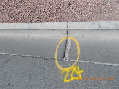


115 Concrete Apron Area 4 PHOTO NO. 49 PHOTO NO. 50 PHOTO NO. 51 PHOTO NO. 52 PHOTO NO. 53 PHOTO NO. 54 PHOTO NO. 55 PHOTO NO. 56 PHOTO NO. 57


116 Concrete Apron Area 5 PHOTO NO. 1 PHOTO NO. 2 PHOTO NO. 3 PHOTO NO. 4 PHOTO NO. 5 PHOTO NO. 6 PHOTO NO. 7 PHOTO NO. 8 PHOTO NO. 9 PHOTO NO. 10 PHOTO NO. 11 PHOTO NO. 12


117 Concrete Apron Area 5 PHOTO NO. 13 PHOTO NO. 14 PHOTO NO. 15 PHOTO NO. 16 PHOTO NO. 17 PHOTO NO. 18 PHOTO NO. 19 PHOTO NO. 20 PHOTO NO. 21 PHOTO NO. 22 PHOTO NO. 23 PHOTO NO. 24


118 Concrete Apron Area 5 PHOTO NO. 25 PHOTO NO. 26 PHOTO NO. 27 PHOTO NO. 28 PHOTO NO. 29 PHOTO NO. 30 PHOTO NO. 31 PHOTO NO. 32 PHOTO NO. 33 PHOTO NO. 34 PHOTO NO. 35 PHOTO NO. 36


119 Concrete Apron Area 5 PHOTO NO. 37 PHOTO NO. 38 PHOTO NO. 39 PHOTO NO. 40 PHOTO NO. 41 PHOTO NO. 42 PHOTO NO. 43 PHOTO NO. 44 PHOTO NO. 45 PHOTO NO. 46 PHOTO NO. 47 PHOTO NO. 48


120 Concrete Apron Area 5 PHOTO NO. 49 PHOTO NO. 50 PHOTO NO. 51 PHOTO NO. 52 PHOTO NO. 53 PHOTO NO. 54 PHOTO NO. 55 PHOTO NO. 56 PHOTO NO. 57 PHOTO NO. 58 PHOTO NO. 59 PHOTO NO. 60


121 Concrete Apron Area 5 PHOTO NO. 61 PHOTO NO. 62 PHOTO NO. 63 PHOTO NO. 64 PHOTO NO. 65 PHOTO NO. 66 PHOTO NO. 67 PHOTO NO. 68 PHOTO NO. 69 PHOTO NO. 70 PHOTO NO. 71 PHOTO NO. 72


122 Concrete Apron Area 5 PHOTO NO. 73 PHOTO NO. 74 PHOTO NO. 75 PHOTO NO. 76 PHOTO NO. 77 PHOTO NO. 78 PHOTO NO. 79 PHOTO NO. 80 PHOTO NO. 81 PHOTO NO. 82 PHOTO NO. 83 PHOTO NO. 84


123 Concrete Apron Area 5 PHOTO NO. 85 PHOTO NO. 86 PHOTO NO. 87 PHOTO NO. 88 PHOTO NO. 89 PHOTO NO. 90 PHOTO NO. 91 PHOTO NO. 92 PHOTO NO. 93 PHOTO NO. 94 PHOTO NO. 95 PHOTO NO. 96

124 Concrete Apron Area 5 PHOTO NO. 97


125 Concrete Apron Area 6 PHOTO NO. 1 PHOTO NO. 2 PHOTO NO. 3 PHOTO NO. 4 PHOTO NO. 5 PHOTO NO. 6 PHOTO NO. 7 PHOTO NO. 8 PHOTO NO. 9 PHOTO NO. 10 PHOTO NO. 11 PHOTO NO. 12


126 Concrete Apron Area 6 PHOTO NO. 13 PHOTO NO. 14 PHOTO NO. 15 PHOTO NO. 16 PHOTO NO. 17 PHOTO NO. 18 PHOTO NO. 19 PHOTO NO. 20 PHOTO NO. 21 PHOTO NO. 22 PHOTO NO. 23 PHOTO NO. 24


127 Concrete Apron Area 6 PHOTO NO. 25 PHOTO NO. 26 PHOTO NO. 27 PHOTO NO. 28 PHOTO NO. 29 PHOTO NO. 30 PHOTO NO. 31 PHOTO NO. 32 PHOTO NO. 33 PHOTO NO. 34 PHOTO NO. 35 PHOTO NO. 36


128 Concrete Apron Area 6 PHOTO NO. 37 PHOTO NO. 38 PHOTO NO. 39 PHOTO NO. 40 PHOTO NO. 41 PHOTO NO. 42 PHOTO NO. 43 PHOTO NO. 44 PHOTO NO. 45 PHOTO NO. 46 PHOTO NO. 47 PHOTO NO. 48


129 Concrete Apron Area 6 PHOTO NO. 49 PHOTO NO. 50 PHOTO NO. 51 PHOTO NO. 52 PHOTO NO. 53 PHOTO NO. 54 PHOTO NO. 55 PHOTO NO. 56 PHOTO NO. 57 PHOTO NO. 58 PHOTO NO. 59 PHOTO NO. 60


130 Concrete Apron Area 6 PHOTO NO. 61 PHOTO NO. 62 PHOTO NO. 63 PHOTO NO. 64 PHOTO NO. 65 PHOTO NO. 66 PHOTO NO. 67 PHOTO NO. 68 PHOTO NO. 69 PHOTO NO. 70 PHOTO NO. 71 PHOTO NO. 72


131 Concrete Apron Area 6 PHOTO NO. 73 PHOTO NO. 74 PHOTO NO. 75 PHOTO NO. 76 PHOTO NO. 77 PHOTO NO. 78 PHOTO NO. 79 PHOTO NO. 80 PHOTO NO. 81 PHOTO NO. 82 PHOTO NO. 83 PHOTO NO. 84


132 Concrete Apron Area 6 PHOTO NO. 85 PHOTO NO. 86 PHOTO NO. 87 PHOTO NO. 88 PHOTO NO. 89 PHOTO NO. 90 PHOTO NO. 91 PHOTO NO. 92 PHOTO NO. 93 PHOTO NO. 94 PHOTO NO. 95 PHOTO NO. 96


133 Concrete Apron Area 6 PHOTO NO. 97 PHOTO NO. 98 PHOTO NO. 99 PHOTO NO. 100 PHOTO NO. 101 PHOTO NO. 102 PHOTO NO. 103 PHOTO NO. 104 PHOTO NO. 105 PHOTO NO. 106 PHOTO NO. 107 PHOTO NO. 108


134 Concrete Apron Area 6 PHOTO NO. 109 PHOTO NO. 110 PHOTO NO. 111 PHOTO NO. 112 PHOTO NO. 113 PHOTO NO. 114 PHOTO NO. 115 PHOTO NO. 116 PHOTO NO. 117 PHOTO NO. 118 PHOTO NO. 119 PHOTO NO. 120


135 Concrete Apron Area 6 PHOTO NO. 121 PHOTO NO. 122 PHOTO NO. 123
VAE VIEW ELEMENTARY WINDOW REPLACEMENT West 1600 North Layton, UT Specifications. Construction Documents
 VAE VIEW ELEMENTARY WINDOW REPLACEMENT 1750 West 1600 North Layton, UT 84041 Specifications 19 March 2018 TABLE OF CONTENTS DIVISION 00 PREREQUIREMENT AND CONTRACTING REQUIREMENTS A101 A201 A310 A312 G701
NORTHWESTERN UNIVERSITY PROJECT NAME JOB # ISSUED: 03/29/2017
 SECTION 01 3100 - PROJECT MANAGEMENT AND COORDINATION PART 1 - GENERAL 1.1 RELATED DOCUMENTS A. Drawings and general provisions of the Contract, including General and Supplementary Conditions and other
SECTION PRODUCT REQUIREMENTS PART 1 - GENERAL 1.1 RELATED DOCUMENTS
 SECTION 01600 - PRODUCT REQUIREMENTS PART 1 - GENERAL 1.1 RELATED DOCUMENTS A. Drawings and general provisions of the Contract, including General and Supplementary Conditions and other Division 1 Specification
MASTERSPEC TECHNICAL SPECIFICATIONS DIVISION 01 GENERAL REQUIREMENTS
 SECTION 016000 - PRODUCT REQUIREMENTS PART 1 - GENERAL 1.1 SUMMARY A. This Section includes administrative and procedural requirements for selection of products for use in Project; product delivery, storage,
George Washington Middle School - HVAC Replacement 100% Construction Documents May 7, 2018 TABLE OF CONTENTS
 TABLE OF CONTENTS DIVISION 01 GENERAL REQUIREMENTS 011000 SUMMARY 012500 SUBSTITUTION PROCEDURES 012900 PAYMENT PROCEDURES 013100 PROJECT MANAGEMENT AND COORDINATION 013200 CONSTRUCTION PROGRESS DOCUMENTATION
RANDOLPH COMMUNITY CENTER GYMNASIUM FLOOR REPLACEMENT
 PROJECT MANUAL RANDOLPH COMMUNITY CENTER GYMNASIUM FLOOR REPLACEMENT CITY OF RICHMOND Richmond, Virginia Architect s Project No. 563107 ARCHITECT/ENGINEER RICHMOND, VIRGINIA A/E s Project No. 563107 set
TRUMAN STATE UNIVERSITY SITE IMPROVEMENTS, KIRK BLDG, MISSOURI HALL & STUDENT REC CENTER LTD RENOVATIONS
 SECTION 011000 - SUMMARY PART 1 - GENERAL 1.1 RELATED DOCUMENTS A. Drawings and general provisions of the Contract, including General and Supplementary Conditions and other Division 01 Specification Sections,
SECTION PAYMENT PROCEDURES
 SECTION 012900 PART 1 GENERAL 1.1 RELATED DOCUMENTS A. Drawings and general provisions of the Contract including General and Supplementary Conditions and other Division 01 Specifications Sections apply
SSM Project: Centennial School District Issued for Bid AC Unit Replacements 05/16/2014 Klinger and Log College Middle Schools
 Division Section Title SPECIFICATIONS GROUP General Requirements Subgroup DIVISION 01 GENERAL REQUIREMENTS 011000 SUMMARY 012500 SUBSTITUTION PROCEDURES 012600 CONTRACT MODIFICATION PROCEDURES 012900 PAYMENT
PROJECT MANUAL POINT BLANK RANGE & GUN SHOP. 600 Corporate way Knoxville, TN. Bid/Permit Set
 PROJECT MANUAL POINT BLANK RANGE & GUN SHOP 600 Corporate way Knoxville, TN Bid/Permit Set Division Section Title SPECIFICATIONS GROUP DIVISION 01 - GENERAL REQUIREMENTS 011000 SUMMARY 012600 CONTRACT
DIVISION 10 - SPECIALTIES Toilet, Bath, and Laundry Accessories Fire Extinguishers
 DIVISION 01 GENERAL REQUIREMENTS 012500 Substitution Procedures 012600 Contract Modification Procedures 013100 Project Management and Coordination 013150 Requests for Information 013200 Construction Progress
New Mexico State University Herritage Farm Interpretive Trail
 PROJECT MANUAL PROJECT MANAGER: SHELLEY ZIVKOVICH 575-646-1991 shelleyz@nmsu.edu New Mexico State University Herritage Farm Interpretive Trail APRIL 28, 2017 PROJECT #206-88 WDG ARCHITECTS 1014 South Main
OSNI PONCA OFFICE REMODEL
 OSNI PONCA OFFICE REMODEL PROJECT MANUAL OCTOBER 2016 SCHEMMER PROJECT NO. 06571.002 OSNI PONCA OFFICE REMODEL TABLE OF CONTENTS DIVISION 00 - PROCUREMENT AND CONTRACTING REQUIREMENTS 000115 LIST OF DRAWING
CITY OF RICHMOND EDI BUILDING WINDOW REPLACEMENT PROJECT MANUAL. Commonwealth Architects
 CITY OF RICHMOND EDI BUILDING WINDOW REPLACEMENT 701 North 25th Street Richmond, Virginia 23223 PROJECT MANUAL PERMIT SET FEBRUARY 27, 2017 Commonwealth Architects 101 Shockoe Slip Richmond, VA 23219 CITY
CITY OF RICHMOND EDI BUILDING WINDOW REPLACEMENT 701 North 25th Street Richmond, Virginia PROJECT MANUAL BID SET April 4, 2018
 CITY OF RICHMOND EDI BUILDING WINDOW REPLACEMENT 701 North 25th Street Richmond, Virginia 23223 PROJECT MANUAL BID SET April 4, 2018 Commonwealth Architects 101 Shockoe Slip, Fl 3 Richmond, VA 23219 CITY
RWA, Inc. TECHNICAL SPECIFICATIONS NORTH COLLIER BOULEVARD PAVING AND DRAINAGE IMPROVEMENTS Willow Park Drive Suite 200 Naples, FL 34109
 RWA, Inc. TECHNICAL SPECIFICATIONS NORTH COLLIER BOULEVARD PAVING AND DRAINAGE IMPROVEMENTS 6610 Willow Park Drive Suite 200 Naples, FL 34109 MAY 23, 2012 NORTH COLLIER BOULEVARD PAVING AND DRAINAGE IMPROVEMENTS
CHAPEL HILL TOWN HALL RENOVATIONS UPPER LEVEL, SOUTH CHAPEL HILL, NORTH CAROLINA
 SECTION 011000 - SUMMARY PART 1 - GENERAL 1.1 RELATED DOCUMENTS A. Drawings and general provisions of the Contract, including General and Supplementary Conditions and other Division 01 Specification Sections,
SPECIFICATIONS. Permit Set RICHMOND CITY HALL: SUITE 110 RENOVATIONS. City of Richmond, Virginia Architect s Project No
 SPECIFICATIONS Permit Set RICHMOND CITY HALL: SUITE 110 RENOVATIONS ARCHITECT RICHMOND, VIRGINIA MECHANICAL, PLUMBING, FIRE PROTECTION, AND ELECTRICAL ENGINEERS GLEN ALLEN, VIRGINIA A/E s Project No. 563109
INVITATION FOR BIDS FOR
 ********************************************************************************************** IFB NO. Y18-749-RM ISSUED: March 16, 2018 INVITATION FOR BIDS FOR EAST ORANGE HEAD START MODULAR RELOCATION
County of Elko, Nevada Requirements, Specifications and Contract Documents. Mechanical System Upgrade, Project Manuel. Jackpot, Elko County, Nevada
 1 County of Elko, Nevada Requirements, Specifications and Contract Documents for Jackpot Recreation Center Mechanical System Upgrade 2016 Project in Jackpot, Elko County, Nevada Department of Community
SPECIFICATIONS May 25, Ellicott Station Redevelopment Brewery Building - 40 Ellicott Street Ellicott Street Batavia, New York United States
 SPECIFICATIONS May 25, 2018 Ellicott Station Redevelopment Brewery Building - 40 Ellicott Street Ellicott Street Batavia, New York United States Ellicott Station Development, LLC 500 Seneca Street Suite
DeKalb County Library Dunwoody Library Staff Area Renovation
 PROJECT MANUAL DeKalb County Library Dunwoody Library Staff Area Renovation OWNER: DeKalb County Library Email: kimbroj@dekalblibrary.org Contact: Jackee Kimbro 404-508-719-, ext. 2236 ARCHITECT: MEP ENGINEER:
SPECIFICATIONS. September 27, 2016 Bid Set
 SPECIFICATIONS September 27, 2016 Bid Set CITY HALL SUITE 100 & 102 RENOVATIONS TABLE OF CONTENTS (Refer to Project Book under separate cover for additional requirements) SPECIFICATIONS DIVISION 1 - GENERAL
University Apartments on Brooklyn PROJECT MANUAL
 Section 011000 - Summary PART 1 - GENERAL 1.1 SUMMARY A. Section Includes: 1. Project information. 2. Work covered by Contract Documents. 3. Phased construction. 4. Work under separate contracts. 5. Access
TOWNES + architects, P.A.
 TOWNES + architects, P.A. 2421 North 12th Avenue, Pensacola, Florida 32503 Telephone: (850) 433-0203 Florida Registration AA-26001051 PROJECT MANUAL City of Pensacola Fleet Maintenace Garage Re ovation
SECTION PRODUCT REQUIREMENTS PART 1 GENERAL 1.1 RELATED DOCUMENTS
 SECTION 01 60 00 PRODUCT REQUIREMENTS PART 1 GENERAL 1.1 RELATED DOCUMENTS A. Drawings and general provisions of the Contract, including General and Supplementary Conditions and other Division 01 Specification
University of Oklahoma Sarkeys Energy Center Atriums Waterproofing Project mass project no Set no. project manual.
 University of Oklahoma Sarkeys Energy Center Atriums Waterproofing Project mass project no. 1801.01 07 12 2018 Set no. project manual. University of Oklahoma Sarkeys Energy Center Atriums Waterproofing
Hard Rock Hotel and Casino - Tulsa Casino 3 and Suite Hotel Exterior Painting Bid Issue Issue Date: 18 March 2013 Project Number
 Hard Rock Hotel and Casino - Tulsa Casino 3 and Suite Hotel Exterior Painting Issue Date: 18 March 2013 Project Number 13-201.1 9400 Gateway Drive, Suite B Reno, NV 89521 775.852.3977 (p) 775.852.6543
ENTRY SECURITY MODIFICATIONS
 Rio Rancho Public Schools ENTRY SECURITY MODIFICATIONS Volume 2 of 2 Divisions 01 through 28 Mountain View Middle School Project Number 083105-16-002 Rio Rancho Cyber Academy Project Number 083018-16-001
GADSDEN ELEMENTARY SCHOOL PHOTOVOLTAIC SYSTEM PROJECT
 GADSDEN ELEMENTARY SCHOOL PHOTOVOLTAIC SYSTEM PROJECT JUNE 13, 2018 PROJECT MANUAL SAVANNAH-CHATHAM COUNTY PUBLIC SCHOOL SYSTEM DULOHERY WEEKS GADSDEN ELEMENTARY SCHOOL PHOTOVOLTAIC SYSTEM PROJECT TABLE
AWT 9TH FLOOR IMPROVEMENTS CITY OF ANAHEIM, CALL CENTER CREDIT & BILLING DEPARTMENTS, ANAHEIM, CA TECHNICAL SPECIFICATIONS AUGUST 2, 2018
 CITY OF ANAHEIM, CALL CENTER CREDIT & BILLING DEPARTMENTS, ANAHEIM, CA TECHNICAL SPECIFICATIONS AUGUST 2, 2018 ROBERT BORDERS & ASSOCIATES. General Conditions AIA A201 by reference. TABLE OF CONTENTS DIVISION
AWT 2ND FLOOR IMPROVEMENTS CITY OF ANAHEIM, HOUSING AUTHORITY & WORKPLACE, ANAHEIM, CA TECHNICAL SPECIFICATIONS OCTOBER 24, 2017
 CITY OF ANAHEIM, HOUSING AUTHORITY & WORKPLACE, ANAHEIM, CA TECHNICAL SPECIFICATIONS OCTOBER 24, 2017 ROBERT BORDERS & ASSOCIATES. General Conditions AIA A201 by reference. TABLE OF CONTENTS DIVISION 1
1ARCHITECTURE TABLE OF CONTENTS
 TABLE OF CONTENTS DIVISION 00 - PROCUREMENT AND CONTRACTING REQUIREMENTS 00 0102 COVER 00 0107 SEALS PAGE 00 0111 TABLE OF CONTENTS DIVISION 01 - GENERAL REQUIREMENTS 01 1000 01 2000 01 2100 01 2300 01
CONTRACTOR S PROPOSAL
 WEST VIRGINIA DEPARTMENT OF TRANSPORTATION DIVISION OF HIGHWAYS ALL ITEMS MUST BE COMPLETED BY CONTRACTOR CALL NUMBER CONTRACTOR S NAME CONTRACTOR S FEIN BID AMOUNT DBE GOAL (%) WV LICENSE NUMBER PREQUALIFICATION
RICHMOND PUBLIC SCHOOLS
 PROJECT MANUAL RICHMOND PUBLIC SCHOOLS NEW MIDDLE SCHOOL CONSTRUCTION ON HULL STREET CONSTRUCTION PROJECT DEPT. OF EDUCATION NO. 123-108-00-100 DIVISION 1 (DRAFT SPECIFICATIONS) PREPARED BY RRMM ARCHITECTS
Ogden Regional Medical Center Courtyard Remodel. Construction Documents. MountainStar Healthcare PROJECT MANUAL FOR
 PROJECT MANUAL FOR Ogden Regional Medical Center 5475 South 500 East Ogden, UT 84405 for MountainStar Healthcare Construction Documents NJRA Architects, Inc. 5272 South College Dr. Murray, Utah 84123 Telephone:
NMSU Carlsbad Campus Main Building and Computer Building DDC Control Upgrade. Project Manual Technical Specifications Review Submittal May 12, 2017
 NMSU Carlsbad Campus Main Building and Computer Building DDC Control Upgrade NMSU Facilities and Services Department P.O. Box 30001 Las Cruces, NM 88003-8001 Project Manual Technical Specifications Review
RICHMOND PUBLIC SCHOOLS
 PROJECT MANUAL RICHMOND PUBLIC SCHOOLS E.S.H. GREENE ELEMENTARY SCHOOL CONSTRUCTION PROJECT DEPT. OF EDUCATION NO. 123-144-00-100 DIVISION 1 (DRAFT SPECIFICATIONS) PREPARED BY RRMM ARCHITECTS ARCHITECTURE
THE FORUM ROME, GEORGIA FOR FLOYD COUNTY PROJECT MANUAL (BALLROOM AND CONCESSIONS) Construction Documents
 Construction Documents") THE FORUM ROME, GEORGIA FOR FLOYD COUNTY PROJECT MANUAL (BALLROOM AND CONCESSIONS) Construction Documents Architect s Project Number: 420.01.01 Issued: November 11, 2016 PEACOCK a r c h i t e c t s 5525
THE FORUM ROME, GEORGIA FOR FLOYD COUNTY PROJECT MANUAL (BALLROOM AND CONCESSIONS) Construction Documents Architect s Project Number: 420.01.01 Issued: November 11, 2016 PEACOCK a r c h i t e c t s 5525
1. Section "Temporary Facilities and Controls" for limitations and procedures governing temporary use of Owner's facilities.
 CSB 7th Floor Orthopaedic Surgery Office Renovation Phase 2 SECTION 011000 - SUMMARY PART 1 - GENERAL 1.1 RELATED DOCUMENTS A. Drawings and general provisions of the Contract, including General and Supplementary
LCCC MAIN PLANT BOILER BURNER UPGRADES
 LCCC MAIN PLANT BOILER BURNER UPGRADES FOR Laramie County Community College (LCCC) 1400 East College Drive Cheyenne, WY 82007 ENGINEERS Cator, Ruma & Associates 420 West Lincolnway Cheyenne, WY 82001 PROJECT
Southwest Middle School 6030 Ogeechee Road, Savannah Georgia
 Southwest Middle School 6030 Ogeechee Road, Savannah Georgia Savannah Chatham County Public School System Savannah, GA Bid C18-01 May 2017 Barnard Architects 220 East Hall Street, Savannah GA 31410 Southwest
SPECIFICATIONS VOLUME II August 26, 2016
 SPECIFICATIONS VOLUME II August 26, 2016 Savannah Chatham County Public School System Charles Ellis Montessori Academy 220 East 49 th Street Savannah Ga 31406 FACILITY NUMBER 625-4054 BY: LS3P/Dawson 321
SECTION GENERAL REQUIREMENTS PART 1 - GENERAL I 1 GENERAL REQUIRMENTS
 SECTION 01 00 00 GENERAL REQUIREMENTS PART 1 - GENERAL 1.1 SECTION INCLUDES A. Summary of Work: 1. General 2. Contract. B. Contract Considerations: 1. Schedule of values. 2. Applications for payment. 3.
Project Manual. Beaverton School District Beaverton High School Gymnasium Improvement Beaverton, Oregon. Issue date: December 21st 2017
 Project Manual Beaverton School District Beaverton High School Gymnasium Improvement Beaverton, Oregon Issue date: December 21st 2017 18241 Beaverton High School Gymnasium Improvement TABLE OF CONTENTS
BOWIE STATE UNIVERSITY CAR PARKING LOT
 BOWIE STATE UNIVERSITY CAR PARKING LOT TECHNICAL SPECIFICATIONS 100% CD SUBMISSION NOVEMBER 2, 2018 Prepared by WHITNEY, BAILEY COX & MAGNANI, LLC 300 East Joppa Road, Suite 200 Baltimore, Maryland 21286
Baseball Performance Development Center A Prevailing Wage Project
 June 30, 2016 Baseball Performance Development Center A Prevailing Wage Project PROJECT MANUAL Owner CENTRAL MICHIGAN UNIVERISTY 206 Combined Services Building Mount Pleasant, Michigan PROJECT NUMBER 15-231
ANTELOPE VALLEY COLLEGE PALMDALE AIRPORT TERMINAL REMODEL
 PALMDALE AIRPORT TERMINAL REMODEL 21000 20 TH STREET EAST, PALMDALE, CA 93550 for ANTELOPE VALLEY COMMUNITY COLLEGE DISTRICT 3041 WEST AVENUE K LANCASTER, CALIFORNIA 93536-5436 PROJECT MANUAL AUGUST 15,
PROJECT MANUAL UNIVERSITY HALL BOILER REPLACEMENT PROJECT NO. EM 610
 PROJECT MANUAL For UNIVERSITY HALL BOILER REPLACEMENT PROJECT NO. EM 610 Prepared For: UNIVERSITY OF COLORADO AT COLORADO SPRINGS September 27, 2010 Prepared By: SCHENDT ENGINEERING CORP. 2912 Beacon Street
ISU Liberal Arts Chiller Replacement DPW # February 2018
 SECTION 01 1000 - SUMMARY PART 1 GENERAL 1.01 PROJECT A. Project Name: DPW 18223 ISU Liberal Arts Chiller Replacement. B. Owner's Name: Idaho State University (ISU) / State of Idaho. C. Engineer's Name:
1.4 USE OF EXISTING ELEVATORS FOR CONSTRUCTION PURPOSES (NO ELEVATOR CONTRACTOR IS CONTRACTED FOR THE PROJECT)
") 1.4 USE OF EXISTING ELEVATORS FOR CONSTRUCTION PURPOSES (NO ELEVATOR CONTRACTOR IS CONTRACTED FOR THE PROJECT) The use of an existing elevator during construction shall be strictly prohibited. Any deviation
1.4 USE OF EXISTING ELEVATORS FOR CONSTRUCTION PURPOSES (NO ELEVATOR CONTRACTOR IS CONTRACTED FOR THE PROJECT) The use of an existing elevator during construction shall be strictly prohibited. Any deviation
Document B252TM 2007
 Document B252TM 2007 Standard Form of Architect s Services: Architectural Interior Design for the following PROJECT: (Name and location or address) This document has important legal consequences. Consultation
PARKING LOTS 4 AND 5 (DEMOLITION)
") TECHNICAL SPECIFICATIONS PARKING LOTS 4 AND 5 (DEMOLITION) AT 9200 Valley View Street Cypress, CA 90630 1830 Romneya Drive Anaheim, CA 92801-1819 Tel. (714) 808-4747 WW Project No. 17030.00 October 25,
TECHNICAL SPECIFICATIONS PARKING LOTS 4 AND 5 (DEMOLITION) AT 9200 Valley View Street Cypress, CA 90630 1830 Romneya Drive Anaheim, CA 92801-1819 Tel. (714) 808-4747 WW Project No. 17030.00 October 25,
PROJECT SPECIFICATIONS PENSACOLA INTERNATIONAL AIRPORT PARKING GARAGE REHABILITATION
 PROJECT SPECIFICATIONS PENSACOLA INTERNATIONAL AIRPORT PARKING GARAGE REHABILITATION CITY OF PENSACOLA November 2018 SECTION 011000- SUMMARY OF WORK PART 1 - GENERAL 1.1 DOCUMENTS A. Drawings and general
NORTHWESTERN UNIVERSITY PROJECT NAME JOB # ISSUED: 03/29/2017
 SECTION 01 4000 - QUALITY REQUIREMENTS PART 1 - GENERAL 1.1 RELATED DOCUMENTS A. Drawings and general provisions of the Contract, including General and Supplementary Conditions and other Division 01 Specification
TCC/SHORE TRANSIT BUS MAINTENANCE FACILITY - PHASE II
 SECTION 013200 - CONSTRUCTION PROGRESS DOCUMENTATION PART 1 - GENERAL 1.1 RELATED DOCUMENTS A. Drawings and general provisions of the Contract, including General and Supplementary Conditions and other
AIR CONDITIONING SYRACUSE JUNIOR HIGH SCHOOL
 PROJECT MANUAL FOR AIR CONDITIONING DAVIS SCHOOL DISTRICT 1450 S. 2000 W. Syracuse, UT 84075 January 2017 BLANK PAGE TABLE OF CONTENTS DIVISION 01 GENERAL CONDITIONS 01 1000 Summary 01 2900 Payment Procedures
1. This Section includes administrative and procedural requirements for contract closeout including, but not limited to, the following:
 SECTION 01700 - CONTRACT CLOSEOUT PART 1 - GENERAL 1.01 RELATED DOCUMENTS 1. Drawings and general provisions of the Contract, including General and Supplementary Conditions and other Division 1 Specification
1) Unified School District No. 489 reserves the right to reject any or all bids and to waive any informalities in the bid procedure.
 Unified School District No. 489 reserves the right to reject any or all bids and to waive any informalities in the bid procedure.") Prospective bidders: The Board of Education, Unified School District No. 489, will receive bids for the fabrication and construction of two pre-manufactured metal building in the designated area at the
Prospective bidders: The Board of Education, Unified School District No. 489, will receive bids for the fabrication and construction of two pre-manufactured metal building in the designated area at the
PROJECT MANUAL Volume 1. Project: Clayton Greenway System -Mark s Creek Bridge Replacement
 PROJECT MANUAL Volume 1 Project: Clayton Greenway System -Mark s Creek Bridge Replacement Owner: Town of Clayton Construction Manager: Lysaght & Associates Issued August 9, 2017 COVER SHEET 000000-1 TABLE
Project Manual OVERLAND PARK BRANCH & ESIS RELOCATION. for
 Project Manual OVERLAND PARK BRANCH & ESIS RELOCATION for Chubb Floor 4 34 Corporate Woods 10950 Grandview Drive Overland Park KS 66210 Issued for Bid & Permit July 18, 2016 SECTION 000110 TABLE OF CONTENTS
Project Manual. Unitarian Universalist Congregation of Princeton 50 Cherry Hill Road Princeton, New Jersey Lot: 11 Block: 5201
 Project Manual for Alterations & Building Addition to: Unitarian Universalist Congregation of Princeton 50 Cherry Hill Road Princeton, New Jersey Lot: 11 Block: 5201 SCHEMATIC DESIGN ISSUE NOT FOR CONSTRUCTION
PROJECT MANUAL. Phi Delta Theta Phase NW 13 th Street Corvallis, OR Varitone Architecture LLC
 PROJECT MANUAL Phi Delta Theta Phase 2 120 NW 13 th Street Corvallis, OR 97330 Varitone Architecture LLC 231 SW 2nd Ave. PO Box 3420 Albany, Oregon 97321 Project Contacts Owner Phi Delta Theta Chapter
ruby ridge terrace apartments
 p r o j e c t m a n u a l for: ruby ridge terrace apartments 550 South, 12th Street 89801 Re-Bid Package 01 May 14, 2014 TABLE OF CONTENTS 1. Title page 2. Table of Contents 3. Invitation to Bid 4. Bid
East Central College
 SECTION 013200 - CONSTRUCTION PROGRESS DOCUMENTATION PART 1 - GENERAL 1.1 RELATED DOCUMENTS A. Drawings and general provisions of the Contract, including General and Supplementary Conditions and other
Chapter 6, Construction
 Chapter 6, Construction CHAPTER CONTENTS 6.1 OWNER-CONTRACTOR AGREEMENT A. Preparation B. Owner Signature C. Award 6.2 PRE-CONSTRUCTION CONFERENCE A. Administration B. Attendees C. Pre-Construction Conference
WAYNE COMMUNITY COLLEGE SECTION
 WAYNE COMMUNITY COLLEGE SECTION 00-01-15 LIST OF DRAWING SHEETS SECTION 00-01-15 LIST OF DRAWING SHEETS 1.1 LIST OF DRAWINGS A. Drawings: Drawings consist of the Contract Drawings and other drawings listed
TRUMAN STATE UNIVERSITY BALDWIN HALL, PERSHING BLDG AND VIOLETTE HALL ROOFING & EXT. RENOV.
 SECTION 011000 - SUMMARY PART 1 - GENERAL 1.1 RELATED DOCUMENTS A. Drawings and general provisions of the Contract, including General and Supplementary Conditions and other Division 01 Specification Sections,
Façade Access Upgrade Project
 University of California Hastings College of Law Façade Access Upgrade Project 200 McAllister Street, San Francisco, CA 94102 Project Number 12042.04 ITB #56-0160 (Revised) August 20, 2015 PROJECT MANUAL
100% FINAL DESIGN DRAFT SPECIFICATIONS MAY 17, 2018
 100% FINAL DESIGN DRAFT SPECIFICATIONS MAY 17, 2018 TABLE OF CONTENTS DIVISION 1 - GENERAL REQUIREMENTS 10000 GENERAL CONDITIONS (Provided by Owner) 01110 SUMMARY OF WORK 01150 APPLICABLE STANDARDS 01305
Renovations for South Morrison Library 746 Adams Drive Newport News, Virginia
 Specifications Prepared by 22 Enterprise Parkway, Suite 200, Hampton, Virginia 23666 Project #13069 November 8, 2013 SECTION 00002 - PROJECT DIRECTORY Owner: Contact: Electrical Engineer: City of Newport
WEAVER MOUNTAIN FIRE STATION OPERATIONS BUILDING SOUTH HIGHWAY 89 WICKENBURG, AZ PROJECT NO. L140D00737 BUREAU OF LAND MANAGEMENT
 WEAVER MOUNTAIN FIRE STATION OPERATIONS BUILDING 33501 SOUTH HIGHWAY 89 WICKENBURG, AZ 85390 PROJECT NO. L140D00737 BUREAU OF LAND MANAGEMENT PROJECT SPECIFICATIONS VOLUME 1 U.S. DEPARTMENT OF THE INTERIOR
Specific requirements for individual units of work are included in the appropriate sections in Divisions 2 through 16.
 SECTION 01 77 00 - PROJECT CLOSE-OUT PART 1 - GENERAL DESCRIPTION OF REQUIREMENTS: Definitions: Project close-out is the term used to describe certain collective project requirements, indicating completion
Document B Standard Form of Agreement Between Owner and Architect, Construction Manager as Adviser Edition
 Document B132 2009 Standard Form of Agreement Between Owner and Architect, Construction Manager as Adviser Edition AGREEMENT made as of the in the year (In words, indicate day, month and year.) BETWEEN
SECTION CONSTRUCTION PROGRESS DOCUMENTATION
 SECTION 01 32 00 CONSTRUCTION PROGRESS DOCUMENTATION PART 1 - GENERAL 1.1 RELATED DOCUMENTS A. Drawings and general provisions of the Contract, including General and Supplementary Conditions and other
1997 Part 2. Document B141. Standard Form of Architect's Services: Design and Contract Administration TABLE OF ARTICLES
 TM Document B141 Standard Form of Architect's Services: Design and Contract Administration 1997 Part 2 TABLE OF ARTICLES 2.1 PROJECT ADMINISTRATION SERVICES 2.2 SUPPORTING SERVICES 2.3 EVALUATION AND PLANNING
PROJECT MANUAL VOLUME ONE EOP Project # August 17, 2018
 PROJECT MANUAL VOLUME ONE EOP Project # 201732 August 17, 2018 KCTCS System Office Renovation MECHANICAL ROOM EQUIPMENT DEMOLITION 300 N. Main St. Versailles, Kentucky 40383 ARCHITECT EOP Architects 201
Multi-Institutional Academic Health Science & Research Center Evansville, IN
 SECTION 019113 - GENERAL COMMISSIONING REQUIREMENTS PART 1 - GENERAL 1.1 RELATED DOCUMENTS A. Drawings and general provisions of the Contract, including General and Supplementary Conditions and other Division
A. Project Identification: Wiggums Park Place Renovation. D. See Section Project Team List for additional information.
 SECTION 01 10 00 - SUMMARY PART 1 - GENERAL 1.1 SUMMARY A. Section Includes: 1. Project information. 2. Work covered by Contract Documents. 3. Specification and drawing conventions. 4. Miscellaneous provisions.
SECTION QUALITY REQUIREMENTS
 SECTION 014000 - PART 1 - GENERAL 1.1 SUMMARY A. Defines SRP requirements for Contractor Quality Control and Owner Quality Assurance. As an Electric and Water Utility, SRP has many critical facilities.
G , Request for Proposal Land Survey
 G601 1994, Request for Proposal Land Survey AIA Document G601 1994 allows owners to request proposals from a number of surveyors based on information deemed necessary by the owner and architect. G601 1994
APPENDIX D CONSTRUCTION PHASE CRITERIA
 A. GENERAL REQUIREMENTS CONSTRUCTION PHASE CRITERIA For the Construction Phase of the Project, the Architect/Engineer (A/E) is responsible for providing project administration for the Owner in accordance
QUALITY REQUIREMENTS
 SECTION 014000 - QUALITY REQUIREMENTS PART 1 - GENERAL 1.1 RELATED DOCUMENTS A. Drawings and general provisions of the Contract, including General and Supplementary Conditions and other Division 01 Specification
Richard B. Wilson K-8 School Roof Restoration
 Amphitheater Public Schools Richard B. Wilson K-8 School Roof Restoration BG Project No: 17.14.24 Construction Document Specifications Richard B. Wilson K-8 School Roof Restoration SPECIFICATIONS INDEX
Audio Sessions. Session 5 MEETINGS. Construction Contract Administration Education Program
 Audio Sessions Session 5 MEETINGS Education Program Certified Construction Contract Administrator (CCCA) Preparatory Course 2011 The Construction Specifications Institute www.csinet.org This presentation
ADDENDUM #1 FOR THE STUDENT SERVICES DEMOLITION WEST VALLEY COLLEGE
 ADDENDUM #1 FOR THE STUDENT SERVICES DEMOLITION AT WEST VALLEY COLLEGE Owner West Valley-Mission Community College District Saratoga, California Bid #07-1617 10-11-16 WEST VALLEY-MISSION COMMUNITY COLLEGE
Amphitheater High School Roof Replacement
 Amphitheater Public Schools Amphitheater High School Roof Replacement BG Project No: 17.14.06 Construction Document Specifications Amphitheater High School Roof Replacement SPECIFICATIONS INDEX DIVISION
1. Section "Temporary Facilities and Controls" for limitations and procedures governing temporary use of Owner's facilities.
 SECTION 011000 - SUMMARY PART 1 - GENERAL 1.1 RELATED DOCUMENTS A. Drawings and general provisions of the Contract, including General and Supplementary Conditions and other Division 01 Specification Sections,
A62 UT PRE-CONSTRUCTION MEETING AGENDA
 Provided below are the agenda items typically required by the Owner for the Pre-Construction Meeting. Guidance provided in agenda items does not revise the requirements of the Agreement. Instructions:
TABLE OF CONTENTS VOLUME 1. DIVISION 00 - INTRODUCTORY INFORMATION, BIDDING REQUIREMENTS, CONTRACT FORMS & CONDITIONS OF THE CONTRACT Pages
 TABLE OF CONTENTS VOLUME 1 DIVISION 00 - INTRODUCTORY INFORMATION, BIDDING REQUIREMENTS, CONTRACT FORMS & CONDITIONS OF THE CONTRACT Pages SCHEDULE OF DRAWINGS...... 1 PROJECT PERSONNEL & DIRECTORY......
University of South Florida Health Center MDL-0114 Building Reroofing USF Project No. PF
 University of South Florida Health Center MDL-0114 Building Reroofing USF Project No. PF154317843202 Project Manual October 31, 2017 October 31, 2017 Project Manual For University of South Florida Health
Coastal Carolina University RE-BID WILLIAMS BRICE RENOVATION AND REPAIR Conway, South Carolina
 Project Manual for Coastal Carolina University RE-BID WILLIAMS BRICE RENOVATION AND REPAIR Conway, South Carolina DWG Consulting Engineers 1009 Anna Knapp Blvd. Suite 202 Mt Pleasant, South Carolina 29464
REQUEST FOR PROPOSAL: Construction Management at Risk Services Hamilton International Air Cargo Logistics Facility. RFP Components
 REQUEST FOR PROPOSAL: Construction Management at Risk Services Hamilton International Air Cargo Logistics Facility RFP Components CLIENT: TradePort International Corporation, Operators of John C. Munro
HOLLOWAY HALL AUDITORIUM RENOVATION
 HOLLOWAY HALL AUDITORIUM RENOVATION BID DOCUMENTS PROJECT MANUAL JANUARY 2, 2013 SALISBURY UNIVERSITY FACILITIES PLANNING AND CAPITAL PROJECTS 1101 CAMDEN AVENUE SALISBURY, MARYLAND 21801 DESIGN COLLECTIVE,
DIVISION 1 GENERAL REQUIREMENTS SECTION PROJECT SCHEDULE
 DIVISION 1 GENERAL REQUIREMENTS SECTION 01 32 16 PART 1 - GENERAL 1.1 RELATED DOCUMENTS A. All drawings and technical specifications, Notice to Bidders, Instructions and Information to Bidders, Bid Proposal
A62 PRE-CONSTRUCTION MEETING AGENDA
 Provided below are the agenda items typically required by the Owner for the Pre-Construction Meeting. Guidance provided in agenda items does not revise the requirements of the Agreement. Instructions:
Appendix D University of Maine System. Supplementary Requirements to AIA Document B Standard Form of Architect s Services
 Appendix D University of Maine System Supplementary Requirements to AIA Document B201-2007 Standard Form of Architect s Services This document provides the Architect s scope of services only and must be
***Specifications***
 STEM 2 Greenhouse Project Bid No. B17-14 ***Specifications*** Bid RFI Questions Due: Tuesday, July 11, 2017 2:00PM Gale Stevens, Buyer gasteven@cabrillo.edu BID DOCUMENTS: GALE STEVENS, BUYER 831-477-5613
Telecommunications Rooms Electrical & Mechanical Upgrades CSM15-001C October 19, 2015 College of Southern Maryland SECTION SUMMARY
 PART 1 GENERAL 1.1 PROJECT SECTION 01 10 00 - SUMMARY A. Project Name: Telecommunications Rooms Electrical & Mechanical Upgrades B. Owner's Name:. C. The Project consists of upgrading existing, and the