Report of Preliminary Geotechnical Engineering Investigation for Ponds
|
|
|
- Benedict West
- 5 years ago
- Views:
Transcription
, Florida December 15, 2015 Geotechnical and Environmental Consultants, Inc. 919 Lake Baldwin Lane Orlando, FL 32814 HNTB Corporation 610 Crescent Executive Court Suite 400 Lake Mary, FL 32746")
1 Report of Preliminary Geotechnical Engineering Investigation for Ponds Segment 3: State Road 400 (SR 400)/Interstate 4 (I-4) from One Mile East of SR 434 to East of SR /US Seminole County (77160), Florida December 15, 2015 Geotechnical and Environmental Consultants, Inc. 919 Lake Baldwin Lane Orlando, FL HNTB Corporation 610 Crescent Executive Court Suite 400 Lake Mary, FL 32746
2 February 21, 2014 Revised April 30, 2015 Revised December 15, 2015 HNTB 610 Crescent Executive Court, Suite 400 Lake Mary, Florida Attention: Subject: Mr. Luis Diaz, P.E. Report of Preliminary Geotechnical Engineering Investigation for Ponds SR 400 (I-4) FROM US 27 TO KIRKMAN ROAD AND FROM E OF SR 434 TO SR 472 SEGMENT 3 Polk, Osceola, Orange, Seminole and Volusia Counties, Florida FPN GEC Project No. 3492G Dear Mr. Diaz: Geotechnical and Environmental Consultants, Inc. (GEC) is pleased to provide this Report of Preliminary Geotechnical Engineering Investigation for Ponds for the above-referenced project. This revised report incorporates the combination of Swales 313A, B, and C into one new combined Swale 313A. The purpose of this investigation was to evaluate soil and groundwater conditions at the proposed pond locations and develop preliminary geotechnical engineering recommendations to aid in the initial planning and design of the ponds. This report describes our exploration procedures, exhibits the data obtained and presents our preliminary conclusions and recommendations regarding the geotechnical engineering aspects of this project. GEC appreciates the opportunity to be of service to you on this project and trusts that the information contained herein is sufficient for your needs. Should you have any questions concerning the contents of this report, or if we may be of further assistance, please contact us. Very truly yours, GEOTECHNICAL AND ENVIRONMENTAL CONSULTANTS, INC. Certificate of Authorization No V. Eugene Williford IV, E.I. Christopher P. Meyer, P.E. Engineer Intern Geotechnical Services Manager Florida License No VEW/CPM/dbj SR 400 (I-4) Project Development and Environment (PD&E) Study FM No.:
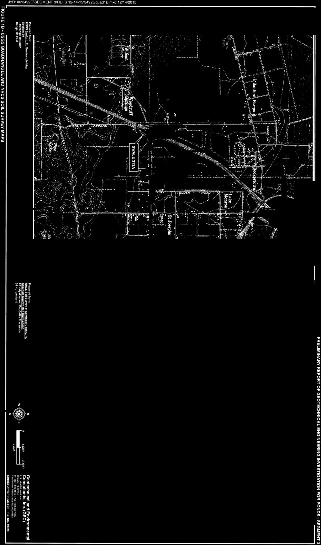
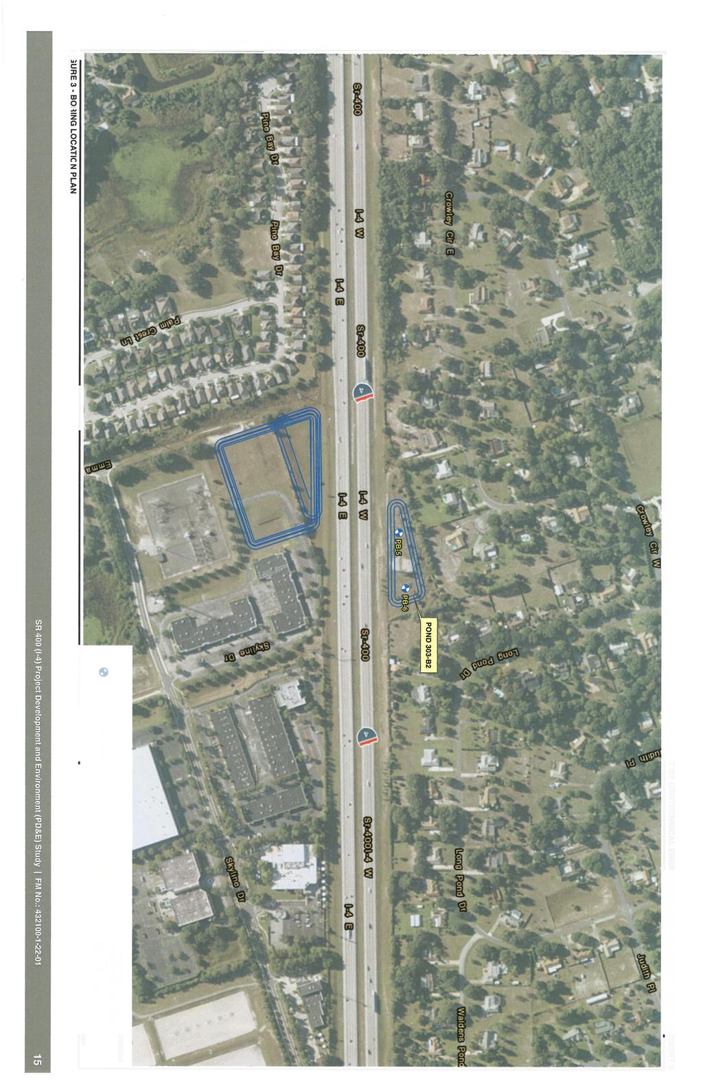
3 TABLE OF CONTENTS 1.0 Project Description and Purpose Review of Available Information USGS Quadrangle Map NRCS Soil Survey Review Geology/Hydrology Potentiometric Surface Subsurface Exploration Machine Auger Borings Field Permeability Tests Groundwater Measurement Laboratory Testing Description of Subsurface Conditions Pond Auger Boring Results Groundwater Levels Preliminary Geotechnical Recommendations Stormwater Ponds Use of This Report APPENDIX Figures 1A and 1B: Figures 2-4: Figure 5: Figure 6: Table 5 : Table 6 : USGS Quadrangle and NRCS Soil Survey Maps Boring Location Plans Pond Soil Survey Sheet Pond Auger Boring Results Summary of Laboratory Test Results Summary of Groundwater Tables and Permeability Tests SR 400 (I-4) Project Development and Environment (PD&E) Study FM No.:
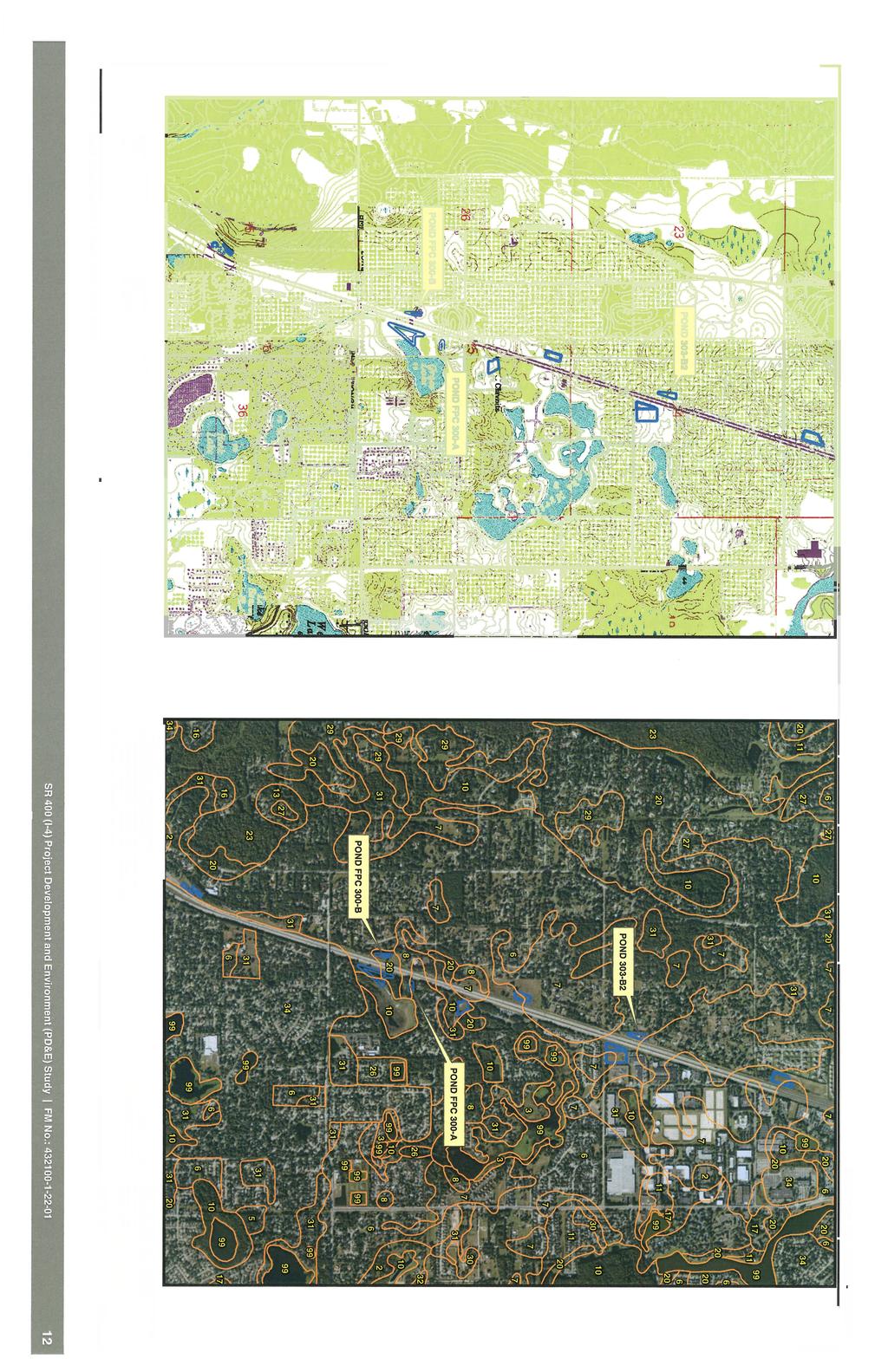
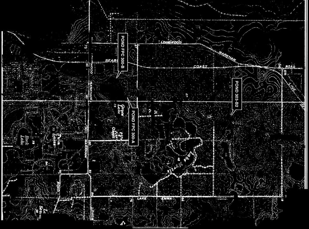
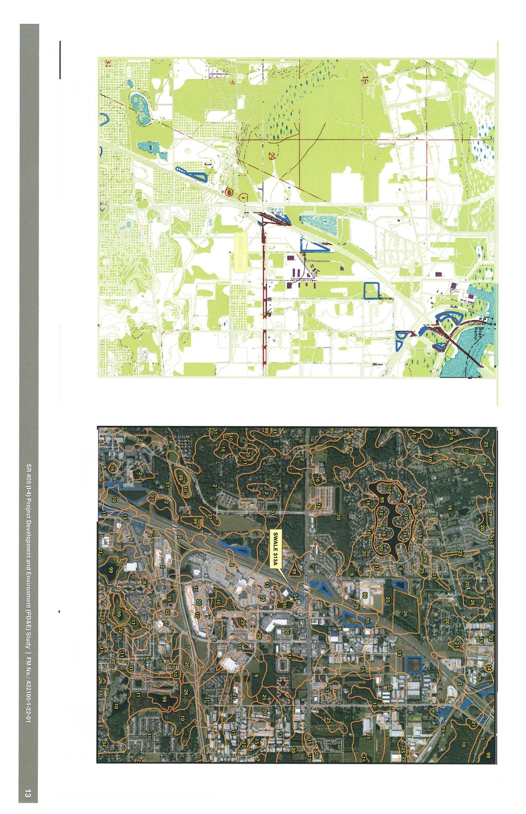
4 1.0 Project Description and Purpose The Florida Department of Transportation (FDOT) is proposing to reconstruct and widen I-4 as part of the I-4 Ultimate concept. This involves the build-out of I-4 to its ultimate condition through Central Florida, including segments in Polk, Osceola, Orange, Seminole, and Volusia Counties. The concept design proposed the addition of two (2) new express lanes in each direction giving it a total of ten (10) dedicated lanes. This Report of Preliminary Geotechnical Investigation has been prepared as a part of the SR 400 (I-4) Project Development and Environment (PD&E) Study. The PD&E Study is being performed for the proposed improvements to an approximately 40 mile long stretch of SR 400 (I-4) from US 27 to Kirkman Road and from east of SR 434 to SR 472. This PD&E project is divided into five separate segments (Segment 1, 2, 3, 4 and 5). Segment 3 of the project is located in southwest Seminole County, Florida. The approximate Segment 3 project limits begin east of SR 434 and extend to east of US 17/92. The typical section for this segment includes a 6-lane divided grassed median interstate with grassed right-of-way and stormwater ponds/roadside swales within the right-of-way. This Report of Preliminary Geotechnical Investigation includes geotechnical investigation and analyses at the three requested alternative stormwater pond locations and one swale location within Segment 3. The Segment 3 project alignment is bordered by mostly residential construction along with spare commercial buildings. However, there are small sections of undeveloped land consisting of pine flatwoods and palmetto bushes. Two of the proposed ponds are located in heavily wooded area and the third is located on the same site as an existing billboard. The project study area is shown on a United States Geological Society (USGS) Quadrangle Map and the United States Department of Agriculture (USDA) National Resource Conservation Services (NRCS) Soil Survey Map provided on Figures 1A and 1B. 2.0 Review of Available Information GEC reviewed available data including the USGS Quadrangle map and USDA NRCS Soil Survey map to obtain information on soil and groundwater conditions along the proposed alignment. The results of our review are presented in the following report sections. 2.1 USGS Quadrangle Map The pond locations for Segment 3 are depicted on the USGS Forest City, Casselberry and Sanford, Florida Quadrangle maps shown on Figures 1A and 1B. Review of the USGS Quadrangle maps indicates that the natural ground surface elevation for the 3-investigated ponds in Segment 3 ranges from approximately +60 feet NGVD to +75 feet NGVD and for the new swale near SR 46 is approximately +30 feet NGVD. 2.2 NRCS Soil Survey Review The Natural Resources Conservation Service (NRCS) (formerly SCS) Soil Survey of Seminole County, Florida was reviewed for near-surface soil and groundwater information at the site. The NRCS Soil Survey map of the site vicinity is shown on Figures 1A and 1B in the Appendix. The NRCS soil units at the project site are summarized in Table 1 below: SR 400 (I-4) Project Development and Environment (PD&E) Study FM No.:
5 Table 1 Seminole County NRCS Soil Survey Review Soil Name Depth (in) Soil Description AASHTO Soil Classification Seasonal High Groundwater Depth (ft) Astatula fine sand, Fine sand to 5 percent slopes 4-80 Fine sand, sand Fine sand > 6 A Apopka fine sand, 0 to Sandy clay loam, sandy loam, A-6, A-2-4, 5 percent slopes sandy clay A-2-6, A-4 Astatula fine sand 5 to 0-3 Fine sand 8 percent slopes 3-80 Fine sand, sand A Fine sand > 6 Apopka fine sand, 5 to Sandy clay loam, sandy loam, A-2-6, A-4, 8 percent slopes sandy clay A-6, A-2-4 Astatula fine sand, Fine sand to 12 percent slopes 3-80 Fine sand, sand Fine sand > 6 A Apopka fine sand, 8 to Sandy clay loam, sandy loam, A-2-6, A-4, 12 percent slopes sandy clay A-6, A Fine sand, sand Myakka fine sand Fine sand, sand, loamy fine A-2-4, sand Fine sand, sand Fine sand Fine sand, sand A-2-4, A/D EauGallie fine sand Sandy clay loam, sandy loam, A-2-6, A-2-4 fine sandy loam Loamy sand, sand, loamy fine A-2-4, sand 34 Urban Land Map Symbol Hydrologic Group Based on review of the NRCS soil survey map, the soils within the area of the proposed ponds in Segment 3 are characterized as sands with variable silt content (, A-2-4). For the majority of the soils within the 3 pond footprints the soil survey lists seasonal high water table levels at depths greater than 6 feet below the existing ground surface. However, the estimated seasonal high groundwater levels do not account for changes in groundwater due to development and are only relevant for the soil s natural, undisturbed condition. The soils in the vicinity of the new swale are generally classified as urban land with no estimated groundwater levels. However, the surrounding natural soils typically have shallow seasonal high groundwater levels within about 1 foot of the natural ground. The NRCS Soil survey map also depicts Urban Land (Soil Unit No. 34) within the project area. Urban Land refers to areas where most of the ground surface is covered by asphalt, concrete, buildings and other impervious surfaces that modify surface/subsurface drainage and obscure or alter the soils so that their identification is not possible. SR 400 (I-4) Project Development and Environment (PD&E) Study FM No.:
6 Information contained in the NRCS Soil Survey should be considered general and may be outdated. Therefore, it may not be reflective of actual soil and groundwater conditions, particularly if recent development in the site vicinity has modified soil conditions or surface/subsurface drainage. The information obtained from the soil borings presented in this report should be considered a more current and accurate characterization of actual site conditions. 2.3 Geology/Hydrology Central Florida geologic conditions can generally be described in terms of three basic sedimentary layers. The upper layer is primarily comprised of sands containing varying amounts of silt and clay. These sands are underlain by a layer of clay, clayey sand, phosphate and limestone which is locally referred to as the Hawthorn formation. The third layer underlies the Hawthorn formation and is comprised of limestone. The thickness of these three strata varies throughout Central Florida. In general, the surficial sands typically extend to depths of 40 to 70 feet, while the Hawthorn formation ranges from nearly absent in some locations to thicknesses greater than 100 feet. The groundwater hydrogeology of Central Florida can be described in terms of the nature and relationship of the three basic geologic strata. The near-surface sand stratum is fairly permeable and comprises the water table (unconfined) aquifer. The limestone formation, known as the Floridan aquifer, is highly permeable due to the presence of large interconnected channels and cavities throughout the rock. The Floridan aquifer is the primary source of drinking water in Central Florida. These two permeable strata are separated by the relatively low permeability clays of the Hawthorn formation. The amount of groundwater flow between the two aquifer systems is dependent on the thickness and consistency of the Hawthorn clay confining beds which, as previously stated, varies widely throughout Central Florida. The geology and hydrogeology described above can be conducive to collapses of the ground surface resulting in circular depressions known as "sinkholes." Sinkholes usually occur due to the downward movement of the near surface sands through openings in the Hawthorn formation into the limestone cavities. This process can be likened to the movement of sand through an hourglass. Sinkholes are most likely to occur in areas where the Hawthorn formation is thin or absent, allowing free downward movement of sands into the limestone. Groundwater also flows freely from the surficial aquifer into the Floridan aquifer in areas where the Hawthorn formation is thin or breached. This phenomenon is called recharge. Therefore, high recharge areas are typically prone to sinkhole activity. An evaluation of sinkhole risk would include performing deep borings to evaluate the nature and thickness of the surficial sands and Hawthorn formation. No method of geological, geotechnical, or geophysical exploration is known that can accurately predict the occurrence of sinkholes. It is common geotechnical practice in Central Florida to make a qualitative prediction of sinkhole risk on the basis of local geological conditions in the vicinity of a particular site. Based on the U.S. Geological Survey Map entitled Recharge and Discharge Areas of the Floridan Aquifer in the St. Johns River Water Management District and Vicinity, Florida, 1984, the project lies in a known high recharge area, and SR 400 (I-4) Project Development and Environment (PD&E) Study FM No.:
7 therefore, we can conclude based solely on this data that it also lies in an area where the relative risk of sinkhole formation is high compared to the overall risk across Central Florida. 2.4 Potentiometric Surface The potentiometric level of the Floridan Aquifer in the vicinity of the project alignment ranges from about +35 to +38 feet NGVD at the south end of the project site and from +32 to +35 at the north end of the project. Ground surface elevations at the south end of the project vary approximately between +60 and +75 feet NGVD and between +31 and +35 feet NGVD at the north end; therefore, excavations (especially at the north end of the project) may be impacted by artesian flow conditions if underlying confining layer(s) are penetrated during construction. 3.0 Subsurface Exploration In addition to consulting the sources of information previously discussed for regional and site-specific soils data, GEC conducted a subsurface exploration to evaluate soil and groundwater conditions at the pond and swale locations provided to us by HNTB. The subsurface exploration for this study generally consisted of performing 2 machine auger borings to a depth of 20 feet below the existing ground surface, along with one field permeability test at each of the proposed pond locations as well as borings and field permeability tests at the swale location requested by HNTB. The borings were not surveyed in the field but were established in the field using project plans and a handheld, sub-meter accuracy, Global Positioning Satellite (GPS) unit (Trimble Geo7X) and should be considered approximate. Although these boring locations are, therefore, given only approximately, the methods used to locate them are, in GEC s opinion, sufficient to meet the intent of this study. The boring locations are indicated on the Boring Location Plan sheets, Figures 2 through 4 in the Appendix. 3.1 Machine Auger Borings Machine auger borings were performed in general accordance with ASTM Procedure D Machine auger borings were performed by hydraulically turning continuous flight, solid-stem, auger into the ground in 5-foot increments until the desired boring termination depth was achieved. The auger flights were retrieved in 5-foot increments, without further rotation of the auger, and the retrieved soil was examined by our technician prior to collection of representative samples. A field auger boring log was prepared that detailed the soils penetrated, records the groundwater depth at the time of drilling, if encountered, and includes other details of the boring, methods used, and selected other boring and/or site conditions at the time of drilling. The samples were placed in sealed jars and transported to GEC s laboratory for further examination and limited laboratory testing as needed. 3.2 Field Permeability Tests Constant or falling head permeability tests were performed in the field at this site. The field permeability tests were performed by driving a 3-inch diameter casing into the ground to the desired test depth and washing the soil out of the casing with water. The casing was backfilled with quartz gravel to 24 inches above the bottom of the casing and was then raised a distance of 18 inches. SR 400 (I-4) Project Development and Environment (PD&E) Study FM No.:
8 When a constant head permeability test was conducted, water was added to the casing to achieve a stable water level. Once the water level stabilized, the flow required to maintain the stable water level over time was measured. When a falling head permeability test was conducted, water was added to the casing to achieve a stable water level. Once the water level stabilized, the water source was taken away and the drop in water level in the casing with respect to time was recorded. These relationships were used to calculate the permeability of the soil. Field permeability tests and calculations were performed in general conformance with NAVFAC DM Groundwater Measurement A GEC engineering technician measured the depth to the groundwater in the boreholes at the time of drilling and again after approximately 24 hours. Once the groundwater measurements were recorded, the boreholes were backfilled with soil cuttings to prevailing ground surface. 4.0 Laboratory Testing Selected soil samples retrieved from the borings were tested in accordance with Florida Standard Testing Methods (FM). Florida Standard Testing Methods are adaptations of recognized standard methods, e.g., ASTM and AASHTO, which have been modified to accommodate Florida s geological conditions. The laboratory testing program for this project is summarized on the following table: Table 2 Summary of Laboratory Testing Program Type of Test Number of Tests Grain size analysis (FM 1 - T88) 8 Natural Moisture Content (FM 1-T 265) 2 Atterberg limits (FM 1 - T89/90) 2 Laboratory Soil Permeability (FM 1-T215) 2 Organic Content (FM 1-T267) 1 The results of our testing are summarized on the Pond Soil Survey Sheet (Figure 5) and the summary of Laboratory Testing Results (Table 5) in the Appendix. Soil from boring PB-3, sampled from a depth of 7 to 9 feet below the existing ground surface, was submitted to a constant head laboratory soil permeability test. 5.0 Description of Subsurface Conditions The results of our borings are presented on the Pond Auger Boring Results sheet (Figure 6). The soils encountered in the auger borings were classified using the AASHTO Soil Classification System (, A-2-4, etc.). All soils were described using the ASTM soil descriptions (e.g., sand with silt). GEC based the soil classifications on visual examination and the limited laboratory test results shown on Figure 5. SR 400 (I-4) Project Development and Environment (PD&E) Study FM No.:
9 The boring logs indicate subsurface conditions only at the specific boring locations at the time of our field exploration. Subsurface conditions, including groundwater levels, at other locations of the project site may differ from conditions we encountered at the boring locations. Moreover, conditions at the boring locations can change over time. Groundwater levels fluctuate seasonally, and soil conditions can be altered by earthmoving operations. The depths and thicknesses of the subsurface strata indicated on the boring logs were interpolated between samples obtained at different depths in the borings. The actual transition between soil layers may be different than indicated. These stratification lines were used for our analytical purposes and actual earthwork quantities measured during construction should be expected to vary from quantities calculated based on the information in this report. 5.1 Pond Auger Boring Results The soil description and stratum numbers used for the pond auger borings are summarized as follows: Table 3 Soil Stratigraphy Stratum No. Soil Description AASHTO Classification 1 Light brown to brown to light gray to gray fine sand and fine sand with silt 2 Brown to dark brown to dark gray fine sand with silt to silty fine sand, occasional trace organic material A Light brown clayey fine sand A Dark brown mucky fine sand A-8 The auger borings conducted in ponds FPC 300-A, FPC 300-B, and 303-B2 and swale 313A typically encountered sand with varying amounts of silt content (Strata 1 and 2;, A-2-4) to the boring termination depths of 10 to 20 feet below the existing ground surface. However, boring SW-1 encountered a layer of organic sandy clay (A-8) from 1 to 1.5 feet below the existing ground surface. Please refer to the Pond Auger Boring Results sheet (Figure 6) for detailed soil and groundwater information at a specific boring location. 5.2 Groundwater Levels Groundwater levels were measured at least 24 hours after completion of the borings. Encountered groundwater depths at the pond boring locations range from 13.1 to 18.9 feet below the existing ground surface. However, groundwater was not encountered in borings PB-3, PB-4 and PB-5, indicated by GNE shown adjacent to the boring profiles. Encountered groundwater depths at the swale boring locations range from 1.7 to 3.2 feet below the existing ground surface. Groundwater levels can vary seasonally and with changes in subsurface conditions between boring locations. Alterations in surface and/or subsurface drainage brought about by site development can also affect groundwater levels. Therefore, groundwater depths measured at different times or at different locations on the site can be expected to vary from those measured by GEC during this investigation. SR 400 (I-4) Project Development and Environment (PD&E) Study FM No.:
10 For purposes of this report, estimated seasonal high groundwater levels are defined as groundwater levels that are anticipated at the end of the wet season during a normal rainfall year under pre-development site conditions. We define a normal rainfall year as a year in which rainfall quantity and distribution were at or near historical averages. We estimate that seasonal high groundwater depths, in the borings where groundwater was encountered, will range from 10 to approximately 15 feet below the existing ground surface for the pond borings, and from 0.5 to 1.2 feet below the existing ground surface for the swale borings. Our encountered and estimated seasonal high groundwater levels are presented on the Pond Auger Boring Results sheet (Figure 6) and Table 6 in the Appendix. 6.0 Preliminary Geotechnical Recommendations The preliminary analyses and recommendations contained in this report are based in part on the data obtained from a limited number of soil samples and groundwater measurements obtained from widely-spaced borings. The investigation methods used indicate subsurface conditions only at the specific boring locations, only at the time they were performed, and only to the depths penetrated. Borings cannot be relied upon to accurately reflect the variations that usually exist between boring locations and these variations may not become evident until construction. These recommendations are provided to aid in alignment selection and preliminary construction costs. A final geotechnical engineering evaluation will be required after the alignment, ponds and typical section have been selected. 6.1 Stormwater Ponds The pond borings generally encountered fine sands with varying amounts of silt (, A-2-4) to the boring termination depths of 10 to 20 feet below the existing ground surface. The majority of the soils encountered in the pond borings appear suitable for use as roadway embankment in accordance with Index 505 of the FDOT Standard. Sands excavated below the water table will need to be dried to moisture content near optimum to achieve the required degree of compaction. GEC performed one permeability test at each of the proposed pond or swale locations. The following table summarizes the result of our field and laboratory permeability tests. Table 4 Summary of Permeability Tests Results Pond/Swale No. Boring No. Depth (ft) Encountered Water Table (ft) Soil Type (AASHTO) Horizontal Permeability, K (ft/day) Perm Type FPC 300-B PB A Falling Head FPC 300-A PB GNE* 30.5 Constant Head 303-B2 PB GNE* 2.2 Falling Head 313A SW Constant Head 313A SW Falling Head 313A SW Constant Head * GNE: Groundwater not encountered to the boring termination depth. SR 400 (I-4) Project Development and Environment (PD&E) Study FM No.:
11 7.0 Use of This Report GEC has prepared this preliminary report for the exclusive use of HNTB, and FDOT, and for specific application to our client s project. GEC will not be held responsible for any third party s interpretation or use of this report s subsurface data or engineering analysis without our written authorization. The sole purpose of the borings performed by GEC at this site was to obtain indications of subsurface conditions as part of a geotechnical exploration program. GEC has not evaluated the site for the potential presence of contaminated soil or groundwater, nor have we subjected any soil samples to analysis for contaminants. GEC has strived to provide the services described in this report in a manner consistent with that level of care and skill ordinarily exercised by members of our profession currently practicing in Central Florida. No other representation is made or implied in this document. The preliminary conclusions or recommendations of this report should be disregarded if the nature, design, or location of the facilities is changed. If such changes are contemplated, GEC should be retained to review the new plans to assess the applicability of this report in light of proposed changes. SR 400 (I-4) Project Development and Environment (PD&E) Study FM No.:


12


13

14


15


16
17

18
19 Table 5 Summary of Laboratory Test Results SR 400 (I-4) PD&&E Study From US 27 to Kirkman Road and From East of SR 434 to SR 472 FPID No GEC Project No. 3492G Percent Passing by Weight Atterberg Limits Pond/Swale Number Stratum Number Boring Number Sample Depth (feet) #10 Sieve #40 Sieve #60 Sieve #100 Sieve #200 Sieve Moisture Content (%) Liquid Limit Plasticity Index Organic Content (%) AASHTO Class. FPC 300-A 1 PB B2 1 PB A 1 SW A 1 SW A 1 SW FPC 300-B 2 PB A-2-4 FPC 300-A 2 PB NP NP --- A A 4 SW A-8 SR 400 (I-4) Project Development and Environment (PD&E) Study FM No.:
20 Table 6 Summary of Groundwater Tables and Permeability Results SR 400 (I-4) PD&&E Study From US 27 to Kirkman Road and From East of SR 434 to SR 472 FPID No GEC Project No. 3492G Pond/Swale No. FPC 300-B Boring No. Date of Groundwater Measurement *Encountered Groundwater Depth (feet) Estimated Seasonal High Groundwater Depth (feet) NRCS Soil Survey Unit No. NRCS Soil Survey Seasonal High Groundwater Depth Range (feet) Horizontal Permeability Rate (ft/day) Field Permeability Test Results PB-1 09/03/ A-2-4 PB-2 09/03/ Test Depth (ft) Soil Type FPC 300-A PB-3 08/26/ > PB-4 08/26/ > B2 PB-5 08/26/ > PB-6 08/26/ > SW-1 04/20/ A SW-2 04/20/ SW-3 04/20/ SW-4 04/20/ * GNE: Groundwater not encountered to the boring termination depth. SR 400 (I-4) Project Development and Environment (PD&E) Study FM No.:
Report of Preliminary Geotechnical Engineering Investigation for Ponds
 Report of Preliminary Geotechnical Engineering Investigation for Ponds Segment 2: State Road 400 (SR 400)/Interstate 4 (I-4) from West of SR 528 (Beachline Expressway) to West of SR 435 (Kirkman Road)
August 15, 2006 (Revised) July 3, 2006 Project No A
 July 3, 2006 Project No A") August 15, 2006 (Revised) July 3, 2006 Project No. 01-05-0854-101A Mr. David Reed, P.E. Protean Design Group 100 East Pine Street, Suite 306 Orlando, Florida 32801 Preliminary Soil Survey Report Polk Parkway
August 15, 2006 (Revised) July 3, 2006 Project No. 01-05-0854-101A Mr. David Reed, P.E. Protean Design Group 100 East Pine Street, Suite 306 Orlando, Florida 32801 Preliminary Soil Survey Report Polk Parkway
100% Report of Geotechnical Engineering Investigation CENTRAL FLORIDA COMMUTER RAIL TRANSIT SUNRAIL PHASE 2 SOUTH Poinciana Vehicle Storage & Light
 100% Report of Geotechnical Engineering Investigation CENTRAL FLORIDA COMMUTER RAIL TRANSIT SUNRAIL PHASE 2 SOUTH Poinciana Vehicle Storage & Light Maintenance Facility (VSLMF) Osceola County, Florida
ORLANDO SANFORD INTERNATIONAL AIRPORT OUTPARCEL 1 SANFORD, FLORIDA
 PRELIMINARY GEOTECHNICAL STUDY ORLANDO SANFORD INTERNATIONAL AIRPORT OUTPARCEL 1 SANFORD, FLORIDA November 9, 2015 Prepared For: Ms. Diane H. Crews, A.A.E. Sanford Airport Authority 1200 Red Cleveland
Preliminary Soil Survey Report
 Florida Department of TRANSPORTATION Preliminary Soil Survey Report Malabar Road (SR 514) PD&E Study From East of Babcock Street (SR 507) to US 1 Brevard County, Florida FPID: 430136 1 22 01 ETDM: 13026
ORLANDO SANFORD INTERNATIONAL AIRPORT OUTPARCEL 6 SANFORD, FLORIDA
 PRELIMINARY GEOTECHNICAL STUDY ORLANDO SANFORD INTERNATIONAL AIRPORT OUTPARCEL 6 SANFORD, FLORIDA November 9, 2015 Prepared For: Ms. Diane H. Crews, A.A.E. Sanford Airport Authority 1200 Red Cleveland
CONDUCTED FOR: PREPARED FOR: 18 October 2010 YPC Project No. 10GY133
 GEOTECHNICAL EXPLORATION AND ENGINEERING SERVICES REPORT CONDUCTED FOR: Immokalee Stormwater Master Plan Implementation Immokalee, Collier County, Florida PREPARED FOR: Mr. Marc Stonehouse, P. E. Project
100% Report of Geotechnical Engineering Investigation for Structures CENTRAL FLORIDA COMMUTER RAIL TRANSIT SUNRAIL PHASE 2 SOUTH MP A811.
 100% Report of Geotechnical Engineering Investigation for Structures CENTRAL FLORIDA COMMUTER RAIL TRANSIT SUNRAIL PHASE 2 SOUTH MP A811.3 Shingle Creek Bridge Financial Project No. 423446-9-52-01 GEC
REPORT OF GEOTECHNICAL EXPLORATION WEST MARJORY AVENUE TAMPA, FLORIDA
 REPORT OF GEOTECHNICAL EXPLORATION WEST MARJORY AVENUE TAMPA, FLORIDA AREHNA PROJECT NO. B-15-008 March 11, 2015 Prepared For: City of Tampa Stormwater Division 306 W. Jackson Street, 6N Tampa, Florida
PART 1b. Section 7.2 of SJRWMD Special Publication SJ93-SP10
 PART 1b GEOTECHNICAL INVESTIGATION TO ESTIMATE AQUIFER PARAMETERS Note the word is estimate & not determine. Must appreciate the physical meaning of each aquifer parameter. Aquifer, in this sense, does
PART 2D. Section 7.2 of SJRWMD Special Publication SJ93-SP10
 PART 2D GEOTECHNICAL INVESTIGATION TO ESTIMATE AQUIFER PARAMETERS Note the word is estimate & not determine. Must appreciate the physical meaning of each aquifer parameter. Aquifer, in this sense, does
GEOTECHNICAL INVESTIGATION & ASSESSMENT TO ESTIMATE AQUIFER PARAMETERS
 GEOTECHNICAL INVESTIGATION & ASSESSMENT TO ESTIMATE AQUIFER PARAMETERS SJRWMD PONDS WORKSHOP! Note the word is estimate & not determine! Must appreciate the physical meaning of each aquifer parameter!
Final Report of Geotechnical Engineering Investigation For Miscellaneous Structures WEKIVA PARKWAY (SR 429) SECTION 7A From 0.
 SECTION 7A From 0.") Final Report of Geotechnical Engineering Investigation For Miscellaneous Structures WEKIVA PARKWAY (SR 429) SECTION 7A From 0.2 Miles West of Longwood-Markham Road to 0.1 Miles East of Orange Boulevard
Final Report of Geotechnical Engineering Investigation For Miscellaneous Structures WEKIVA PARKWAY (SR 429) SECTION 7A From 0.2 Miles West of Longwood-Markham Road to 0.1 Miles East of Orange Boulevard
This report presents the findings of the subsurface exploration concerning the design of the taxiway rehabilitation. Description
 September 22, 2016 American Infrastructure Development, Inc. 3810 Northdale Boulevard, Suite 170 Tampa, Florida 33624 Attn: Mr. Mohsen Mohammadi, Ph.D., P.E. Senior Consultant Mob: (813) 244-6609 E-mail:
TABLE OF CONTENTS. 5.0 LABORATORY TESTING Corrosion Series Testing Consolidation Testing... 5
 TABLE OF CONTENTS 1.0 SITE AND PROJECT DESCRIPTION... 1 2.0 NRCS SOIL SURVEY... 1 3.0 USGS POTENTIOMETRIC MAP DATA... 2 4.0 SUBSURFACE EXPLORATION... 3 4.1 SPT Borings... 3 4.2 Groundwater Measurement...
REPORT OF GEOTECHNICAL EXPLORATION AND ENGINEERING ANALYSIS
 FIGURE 3 Geotechnical Report (2) REPORT OF GEOTECHNICAL EXPLORATION AND ENGINEERING ANALYSIS RIVER TOWER RESTORATION RIVER TOWER PARK TAMPA, FLORIDA AREHNA PROJECT NO. B-13-002 February 22, 2013 Prepared
CONDUCTED FOR: PREPARED FOR: 5 May 2016 YPC Project No. 16GY146
 GEOTECHNICAL EXPLORATION SERVICES REPORT CONDUCTED FOR: Collier Boulevard PREPARED FOR: Mr. Christopher L. Johnson Director of Land Development Stock Development, LLC Professional Circle, Suite 01 Naples,
Report of Exploratory Test Pits
 Report of Exploratory Test Pits UNF Transportation Projects Stockpile Investigation Osprey Ridge Road Extension Jacksonville, Florida CSI Geo Project No.: 71-17-135-20 Arcadis Project No.: JK017002.0001
Report of Geotechnical Engineering Investigation OIA SOUTH CELL LOT (W340) AID Project No. GOA16001 Orange County, Florida GEC Project No.
 AID Project No. GOA16001 Orange County, Florida GEC Project No.") Report of Geotechnical Engineering Investigation OIA SOUTH CELL LOT (W40) AID Project No. GOA16001 Orange County, Florida GEC Project No. 956G July 6, 2017 American Infrastructure Development, Inc. 7 North
Report of Geotechnical Engineering Investigation OIA SOUTH CELL LOT (W40) AID Project No. GOA16001 Orange County, Florida GEC Project No. 956G July 6, 2017 American Infrastructure Development, Inc. 7 North
GEOTECHNICAL INVESTIGATION PROPOSED OUTFALL LOCATION CITY OF MORGAN S POINT DRAINAGE HARRIS COUNTY, TEXAS REPORT NO
 GEOTECHNICAL INVESTIGATION PROPOSED OUTFALL LOCATION CITY OF MORGAN S POINT DRAINAGE HARRIS COUNTY, TEXAS REPORT NO. 1140198001 Reported to: SIRRUS ENGINEERS, INC. Houston, Texas Submitted by: GEOTEST
Ardaman & Associates, Inc. Geotechnical, Environmental and Materials Consultants
 SUBSURFACE SOIL EXPLORATION ANALYSIS AND RECOMMENDATIONS PROPOSED WEIRS AT STATIONS 130+00 AND 16+00 DRAINAGE IMPROVEMENTS TO THE FOUR CORNERS MSBU HENDRY COUNTY, FLORIDA Ardaman & Associates, Inc. Geotechnical,
How & Where does infiltration work? Context: Summary of Geologic History Constraints/benefits for different geologic units
 Associated Earth Sciences, Inc. Associated Earth Sciences, Inc. Presented by: Matthew A. Miller, PE April 23, 2013 How & Where does infiltration work? Context: Summary of Geologic History Constraints/benefits
September 9, Corzo Castella Carballo Thompson Salman, P.A. 901 Ponce de Leon Boulevard Suite 900 Coral Gables, Florida 33134
 September 9, 2009 Corzo Castella Carballo Thompson Salman, P.A. 90 Ponce de Leon Boulevard Suite 900 Coral Gables, Florida 3334 Attn: Mr. Ian John, E.I. Re: Exfiltration Test Results Glenroyal East Phase
SUMMARY REPORT OF A GEOTECHNICAL SITE EXPLORATION LACROSSE CITRUS REPOSITORY LACROSSE, ALACHUA COUNTY, FLORIDA. GSE PROJECT No.
 SUMMARY REPORT OF A GEOTECHNICAL SITE EXPLORATION LACROSSE CITRUS REPOSITORY LACROSSE, ALACHUA COUNTY, FLORIDA GSE PROJECT No. 1128 Prepared For: BURE OF CITRUS BUDWOOD REGISTRATION SEPTEMBER 2011 Certificate
For. Report of Geotechnical Exploration. St. Johns Parkway Race Track Road to Espada Lane 8-inch Reclaimed Water Main St.
 Report of Geotechnical Exploration For St. Johns Parkway Race Track Road to Espada Lane 8-inch Reclaimed Water Main St. Johns County, FL MAE Project No. 0106-0005 June 14, 2017 Prepared for: CPH, Inc.
April 7, Webster Street Sub-Surface Stormwater Storage System Bid No Bid Date: 4/13/17 ADDENDUM NO 1
 PUBLIC WORKS DEPARTMENT David A. Jones, P.E., Director April 7, 2017 Webster Street Sub-Surface Stormwater Storage System Bid No. 2017-022 Bid Date: 4/13/17 ADDENDUM NO 1 Please make the following changes
mtec REPORT OF GEOTECHNICAL EXPLORATION FTFA Construct Bin Wall at HERD Eglin AFB, Florida
 mtec REPORT OF GEOTECHNICAL EXPLORATION FTFA 14-3001 - Construct Bin Wall at HERD Eglin AFB, Florida MTEC Project Number 2014-101 November 10, 2014 Revised: January 5, 2015 Prepared For: Peterson Engineering,
Estimating the Seasonal High Water Table: A Mix of Art & Science
 Estimating the Seasonal High Water Table: A Mix of Art & Science PONDS WORKSHOP - SJRWMD Devo Seereeram, Ph.D., P.E. This paper was originally written over 4 years ago & generated a lot of interest. The
For. Report of Geotechnical Exploration. University of North Florida Parking Lot 47 Jacksonville, Florida
 Report of Geotechnical Exploration For University of North Florida Parking Lot 47 Jacksonville, Florida MAE Project No. 0019-0009 April 5, 2017 Revised: April 6, 2017 Prepared for: Prepared by: Jacksonville,
Subsurface Environmental Investigation
 Subsurface Environmental Investigation Lake Development East Lake and 21 st Avenue South February 23, 201 Terracon Project No. MP14738A Prepared for: Minneapolis Public Schools Prepared by: Terracon Consultants,
Geotechnical Engineering Report
 BIG CYPRESS SEMINOLE INDIAN RESERVATION WATER TREATMENT FACILITY October 29, 2015 Terracon Project No. HD155065 Prepared for: REISS ENGINEERING, INC. 1016 Spring Villas Pt. Winter Springs, FL 32708 Prepared
October 11, 2011 Re-Issued November 15, 2011
 Shadow Wood Investors LLC 425 W New England Avenue, Suite 425 Winter Park, FL 32789 October 11, 2011 Re-Issued November 15, 2011 LOCATIONS: Atlanta Daytona Beach Fort Myers Fort Pierce Gainesville Jacksonville
Geotechnical Exploration and Evaluation Report
 Geotechnical Exploration and Evaluation Report Pavement Coring and Evaluation UNF Parking Lot 3 Jacksonville, Florida CSI Geo Project No.: 71-18-135-23 Prepared by CSI Geo, Inc. 2394 St. Johns Bluff Road
HSA ENGINEERS & SCIENTISTS. A member of the CRA family of companies
 HSA ENGINEERS & SCIENTISTS A member of the CRA family of companies Report of Pavement Coring and Services Town of Belleair Rosery Road Seawall, Roadway and Drainage Improvements Atkins 4030 West Boy Scout
GEOTECHNICAL INVESTIGATION ADDENDUM Pavement Improvements for Imperial Avenue, Wake Avenue, and Danenberg Drive, El Centro, California
 Mr. Victor Garcia The Holt Group 1601 N. Imperial Ave. El Centro, California 92243 September 28, 2017 Project No. EC595 SUBJECT: REFERENCE: GEOTECHNICAL INVESTIGATION ADDENDUM Pavement Improvements for
REPORT OF GEOTECHNICAL CONSULTING SERVICES
 REPORT OF GEOTECHNICAL CONSULTING SERVICES Escambia County Public Works Department Thompson, Crary and McNeal Roadway Project Escambia County, Century,FL Thompson Engineering Project No.: 15-1101-0297
DEPARTMENT OF TRANSPORTATION DIVISION: MATERIALS REPORT COVER SHEET. Revised Soil Survey Report November 24, 2015 Matthew G. Moore, P.E.
 LD-0 /12/09 DEPARTMENT OF TRANSPORTATION DIVISION: MATERIALS REPORT COVER SHEET Revised Soil Survey Report November 2, 201 Matthew G. Moore, P.E. VDOT (Division) or Company Name Insert Location, Virginia
DRAFT Geotechnical Technical Memorandum
 DRAFT Geotechnical Technical Memorandum US 19 (SR 55) Reevaluation from 66 th Avenue North to SR 690/118 th Avenue North Work Program Item Segment No. 435914-1 Project Development and Environment Study
May 2, Mr. Tim Kurmaskie, AIA ARCHITECT KURMASKIE ASSOCIATES, INC Washington Street Raleigh, NC
 Mr. Tim Kurmaskie, AIA ARCHITECT KURMASKIE ASSOCIATES, INC. 1030 Washington Street Raleigh, NC 27605-1258 May 2, 2017 Re: Report of Subsurface Investigation Westfield Rehabilitation & Health Care Additions
Please include this addendum in your Bid proposal for the above referenced project. Questions are in black ink, and the answers are in red ink.
 JAHarchitects, LLC PROJECT NO. 393 RIVERCREST CDD 11560 RAMBLE CREEK DRIVE, RIVERVIEW FL ADDENDUM TO BID PROJECT: RIVERCREST CDD MULTI PURPOSE FIELD MAINTENANCE BUILDING & DOG PARK POOL & CABANNA JAH PROJECT
Geotechnical Exploration and Evaluation Report
 Geotechnical Exploration and Evaluation Report Nassau Reclaimed Water Main From Radio Avenue to Harts Road Nassau County, Florida CSI Geo Project No.: 71-17-329-04 Client Project No.: JEA 09302-049-01
Sepetember 27, Florida Department of Environmental Protection Attn: Dawn Templin 160 Governmental Center Pensacola, FL
 Bay County Solid Waste 11411 Landfill Rd. Panama City Beach, Florida 32413 Telephone: (850) 236-2212 Fax: (850) 233-5053 Board of County Commissioners www.baycountyfl.gov Sepetember 27, 2018 Florida Department
PROPOSED CONDOS 1129 Victoria Drive, Dunedin Parcel: , Pinellas County Geotechnical Services June Report No.
 Central Florida Testing Laboratories, Inc. Testing, Development and Research 12625-40th Street North Clearwater, Florida 33762 ENGINEERING BUSINESS NO. 1066 GEOLOGY BUSINESS NO. 224 TAMPA BAY AREA (727)
 Appendix A - Vicinity Map Vicinity Map: Palm Beach Gardens City Hall Additions, 000 N Military Trail, Palm Beach Gardens, FL Proposed Location of Police Dept. Attached Addition Proposed Location of New
REPORT OF GEOTECHNICAL EXPLORATION PEPSI PLACE WATER MAIN REPLACEMENT JACKSONVILLE, FLORIDA E&A PROJECT NO CLIENT ID: 4784
 REPORT OF GEOTECHNICAL EXPLORATION PEPSI PLACE WATER MAIN REPLACEMENT JACKSONVILLE, FLORIDA E&A PROJECT NO. 35-55 CLIENT ID: 78 Prepared for: Construction & Engineering Services Consultants, Inc. 93 Baymeadows
For. Report of Geotechnical Exploration. University of North Florida Parking Lot 11 Jacksonville, Florida
 Report of Geotechnical Exploration For University of North Florida Parking Lot 11 Jacksonville, Florida MAE Project No. 0019-0008 January 13, 2017 Prepared for: GAI Consultants 1301 Riverplace Boulevard,
REPORT OF GEOTECHNICAL EXPLORATION GLYNN COUNTY DETENTION CENTER GLYNN COUNTY, GEORGIA E&A PROJECT NO
 REPORT OF GEOTECHNICAL EXPLORATION GLYNN COUNTY DETENTION CENTER GLYNN COUNTY, GEORGIA E&A PROJECT NO. - Prepared for: IPG Architects, Inc. Northwood Park Drive Valdosta, Georgia Prepared by: Ellis & Associates,
PRELIMINARY GEOTECHNICAL INVESTIGATION UCCS ACADEMIC OFFICE BUILDING COLORADO SPRINGS, COLORADO
 PRELIMINARY GEOTECHNICAL INVESTIGATION UCCS COLORADO SPRINGS COLORADO Prepared for: UNIVERSITY OF COLORADO AT COLORADO SPRINGS Facilities Services 1420 Austin Bluffs Parkway Colorado Springs Colorado 80918
ENGINEERING SERVICES REPORT FOREST LAKES BOULEVARD PAVEMENT EVALUATION TAMPA ROAD TO COUNTY LINE FOR PINELLAS COUNTY, FL. May 21, 2010 URS CORPORATION
 ENGINEERING SERVICES REPORT FOREST LAKES BOULEVARD PAVEMENT EVALUATION TAMPA ROAD TO COUNTY LINE FOR PINELLAS COUNTY, FL May 21, 2010 URS CORPORATION May 21, 2010 Mr. Brent D. Hall Senior Department Administrative
Civil Geotechnical Surveying
 Civil Geotechnical Surveying Mr. David Burnett Cabarrus County Schools 4425 Old Airport Road Charlotte, North Carolina 28025 May 16, 2017 Reference: Geotechnical Engineering Evaluation Future PLC Site
Air Quality Analysis Technical Memorandum
 Air Quality Analysis Technical Memorandum Segment 2: State Road 400 (SR 400) / Interstate 4 (I-4) from West of SR 528 (Beachline Expressway) to West of SR 435 (Kirkman Road) Orange County (75280), Florida
Ardaman & Associates, Inc. Geotechnical, Environmental and Materials Consultants
 SUBSURFACE SOIL EXPLORATION ANALYSIS AND RECOMMENDATIONS CREEKSIDE BOULEVARD FORCE MAIN EXTENSION AND INTERCONNECT NAPLES, COLLIER COUNTY, FLORIDA COLLIER COUNTY PROJECT NO. 700.2. P.O. #0003, CN #3-66
APPENDIX A DRAINAGE STUDY PHASE 2 ALTERNATIVE IMPROVEMENTS CRYSTAL LAKE ALTERNATIVE 4C IMPROVEMENTS LAKEWOOD PIRATELAND SWASH HORRY COUNTY, SC
 DRAINAGE STUDY PHASE ALTERNATIVE IMPROVEMENTS CRYSTAL LAKE ALTERNATIVE C IMPROVEMENTS ` FOR: LAKEWOOD PIRATELAND SWASH HORRY COUNTY, SC APPENDIX A J-.000 Prepared by: Savannah, GA Charleston, SC Myrtle
PAVEMENT DESIGN SUMMARY TANGERINE ROAD CORRIDOR PROJECT INTERSTATE 10 TO LA CANADA DRIVE PIMA COUNTY, ARIZONA
 PAVEMENT DESIGN SUMMARY TANGERINE ROAD CORRIDOR PROJECT INTETATE 10 TO LA CANADA DRIVE PIMA COUNTY, ARIZONA Terracon Project No. 3105079, Revision 3 1.0 INTRODUCTION This report presents the results of
HYDROLOGIC FACTORS AFFECTING SINKHOLE DEVELOPMENT IN A WELL FIELD IN THE KARST DOUGHERTY PLAIN, SOUTHWEST OF ALBANY, GEORGIA
 HYDROLOGIC FACTORS AFFECTING SINKHOLE DEVELOPMENT IN A WELL FIELD IN THE KARST DOUGHERTY PLAIN, SOUTHWEST OF ALBANY, GEORGIA Debbie Warner Gordon AUTHOR: Hydrologist, U.S. Geological Survey, Georgia Water
PROJECT NO A. ISSUED: February 29, 2016
 INTERPRETIVE REPORT FOR INFILTRATION SYSTEM DESIGN, PROPOSED VILLA VERONA APARTMENT COMMUNITY, ASSESSOR S PARCEL NUMBERS 311-040-015, 311-040-021, 311-040-024, 311-040-026 AND 311-040-013, LOCATED ON THE
GEOTECHNICAL ENGINEERING REPORT
 GEOTECHNICAL ENGINEERING REPORT PROJECT MINECRAFT ACCESS ROAD BOYDTON PLANK ROAD DINWIDDIE COUNTY, VIRGINIA JOB NUMBER: 37775.003 PREPARED FOR: DINWIDDIE COUNTY PO BOX 70 DINWIDDIE COUNTY, STATE 23841
This Page Intentionally Left Blank
 GEOTECHNICAL REPORT This Page Intentionally Left Blank July 30, 2014-Revised December 11, 2013 South Florida Water Management District 3301 Gun Club Road West Palm Beach, Florida 33406 Attn: Mr. Jesse
Report of Geotechnical Exploration For. University of North Florida Kernan Shuttle Stop Jacksonville, Florida
 Report of Geotechnical Exploration For University of North Florida Kernan Shuttle Stop Jacksonville, Florida MAE Project No. 0016-0023 March 18, 2015 Prepared for: Prepared by: Jacksonville, Florida 32256
GEOTECHNICAL STUDY PROPOSED CONCRETE ROADWAY TIKI ISLAND COMMUNITY GALVESTON COUNTY, TEXAS PROJECT NO E
 GEOTECHNICAL STUDY PROPOSED CONCRETE ROADWAY TIKI ISLAND COMMUNITY GALVESTON COUNTY, TEXAS PROJECT NO. 15-945E TO VILLAGE OF TIKI ISLAND TIKI ISLAND, TEXAS BY SERVICING TEXAS, LOUISIANA, NEW MEXICO, OKLAHOMA
ADDENDUM NO. 1. PROJECT NAME: Bostic Pelt Road NRCS Drainage Improvements PRI PROJECT NO: Wakulla Co ITB#
 ADDENDUM NO. 1 DATE: January 22, 214 TO: Prospective Bidders via individual e-mails FROM: Alan Wise, P.E. PROJECT NAME: Bostic Pelt Road NRCS Drainage Improvements PRI PROJECT NO: 23.15 ---- Wakulla Co
Report of Geotechnical Exploration For Baymeadows Road/Old Still PUD 6 inch Reclaimed Water Main Jacksonville, FL
 Report of Geotechnical Exploration For Baymeadows Road/Old Still PUD inch Reclaimed Water Main Jacksonville, FL MAE Project No. 0 000 June, 0 Prepared for: CPH, Inc. 00 Belfort Road, Suite 0 Jacksonville,
DEPARTMENT OF TRANSPORTATION DIVISION: MATERIALS REPORT COVER SHEET. Soil Survey Report March 29, 2015 Matthew G. Moore, P.E.
 LD-40 /12/09 DEPARTMENT OF TRANSPORTATION DIVISION: MATERIALS REPORT COVER SHEET Soil Survey Report March 29, 201 Matthew G. Moore, P.E. VDOT (Division) or Company Name Insert Location, Virginia Insert
EXHIBIT G GEOTECHNICAL REPORT (DRAFT)
") EXHIBIT G GEOTECHNICAL REPORT (DRAFT) APPENDIX 1 PROJECT SITE 'B' B-1 B-2 I-2 B-3 B-4 B-5 I-1 PROJECT LOCATION LEGEND B-1 = APPROXIMATE BORING LOCATION I-1 = APPROXIMATE INFILTRATION
EXHIBIT G GEOTECHNICAL REPORT (DRAFT) APPENDIX 1 PROJECT SITE 'B' B-1 B-2 I-2 B-3 B-4 B-5 I-1 PROJECT LOCATION LEGEND B-1 = APPROXIMATE BORING LOCATION I-1 = APPROXIMATE INFILTRATION
Background Information on the. Peace River Basin
 Background Information on the Peace River Basin Resource Conservation & Development Department August 24 Background Physiography The Peace River drainage basin occupies large parts of Polk, Hardee, DeSoto,
For. Report of Geotechnical Exploration. Beaver St Lane Ave to Carnegie St Trans Water Main Project Jacksonville, FL
 Report of Geotechnical Exploration For Beaver St Lane Ave to Carnegie St Trans Water Main Project Jacksonville, FL MAE Project No. 0106-0002.02 March 30, 2017 Prepared for: CPH, Inc. 5200 Belfort Road,
Determination of Design Infiltration Rates for the Sizing of Infiltration based Green Infrastructure Facilities
 Determination of Design Infiltration Rates for the Sizing of Infiltration based Green Infrastructure Facilities 1 Introduction This document, developed by the San Francisco Public Utilities Commission
Geotechnical Investigation for Navajo Gallup Water Supply Project Reach 26.3
 Geotechnical Investigation for Navajo Gallup Water Supply Project Reach 26.3 Geo-Test Geotechnical Engineering Services Report No. 1-718 for Reach 26.3 Tank Site Geo-Test Job No. 1-718, Addendum No. 1
Geotechnical Investigation Report
 MC Squared, Inc Geotechnical Investigation Report S. Edison Avenue Roadway Improvements City Of Tampa Florida Prepared for: Ms. Barbara Graves City of Tampa DPW Stormwater Engineering 306 E. Jackson St.,6N
Appendix 10-A. Optional Recharge Volume Approach
 Appendix 10-A Optional Recharge Volume Approach Table of Contents APPENDIX SECTION HEADINGS 10-A.0 INTRODUCTION 10-A-2 10-A.1 Horsely Method for Determining Recharge Volumes 10-A-2 10-A.1.1 Basis for Determining
PROJECT INFORMATION... 1 SITE AND SUBSURFACE CONDITIONS... 2 EVALUATION AND RECOMMENDATIONS... 4 CONSTRUCTION CONSIDERATIONS... 5
 TABLE OF CONTENTS Page No. PROJECT INFORMATION... 1 Project Authorization... 1 Project Description... 1 Purpose and Scope of Services... 1 SITE AND SUBSURFACE CONDITIONS... 2 Site Location and Description...
June i TABLE OF CONTENTS
 June 2005 - i - 05-526 TABLE OF CONTENTS SECTION PAGE 1.0 INTRODUCTION... 1 1.1 Purpose of the Investigation... 1 1.2 Description of the Project and Scope of Work... 1 1.3 Site Geology... 1 1.4 Site Description
Typical Subsurface Profile. November 28, 2016
 November 28, 2016 RSCCD Facility Planning, District Construction and Support Services 2323 N. Broadway, Suite 112, Santa Ana, CA 92706 Attn: Re: Ms. Allison Coburn Facilities Project Manager P: (714) 480-7530
REPORT OF GEOTECHNICAL EXPLORATION KINLOCK FM REPLACEMENT NEW MANHOLE STRUCTURE JACKSONVILLE, FLORIDA ECS PROJECT NO A CLIENT ID: 0199
 REPORT OF GEOTECHNICAL EXPLORATION KINLOCK FM REPLACEMENT NEW MANHOLE STRUCTURE JACKSONVILLE, FLORIDA ECS PROJECT NO. 3-6187-A CLIENT ID: 0199 Prepared for: JEA 1 West Church Street Jacksonville, Florida
Air Quality Analysis Technical Memorandum
 Air Quality Analysis Technical Memorandum Segment 1: from west of CR 532 (Polk/Osceola County Line) to west of SR 528 Beachline Expressway June, 2014 Stantec 615 Crescent Executive Court Suite 248 Lake
November 13, IP3406. Mr. Uriah Sowell Rooney Engineering 115 Inverness Drive East, Suite 300, Englewood, CO 80112
 November 13, 2015 103IP3406 Mr. Uriah Sowell Rooney Engineering 115 Inverness Drive East, Suite 300, Englewood, CO 80112 Subject: Infiltration Testing Gates Road Valve Site Sunoco Pennsylvania Pipeline
Florida s Leading Engineering Source
 Since 1988 Florida s Leading Engineering Source Environmental Geotechnical Construction Materials Testing Threshold and Special Inspections Plan Review & Code Compliance Mr. Ron Ridenour Hanson Professional
Applied GeoScience, Inc Hammond Dr., Suite 6 Schaumburg, Illinois
 AGI Project No. 13-276 Subsurface Investigation Report For the Proposed New Retail Center 9601 South Pulaski Road Evergreen Park, Illinois Prepared for Mr. Feras Sweis FHS Design + Build LLC 2010 West
Stormwater Standards. Clackamas County Service District No. 1. Infiltration Testing Guide
 Stormwater Standards Clackamas County Service District No. 1 APPENDIX E Infiltration Testing Guide Table of Contents Appendix E - Infiltration Testing Guide... Page E.1 General... 1 E.2 Basic Method -
March 10, 2017 SITE AND PROJECT INFORMATION
 March 10, 2017 Derek Hawkes, PE NASH COUNTY 120 W. Washington Street - Suite 2004 Nashville, NC 27856 Re: Report of Subsurface Investigation Middlesex Corporate Park, Lot 3 Middlesex, North Carolina GeoTechnologies
POND SEALING OR LINING COMPACTED SOIL TREATMENT
 NATURAL RESOURCES CONSERVATION SERVICE CONSERVATION PRACTICE STANDARD POND SEALING OR LINING COMPACTED SOIL TREATMENT CODE 520 (FT. 2 ) DEFINITION A liner for an impoundment constructed using compacted
5.0 SITE CONDITIONS. 5.1 Surface Conditions
 5.0 SITE CONDITIONS 5.1 Surface Conditions The project site is located at approximately along Ashdown Forest Road and Nichols Canyon Road in the Fiddlers Canyon Area of Cedar City, Utah. At the time of
Geotechnical Investigation
 Geotechnical Investigation Prepared for: Precision Approach Engineering, Inc. Corvallis, Oregon January 16, 2017 Professional Geotechnical Services Foundation Engineering, Inc. GEOTECHNICAL INVESTIGATION
For. Report of Geotechnical Exploration. JEA Northside Switchyard 4377 Heckscher Drive Jacksonville, Florida
 Report of Geotechnical Exploration For 4377 Heckscher Drive Jacksonville, Florida MAE Project No. 007-0007 June 30, 2017 Prepared for: Prepared by: Jacksonville, Florida 3226 Phone (904) 19-6990 Fax (904)
WILLMER ENGINEERING INC. Willmer Project No Prepared for. Clark Patterson Lee Suwanee, Georgia. Prepared by
 SOIL SURVEY REPORT (Revised March 6, 2013) New Hospital Connector Road GDOT Project No. CSSTP-0006-00(276), PI No. 0006276 Duluth, Gwinnett County, Georgia WILLMER ENGINEERING INC. Willmer Project No.
1. Introduction Site Information Site Characteristics Hydrogeologic Setting... 2
 Table of Contents 1. Introduction... 1 1.1 Site Information... 1 1.2 Site Characteristics... 1 1.3 Hydrogeologic Setting... 2 2. Closure Plan... 5 2.1 Closure Description... 5 2.2 Closure Timeframe...
Earth Mechanics, Inc. Geotechnical & Earthquake Engineering
 Earth Mechanics, Inc. Geotechnical & Earthquake Engineering TECHNICAL MEMORANDUM DATE: June 3, 2009 EMI PROJECT NO: 01-143 TO: COPY: FROM: SUBJECT: John Chun, P.E. / Port of Long Beach (POLB) Jorge Castillo
GFA INTERNATIONAL FLORIDA S LEADING ENGINEERING SOURCE
 GFA INTERNATIONAL FLORIDA S LEADING ENGINEERING SOURCE Report of Geotechnical Exploration Addie s Corner Entry Bridge and Lake Areas 8799 Immokalee Road Naples, Collier County, Florida October 26, 2016
GEOTECHNICAL SUBSURFACE DATA REPORT
 GEOTECHNICAL SUBSURFACE DATA REPORT SC-41 REPLACEMENT BRIDGE OVER MAIDEN DOWN SWAMP MARION COUNTY, SOUTH CAROLINA PREPARED FOR Mr. Joshua Meetze, E.I.T. RPG-2 GDS South Carolina Department of Transportation
March 28, Port of Kalama Mr. Jacobo Salan 380 West Marine Drive Kalama, Washington 98625
 11917 NE 95 th Street, Vancouver, Washington 98682 Phone: 360-823-2900, Fax: 360-823-2901 March 28, 2014 Port of Kalama Mr. Jacobo Salan 380 West Marine Drive Kalama, Washington 98625 Re: Construction
PROJECT CULVERT REPLACEMENTS GEOTECHNICAL ENGINEERING REPORT CONTRACT No WO01 PALM BEACH COUNTY, FL FEBRUARY 2013
 SOUTH FLORIDA WATER MANAGEMENT DISTRICT PROJECT CULVERT REPLACEMENTS GEOTECHNICAL ENGINEERING REPORT CONTRACT No. 4600002703-WO01 PALM BEACH COUNTY, FL FEBRUARY 2013 Prepared for: South Florida Water Management
Geotechnical Investigation Long Timber Brewing Building Highway 99 and Kelly Street Monroe, Oregon TABLE OF CONTENTS
 Highway 99 and Kelly Street TABLE OF CONTENTS PROJECT INFORMATION... 1 FIELD EXPLORATION... 1 SITE CONDITIONS... 2 Surface Conditions:... 2 Subsurface Conditions:... 2 FILL.... 2 Topsoil.... 2 Clay Alluvium....
MEMORANDUM. TO: STUART OLSON DOMINION CONSTRUCTION LTD. DATE: JANUARY 31, 14 ATTENTION: MR. Dave Bauder, Construction Manager KENNY K. C.KO, P.ENG.
 MEMORANDUM Levelton Consultants Ltd. 150-12791 Clarke Place Richmond, BC V6V 2H9 Canada Tel: 604 278-1411 Fax: 604 278-1042 E-Mail: rhillaby@levelton.com Web Site: www.levelton.com TO: STUART OLSON DOMINION
Subsurface Investigation Report. Proposed New 1-Story Building 6447 Grand Avenue Gurnee, Illinois
 AGI Project No. -11 Subsurface Investigation Report For the Proposed New 1-Story Building 6447 Grand Avenue Gurnee, Illinois Prepared for Mr. Steve Panko Key Development Partners, LLC North State Street,
The following sections provide the approved standard infiltration testing specifications.
 APPENDIX F.2 INFILTRATION TESTING To properly size and locate stormwater management facilities, it is necessary to characterize the soil infiltration conditions at the location of the proposed facility.
Woodhaven Retirement Community Addition Wentworth Street Livonia, Michigan 48154
 Report of Geotechnical Investigation Woodhaven Retirement Community Addition 9 Wentworth Street Livonia, Michigan 81 Latitude.08 N Longitude 8.898 W Prepared for: Fusco, Shaffer & Pappas, Inc. 0 E. Nine
TECHNICAL MEMORANDUM
 TECHNICAL MEMORANDUM SOIL SAMPLING, TESTING AND LOGGING ULOP GEOTECHNICAL EVALUATION STAR BEND SETBACK LEVEE Sutter County, California Prepared by: BLACKBURN CONSULTING 2491 Boatman Avenue West Sacramento,
July 23, Mr. Richard Miller, Vice President Lake Arrowhead Property Owners Association 7065 Arrowroot Trail Gaylord, Michigan 49735
 Mr. Richard Miller, Vice President Lake Arrowhead Property Owners Association 7065 Arrowroot Trail Gaylord, Michigan 49735 Re: Task No. 3 Report of Findings Section 32, Township 30 North, Range 4 West
REPORT OF GEOTECHNICAL EXPLORATION BYFORGE ENGINEERING FOR REFERENCE ONLY
 REPORT OF GEOTECHNICAL EXPLORATION BYFORGE ENGINEERING FOR REFERENCE ONLY HERITAGE BAY MASTER PUMP STATION ISSUED FOR BID REPORT OF GEOTECHNICAL EXPLORATION PROPOSED INLINE WASTEWATER BOOSTER STATION Collier